set clock MITSUBISHI MONTERO 1987 1.G Workshop Manual
[x] Cancel search | Manufacturer: MITSUBISHI, Model Year: 1987, Model line: MONTERO, Model: MITSUBISHI MONTERO 1987 1.GPages: 284, PDF Size: 14.74 MB
Page 216 of 284

8-196 AUDIO SYSTEM - Service Adjustment Procedures
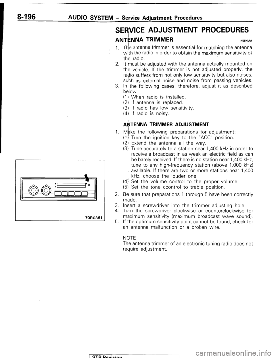
SERVICE ADJUSTMENT PROCEDURES
ANTkNNA TRUMMER NOBNIAA
70R0351
1.
2.
3.
1.
2.
3.
4.
5. The antenna trimmer is essential for matching the antenna
with the radio in order to obtain the maximum sensitivity of
the radio.
It must be adjusted with the antenna actually mounted on
the vehicle. If the trimmer is not adjusted properly, the
radio suffers from not only low sensitivity but also noises,
su’ch as external noise and noise from passing vehicles.
In the following cases, therefore, adjust it as described
below.
(1) When radio is installed.
(2) If antenna is replaced.
(3) If radio has low sensitivity.
(4) If radio is noisy.
AkTENNA TRIMMER ADJUSTMENT
Mgke the following preparations for adjustment:
(1)’ Turn the ignition key to the “ACC” position.
(2) Extend the antenna all the way.
(3) Tune accurately to a station near 1,400 kHz in order to
receive a broadcast in as weak an electric field as can
be barely received. If there is no station near 1,400 kHz,
tune to any high-frequency station (above 1,000 kHz)
available. If there are two or more stations near 1,400
kHz, choose the louder one.
(4) Set the volume control to the proper volume.
(5) Set the tone ccontrol to treble position.
Be sure that preparations 1 through 5 have been correctly
made.
Insert a screwdriver into the trimmer adjusting hole.
Tumrn the screwdriver clockwise or counterclockwise for
maximum sensitivity (maximum broadcast wave sound).
If the optimum sensitivity point cannot be found, check for
an antenna malfunction or a broken wire.
NOTE
The antenna trimmer of an electronic tuning radio does not
require adjustment.
/ STB Revision
Page 271 of 284

AIR-CONDITIONING-Service Adiustment Procedures 24-35
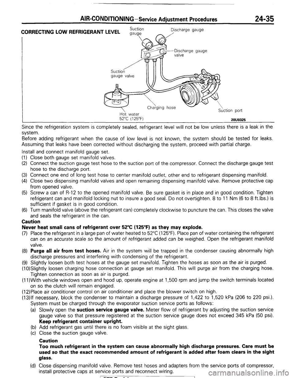
CORRECTING LOW REFRIGERANT LEVEL Suction
Discharge gauge
gauge
I \- a/
gauge valve
II II Discharge gauge
Ho water
52°C i 125°F)
2OUO325
Since the refrigeration system is completely sealed, refrigerant level will not be low unless there is a leak in the
system.
Before adding refrigerant when the cause of low level is not known, the system should be tested for leaks.
Assuming that leaks have been corrected without discharging the system, proceed with partial charge.
Install and connect manifold gauge set.
(I) Close both gauge set manifold valves.
(2) Connect the suction gauge test hose to the suction port of the compressor. Connect the discharge gauge test
hose to the discharge port.
(3) Connect one end of long test hose to center manifold outlet, other end to refrigerant dispensing manifold.
(4) Close two dispensing manifold valves and open remaining dispensing manifold valve. Remove protective cap
from opened valve.
(5) Screw a can of R-12 to the opened manifold valve. Be sure gasket is in place and in good condition. Tighten
refrigerant can and manifold locking nut to insure a good seal. Do not overtighten. 8 to 11 Nm (6 to 8 ft.lbs.) is
sufficient if gasket is in good condition.
(6) Turn manifold valve (above the refrigerant can) completely clockwise to puncture the can. This closes the valve
and seals the refrigerant in the can. Caution
Never heat small cans of refrigerant over 52°C (125’F) as they may explode.
(7) Place the refrigerant in a large pan of water heated to 52°C (125°F). Place pan of water containing the refrigerant
can on an accurate scale so the amount of refrigerant added can be weighed. Open the refrigerant manifold
valve. (8) Purge all air from test hoses.
Air in the system will be trapped in the condenser causing abnormally high
discharge pressures and interfering with condensing of the refrigerant.
(9) Slightly loosen both test hoses at the gauge set manifold. Tighten the hoses as soon as the air is purged.
(10)Slightly loosen charging hose connection at gauge set manifold. This will purge air from the charging hose.
Tighten connection as soon as air is purged.
(1l)With vehicle windows open and hood up, operate engine at 1,500 rpm and jump the switch terminals located
on so the clutch will remain engaged.
(12)Place air conditioner control on air conditioner and place the blower switch on high.
(13)lf necessary, block the condenser to maintain a discharge pressure of 1,422 to 1,520 kPa (206 to 220 psi.).
System must be charged through the evaporator suction service ports as follows:
(a) Slowly open the suction service gauge valve.
Meter flow of refrigerant by adjusting the suction service
gauge valve so that pressure registered at the suction service gauge does not exceed 345 kPa (50 psi). Keep refrigerant container upright.
(b) Add refrigerant gas until there is no foam visible at the sight glass.
(c) Close the suction gauge valve. Caution
Too much refrigerant in the system can cause abnormally high discharge pressures. Care must be
used so that the exact recommended amount of refrigerant is added after foam clears in the sight
glass.
(d) Close dispensing manifold valve. Remove test hoses and adapters from the service ports of compressor,
install protective caps at service ports and reconnect wiring. / STB Revision
Page 273 of 284

AIR-CONDITION1 G-Service Adjustment Procedures 24-37
water 2OUO326
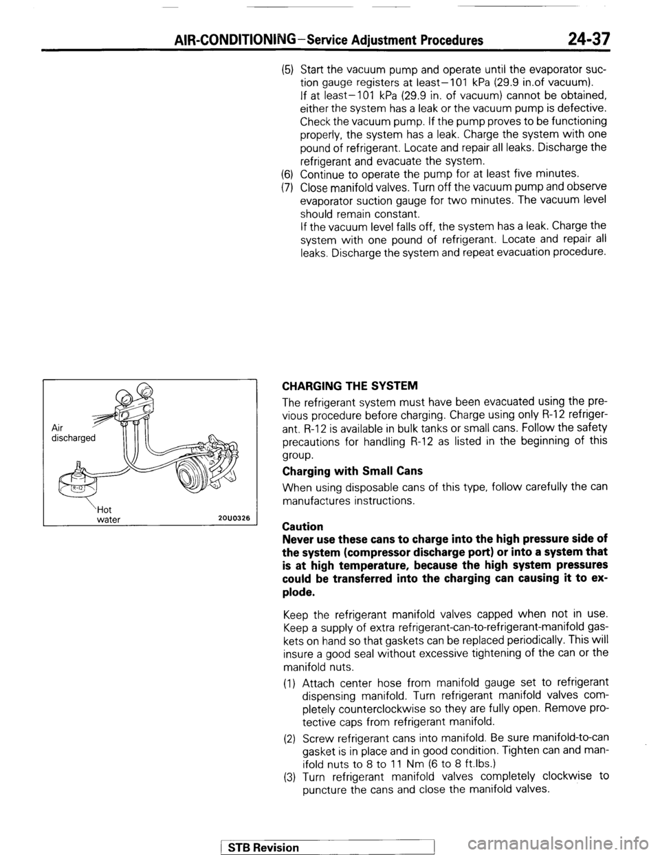
(5) Start the vacuum pump and operate until the evaporator suc-
tion gauge registers at least-101 kPa (29.9 in.of vacuum).
If at least-101 kPa (29.9 in. of vacuum) cannot be obtained,
either the system has a leak or the vacuum pump is defective.
Check the vacuum pump. If the pump proves to be functioning
properly, the system has a leak. Charge the system with one
pound of refrigerant. Locate and repair all leaks. Discharge the
refrigerant and evacuate the system.
(6) Continue to operate the pump for at least five minutes.
(7) Close manifold valves. Turn off the vacuum pump and observe
evaporator suction gauge for two minutes. The vacuum level
should remain constant.
If the vacuum level falls off, the system has a leak. Charge the
system with one pound of refrigerant. Locate and repair all
leaks. Discharge the system and repeat evacuation procedure.
CHARGING THE SYSTEM
The refrigerant system must have been evacuated using the pre-
vious procedure before charging. Charge using only R-l 2 refriger-
ant R-l 2 is available in bulk tanks or small cans. Follow the safety
precautions for handling R-12 as listed in the beginning of this
group.
Charging with Small Cans
When using disposable cans of this type, follow carefully the can
manufactures instructions.
Caution
Never use these cans to charge into the high pressure side of
the system (compressor discharge port) or into a system that
is at high temperature, because the high system pressures
could be transferred into the charging can causing it to ex-
plode.
Keep the refrigerant manifold valves capped when not in use.
Keep a supply of extra refrigerant-can-to-refrigerant-manifold gas-
kets on hand so that gaskets can be replaced periodically. This will
insure a good seal without excessive tightening of the can or the
manifold nuts.
(1) Attach center hose from manifold gauge set to refrigerant
dispensing manifold. Turn refrigerant manifold valves com-
pletely counterclockwise so they are fully open. Remove pro-
tective caps from refrigerant manifold.
(2) Screw refrigerant cans into manifold. Be sure manifold-to-can
gasket is in place and in good condition. Tighten can and man-
ifold nuts to 8 to 11 Nm (6 to 8 ft.lbs.)
(3) Turn refrigerant manifold valves completely clockwise to
puncture the cans and close the manifold valves.
/ ST6 Revision
Page 274 of 284

24-38 AIR-CONDITIONING-Service Adjustment Procedures
(4) Purge the air from the charging line by loosening the charging
hose at the gauge set manifold and turning one of the refrig-
erant valves counterclockwise to release refrigerant. When
the refrigerant gas starts escaping from the loose connection,
re-tighten the hoses.
Caution
Never heat small refrigerant cans over 52°C (125°F) as they
mad explode.
(5) qully open all refrigerant manifold valves being used and place
the cans of refrigerant into a pan containing 52°C (125°F) water
will warm the charging can and aid in the transfer of the charge
into the system. Place the water pan and refrigerant cans on
a scale and note the weight.
(6) Jump the low pressure switch terminals located on the re-
ceiver drier so the clutch will remain engaged.
(7) Start the engine and move the controls to air conditioner
switch on and low blower position.
The low pressure switch will prevent the clutch from engaging
until refrigerant is added to the system. If the clutch does
engage, replace the switch before proceeding any further.
(8) Charge through the suction side of the system by slowly open-
ing the suction manifold valve. Adjust the valve as necessary
so charging pressure does not exceed 345 kPa (50 psi).
Maintain the temperature of the water in the pan by adding
warm water as necessary. Note the weight of water
added, to ensure accuracy when determining amount of
refrigerant added to system.
(9) Adjust the engine speed to a fast idle of approximately 1500
rpm.
(IO) When specified refried refrigerant charge 730 (1.6 Ibs.) has
entered the system, close the gauge set manifold valves,
refrigerant manifold valves, and reconnect wiring. Each
can contains 397 g (14 oz.) of R-12. Use 2 l/2 cans.
1 STB Revision
-1