stop start MITSUBISHI MONTERO 1987 1.G Workshop Manual
[x] Cancel search | Manufacturer: MITSUBISHI, Model Year: 1987, Model line: MONTERO, Model: MITSUBISHI MONTERO 1987 1.GPages: 284, PDF Size: 14.74 MB
Page 118 of 284
8-98 STARTING SYSTEM -Starter Motor
Pinion
6EL003
lEL113
/ Field coil wire
Field coil wire
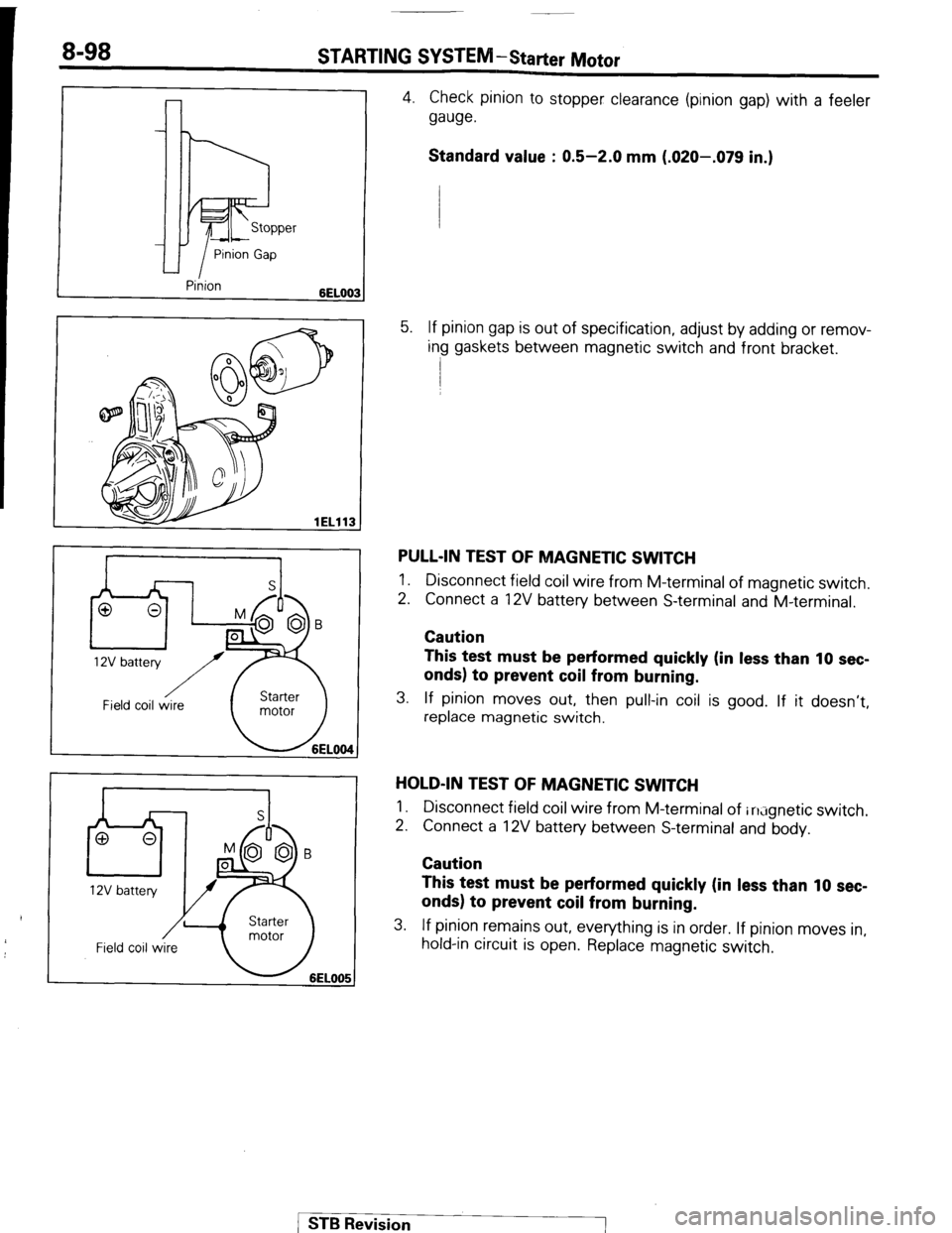
4. Check pinion to stopper clearance (pinion gap) with a feeler
gauge.
Standard value : 0.5-2.0 mm (.020-.079 in.)
5. If pinion gap is out of specification, adjust by adding or remov-
ing gaskets between magnetic switch and front bracket.
PULL-IN TEST OF MAGNETIC SWITCH
1. Disconnect field coil wire from M-terminal of magnetic switch.
2. Connect a 12V battery between S-terminal and M-terminal.
Caution
This test must be performed quickly (in less than 10 sec-
onds) to prevent coil from burning.
3. If pinion moves out, then pull-in coil is good. If it doesn’t,
replace magnetic switch.
HOLD-IN TEST OF MAGNETIC SWITCH
1.
2. Disconnect field coil wire from M-terminal of in;ignetic switch.
Connect a 12V battery between S-terminal and body.
Caution
This test must be performed quickly (in less than 10 sec-
onds) to prevent coil from burning.
3. If pinion remains out, everything is in order. If pinion moves in,
hold-in circuit is open. Replace magnetic switch.
1 ST6 Revision
Page 120 of 284
STARTING SYSTEM -Starter Motor
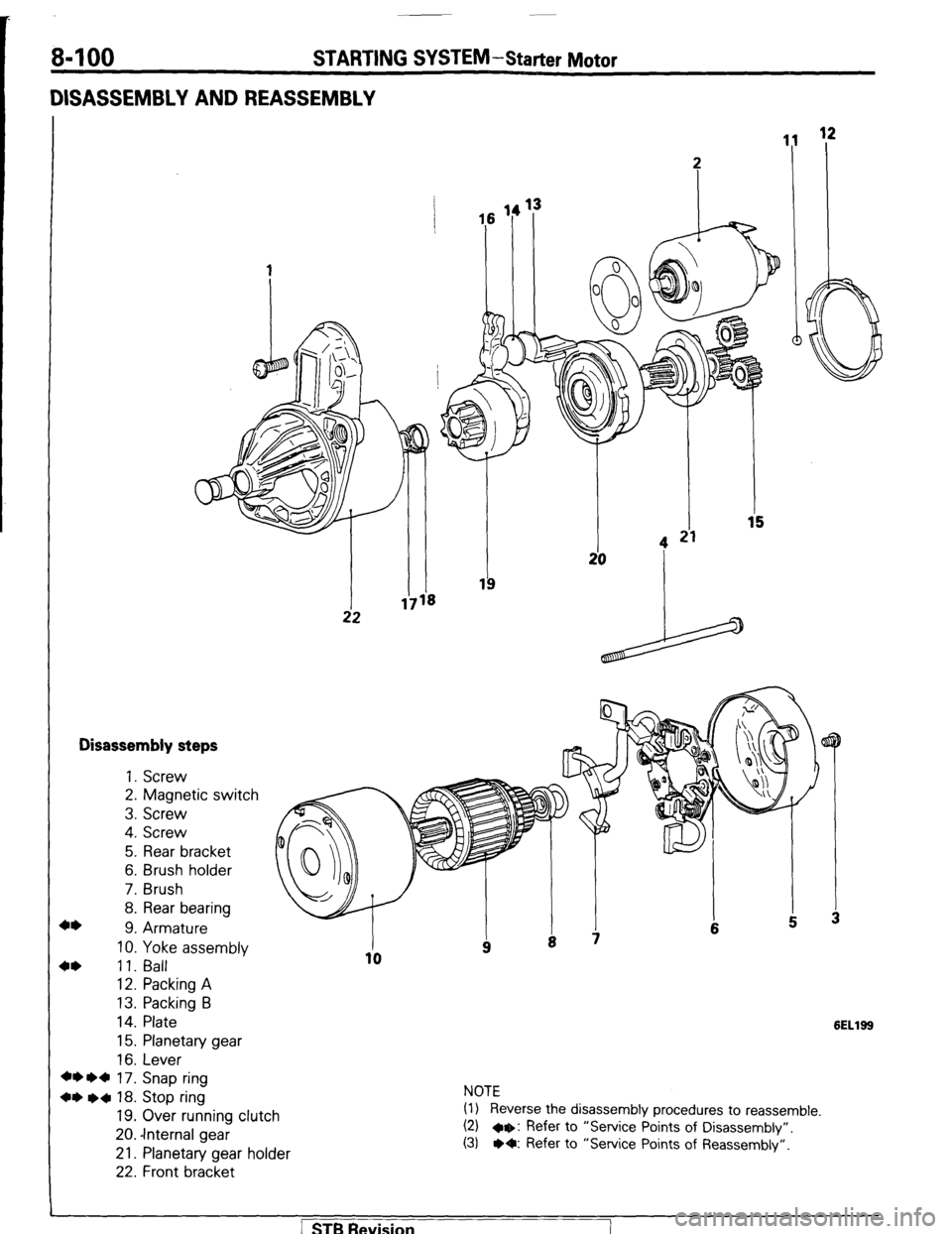
DISASSEMBLY AND REASSEMBLY
Disassembly steps
+* 1. Screw
2. Magnetic switch
3. Screw
4. Screw
5. Rear bracket
6. Brush holder
7. Brush
8. Rear bearing
9. Armature
10. Yoke assembly
4* 11. Ball
12. Packing A
13. Packing B
14. Plate
15. Planetary gear
16. Lever
+* l d 17. Snap ring
+* l a 18. Stop ring
19. Over running clutch
20. -Internal gear
21. Planetary gear holder
22. Front bracket
6ELlSS
NOTE
(1) Reverse the disassembly procedures to reassemble.
(2) a+: Refer to “Service Points of Disassembly”.
(3) l O: Refer to “Service Points of Reassembly”.
] STB Revision
Page 121 of 284
STARTING SYSTEM-Starter Motor 8-101
Snap
L Armature
1ELlO
pi-
SERVICE POINTS OF DISASSEMBLY
9. CAUTION OF ARMATURE/ll. BALL
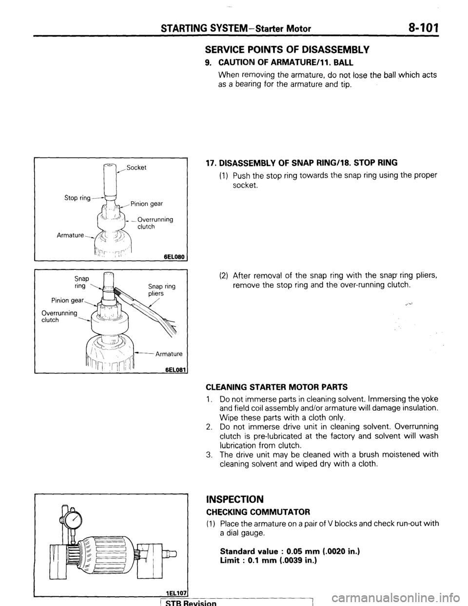
When removing the armature, do not lose the ball which acts
as a bearing for the armature and tip.
17. DISASSEMBLY OF SNAP RING/18. STOP RING
(1) Push the stop ring towards the snap ring using the proper
socket.
(2) After removal of the snap ring with the snap ring pliers,
remove the stop ring and the over-running clutch.
CLEANING STARTER MOTOR PARTS
1, Do not immerse parts in cleaning solvent. Immersing the yoke
and field coil assembly and/or armature will damage insulation.
Wipe these parts with a cloth only.
2. Do not immerse drive unit in cleaning solvent. Overrunning
clutch is pre-lubricated at the factory and solvent will wash
lubrication from clutch.
3. The drive unit may be cleaned with a brush moistened with
cleaning solvent and wiped dry with a cloth.
INSPECTION
CHECKING COMMUTATOR
(1) Place the armature on a pair of V blocks and check run-out with
a dial gauge.
Standard value : 0.05 mm (-0020 in.)
Limit : 0.1 mm (.0039 in.)
wision
I
Page 124 of 284
8-104 STARTING SYSTEM-Starter Motor
SERVICE POINTS OF REASSEMBLY
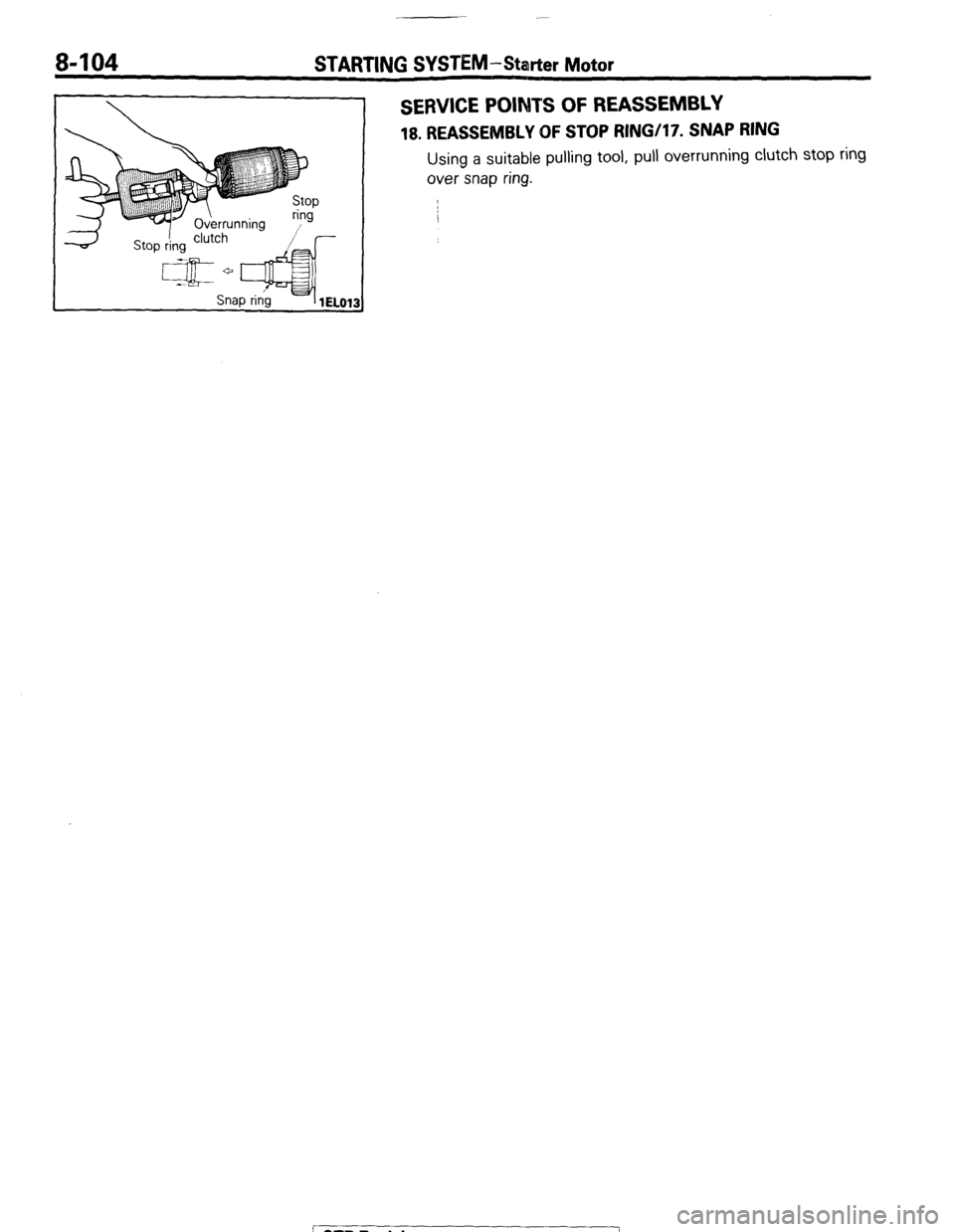
18. REASSEMBLY OF STOP RINGi17. SNAP RING
Using a suitable pulling tool, pull overrunning clutch stop ring
over snap ring.
1 STB Revision
--I
Page 131 of 284
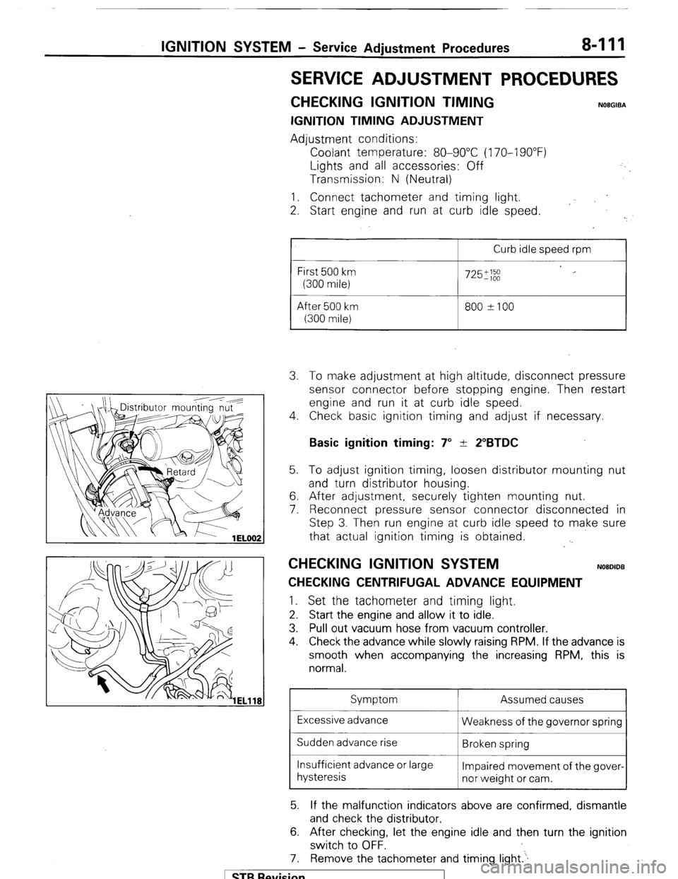
IGNITION SYSTEM - Service Adjustment Procedures 8-111
SERVICE ADJUSTMENT PROCEDURES
CHECKING IGNITION TIMING NOEGIBA
IGNITION TIMING ADJUSTMENT
Adjustment conditions:
Coolant temperature: 80-90°C (170-I 90°F)
Lights and all accessories: Off
Transmission: N (Neutral)
1. Connect tachometer and timing light.
2. Start eng.ine and run at curb idle speed.
I
Curb idle speed rpm
First 500 km
(300 mile)
After 500 km
(300 mile)
725';;;
800 ?I00 3. To make adjustment at high altitude, disconnect pressure
sensor connector before stopping engine. Then restart
engine and run it at curb idle speed.
4. Check basic ignition timing and adjust if necessary.
Basic ignition timing: 7” + 2”BTDC 5. To adjust ignition timing, loosen distributor mounting nut
and turn distributor housing.
6. After adjustment, securely tighten mounting nut.
7. Reconnect pressure sensor connector disconnected in
Step 3. Then run engine at curb idle speed to make sure
that actual ignition timing is obtained.
. .
CHECKING IGNITION SYSTEM NOBDIDB
CHECKING CENTRIFUGAL ADVANCE EQUIPMENT 1.
Set the tachometer and timing light.
2. Start the engine and allow it to idle.
3. Pull out vacuum hose from vacuum controller.
4. Check the advance while slowly raising RPM. If the advance is
smooth when accompanying the increasing RPM, this is
normal.
Symptom Assumed causes
Excessive advance
Weakness of the governor spring
Sudden advance rise
Broken spring
Insufficient advance or large
Impaired movement of the gover-
hysteresis
nor weight or cam.
5. If the malfunction indicators above are confirmed, dismantle
and check the distributor.
6. After checking, let the engine idle and then turn the ignition
switch to OFF.
7. Remove the tachometer and timing light.‘.
1 STB Revision
Page 193 of 284
WIPER AND WASHER SYSTEM - Windshield Wipers 8-173
I Battery
To wiper
motor bracket
16W1540
16W1524
16UO373
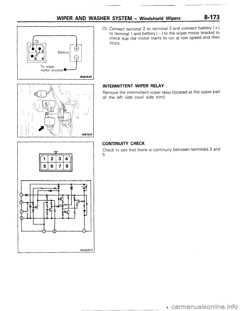
(3) Connect terminal 2 to terminal 3 and connect battery (+)
to terminal 1 and battery (-) to the wiper motor bracket to
check that the motor starts to run at low speed and then
stops.
INTERMITTENT WIPER RELAY
Remove the intermittent wiper relay (located at the upper part
of the left side cowl side trim).
CONTINUITY CHECK
Check to see that there is continuity between terminals 2 and
5.
) STB Revision
Page 196 of 284
8476 WIPER AND WASHER SYSTEM - Rear Wiper
16W1541
Battery
2.3
t
Battery
-
To wiper
motor bracket +
10w1543
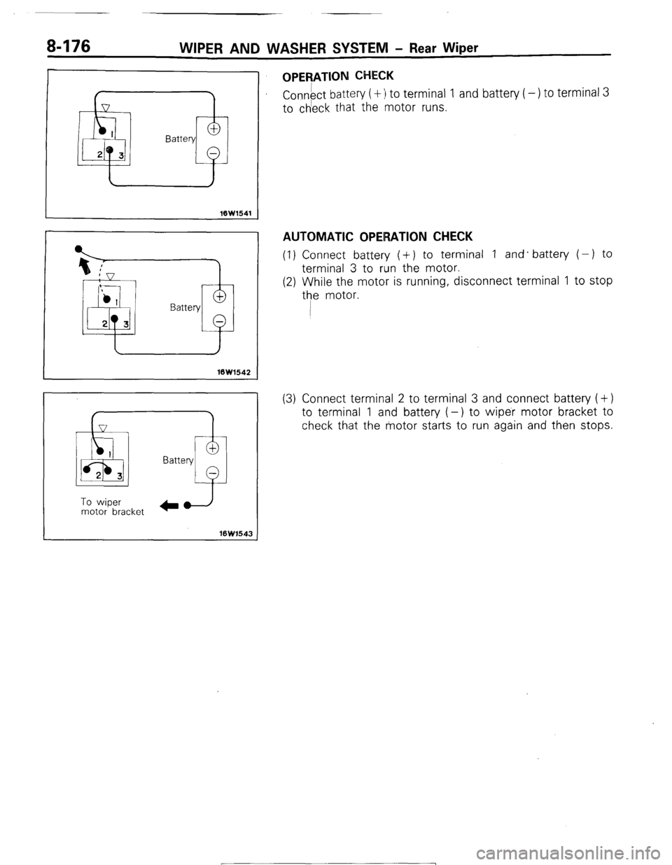
OPERATION CHECK
Connect battery (+ :I to terminal 1 and battery ( -) to terminal 3
to ch’eck that the motor runs.
AUTOMATIC OPERATION CHECK
(1) Connect battery (+) to terminal 1 and. battery ( - ) to
terminal 3 to run the motor.
(2) While the motor is running, disconnect terminal 1 to stop
the motor.
(3) Connect terminal 2 to terminal 3 and connect battery (+)
to terminal 1 and battery (-) to wiper motor bracket to
check that the motor starts to run again and then stops.
1 STB Revision
-7
Page 213 of 284
AUDIO SYSTEM - Specifications 8-193
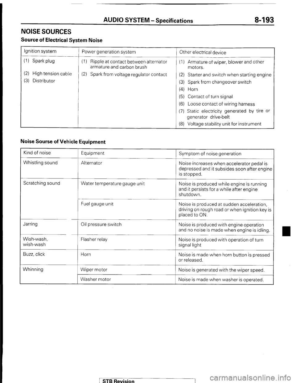
NOISE SOURCES
Source of Electrical System Noise
Ignition system
(1) Spark plug
(2) High tension cable
(3) Distributor Power generation system
(1) Ripple at contact between alternator
armature and carbon brush
(2) Spark from voltage regulator contact
!
Other electrical device
(1) Armature of wiper, blower and other
motors.
(2) Starter and switch when starting engine
(3) Spark from changeover switch
(4) Horn
(5) Contact of turn signal
(6) Loose contact of wiring harness
(7) Static electricity generated by tire or
generator drive-belt
(8) Voltage stability unit for instrument
Noise Sourse of Vehicle Equipment
Kind of noise
Whistling sound Equipment
Alternator Symptom of noise generation
Noise increases when accelerator pedal is
depressed and it subsides soon after engine
is stopped.
Scratching sound
Water temperature gauge unit Noise is produced while engine is running
and it persists for a while after engine
shutdown.
Fuel gauge unit Noise is produced at sudden acceleration,
driving on rough road or when ignition key is
placed to ON.
Jarring
Wish-wash,
wish-wash
Buzz, click Oil pressure switch
Flasher relay
Horn
Wiper motor
Washer motor Noise is produced with engine operation
and no noise is made when engine is idling.
Noise is produced with operation of turn
signal light
Noise is made when horn button is pressed
or released.
Whinning Noise is generated with the wiper speed.
Noise is made when washer is operated.
STB Revision