torque MITSUBISHI MONTERO 1987 1.G Workshop Manual
[x] Cancel search | Manufacturer: MITSUBISHI, Model Year: 1987, Model line: MONTERO, Model: MITSUBISHI MONTERO 1987 1.GPages: 284, PDF Size: 14.74 MB
Page 3 of 284
INTRODUCTION - H
ow To Use This Manual 3
-L
!
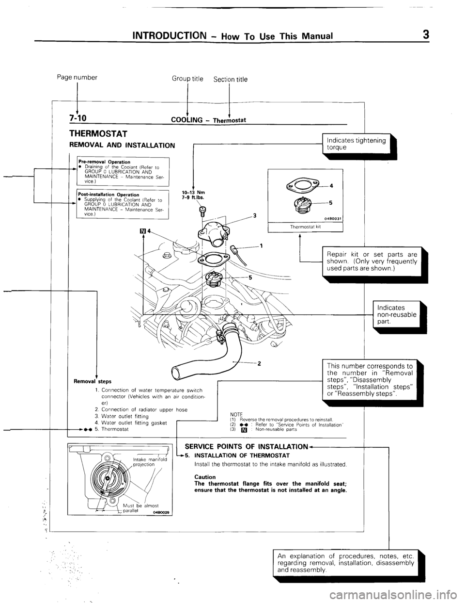
Page number
Group title
Section title
THERMOSTAT
REMOVAL AND INSTALLATION
I
I I
L
1 torque
Removal +
I s 0480031
Thermostat kit
Repair kit or set parts are
1. Connectw of water temperature switch
connector (Vehicles with an air condltlon-
eri
2 Connection of radiator upper hose
3 Water outlet fitting
4 Water outlet fitting gasket
B~C 5. Thermostat I
This number corresponds to
the number in “Removal
steps”, ” Disassembly
steps”, “Installation steps”
or “Reassembly steps”.
NOTE
(1)
(3)
q Nowreusable parts
-r Reverse the removal procedures to reinstall
12) l * : Refer to “Sewce Points of Installation”
SERVICE POINTS OF lNSTALLATlON--
45. INSTALLATION OF THERMOSTAT
Install the thermostat to the Intake manifold as illustrated.
Caution
The thermostat flange fits over the manifold seat;
ensure that the thermostat is not installed at an angle.
An explanation of procedures, notes, etc.
(and reassembly. ’ ’ -1 regarding removal installation disassembly
Page 19 of 284
INTRODUCTION - General Data and Specifications / Tightening Torque
19
Description m--__ L042G VNJLFIH VRJLFIH
TNSLFIH TRSLFIH
Brakes
We Front
Disc
Rear
Drum
(Leading and trailing)
Power steering
Gear type
Integral type (Recirculating ball nut)
Gear ratio
16.4
Fuel tank capacity
60 liters (15.9 U.S. gal./1 3.2 Imp. gal.)
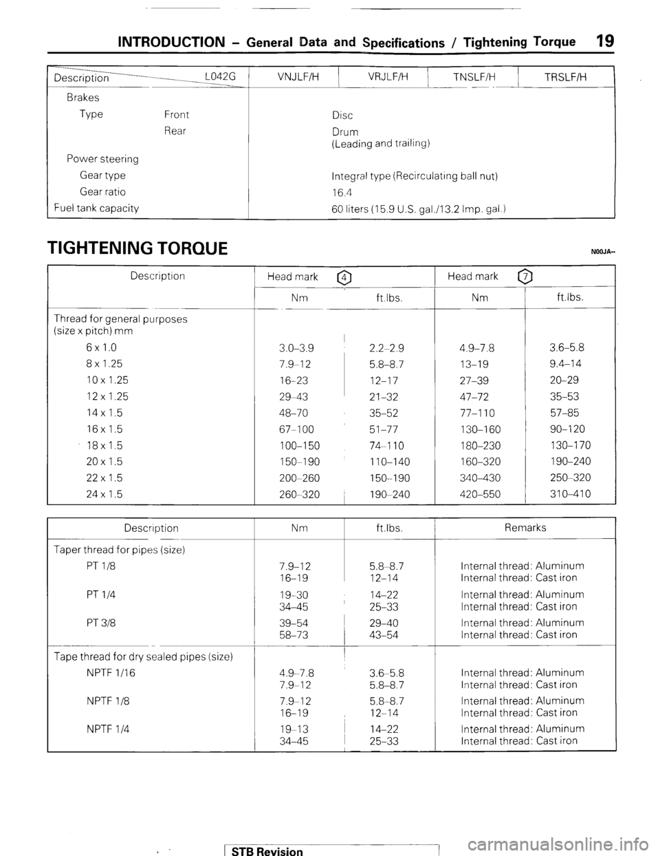
TIGHTENING TORQUE NOOJA-
Description
Thread for general purposes
(size x pitch) mm
6x 1.0
8x 1.25
10x 1.25
12 x 1.25
14x 1.5
16x 1.5
18x1.5
20x 1.5
22 x 1.5
24x 1.5 Head mark
Nm
3.0-3.9
7.9-I 2
16-23
29-43
48-70
677100
100-l 50
150-I 90
200-260
260-320 Head mark 0 7
ft.lbs. Nm ft.lbs.
I
2.2-2.9 4.9-7.8 3.6-5.8
5.8-8.7 13-19 9.4-14
12-17 27-39 20-29
21-32 47-72 35-53
35-52 77-l 10 57-85
51-77 130-I 60 90-I 20
74-I 10 180-230 130-170
1 IO-140 160-320 1 go-240
150-I 90 340-430 250-320
1 go-240 420-550 310-410
Description
Taper thread for pipes (size)
PT l/8
PT l/4
PT 318 Nm ft.lbs. Remarks
Internal thread: Aluminum
Internal thread: Cast iron
Internal thread: Aluminum
Internal thread: Cast iron
Internal thread: Aluminum
Internal thread: Cast iron
Tape thread for dry sealed pipes (size)
NPTF l/16
NPTF l/8
NPTF l/4 4.9-7.8
7.9-I 2
7.9-I 2
16-19
19-13
34-45 3.6-5.8
5.8-8.7
5.8-8.7
12-14
14-22
25-33 Internal thread: Aluminum
Internal thread: Cast iron
Internal thread: Aluminum
Internal thread: Cast iron
Internal thread: Aluminum
Internal thread: Cast iron .
) STB Revision
Page 94 of 284
8-74 CHARGING SYSTEM -Specifications
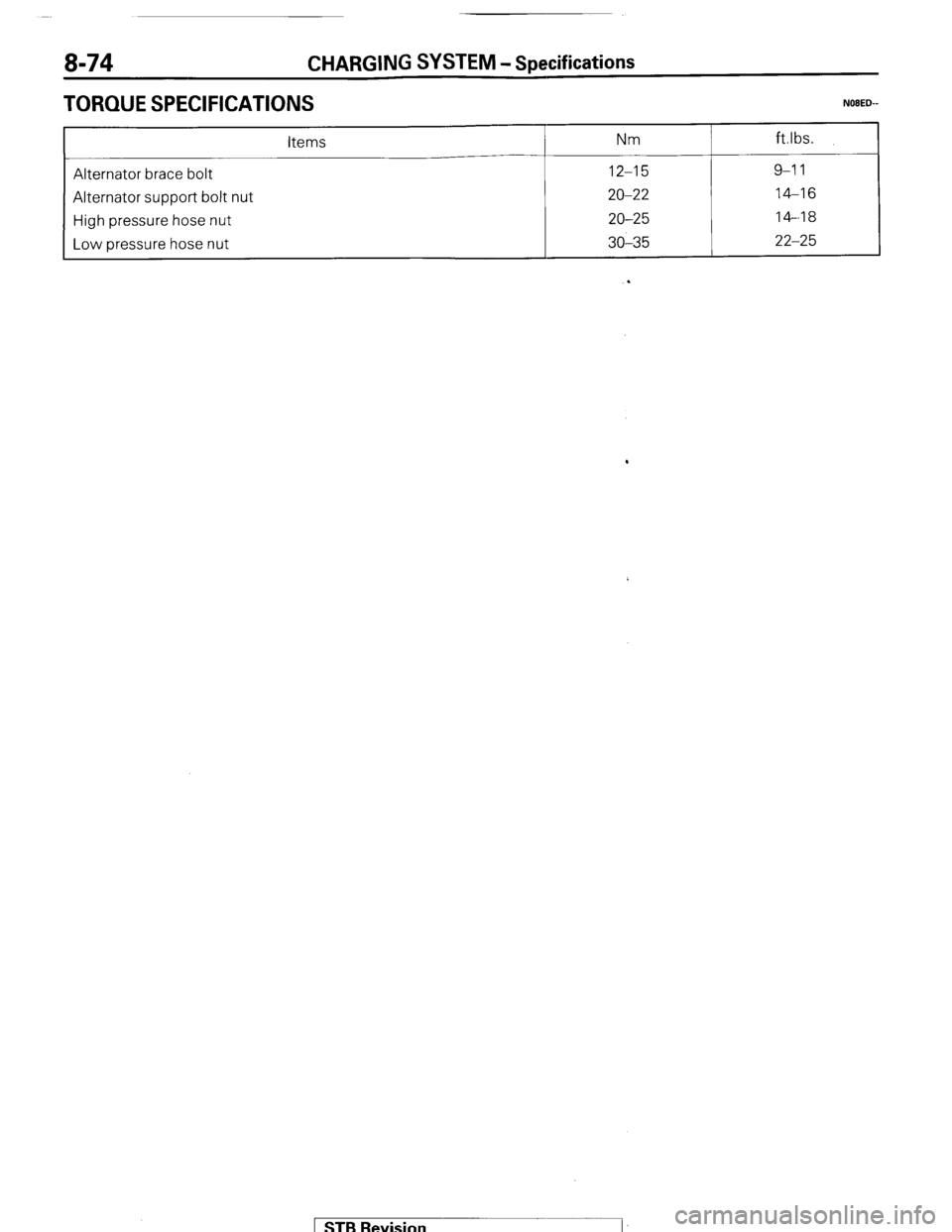
TORQUE SPECIFICATIONS
items Nm ft.lbs.
__-
Alternator brace bolt
12-15
9-l 1
Alternator support bolt nut
20-22
14-16
High pressure hose nut
20-25
14-18
Low hose nut
pressure 30-35
22-25
.
1 STB Revision
Page 113 of 284
SPECIFICATIONS
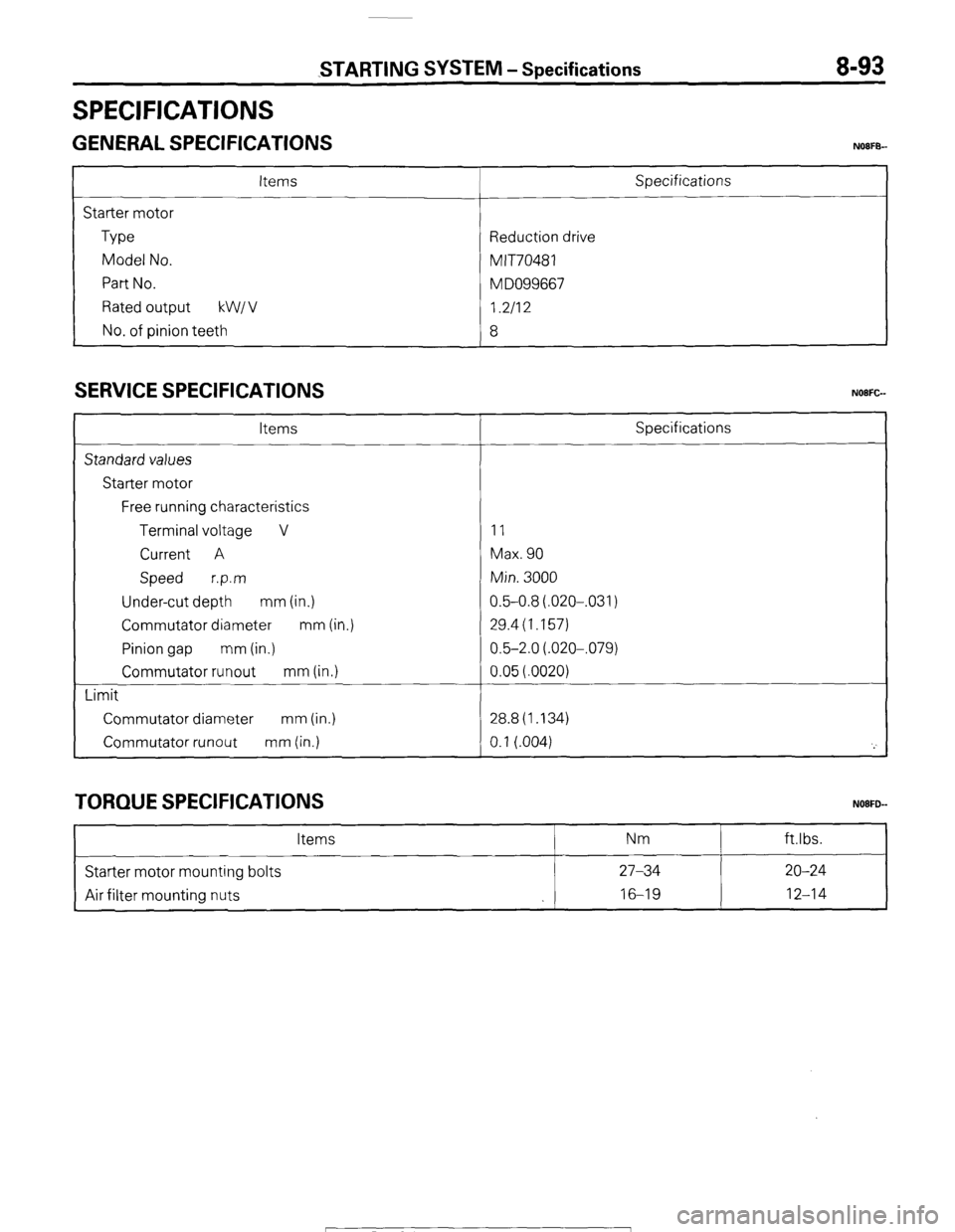
STARTING SYSTEM - Specifications 8-93
GENERAL SPECIFICATIONS NOIFB-
Items
Starter motor
Type
Model No.
Part No.
Rated output kW1 v
No. of pinion teeth Specifications
Reduction drive
MIT70481
M DO99667
I.2112
8
SERVICE SPECIFICATIONS
Items
Standard values
Starter motor
Free running characteristics
Terminal voltage V
Current A
Speed r.p.m
Under-cut depth mm (in.)
Commutator diameter mm (in.)
Pinion gap mm (in.)
Commutator runout mm (in.)
Limit
Commutator diameter mm (in.)
Commutator runout mm (in.) Specifications
11
Max. 90
Min. 3000
0.5-0.8(.020-,031)
29.4(1.157)
0.5-2.0(.020-,079)
0.05(.0020)
28.8(1.134)
0.1 (.004)
'_'
TORQUE SPECIFICATIONS
Items Nm ftlbs.
Starter motor mounting bolts 27-34 20-24
Air filter mounting nuts 16-19
12-14
1 STB Revision
Page 114 of 284
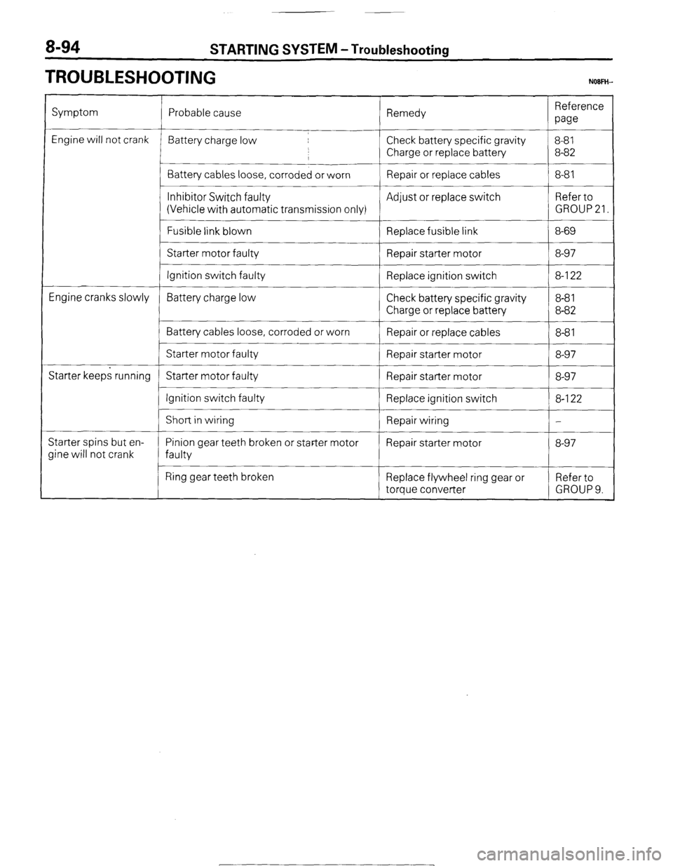
8-94 STARTING SYSTEM -Troubleshooting
TROUBLESHOOTING NOFH-
Symptom
Engine will not crank
Engine cranks slowly
Starter keeps running
Starter spins but en-
Jine will not crank Probable cause Remedy Reference
paw
Battery charge low Check battery specific gravity 8-81
,
I Charge or replace battery 8-82
Battery cables loose, corroded or worn Repair or replace cables 8-81
__~
Inhibitor Switch faulty Adjust or replace switch Refer to
(Vehicle with automatic transmission only) GROUP 21.
Fusible link blown
Replace fusible link 8-69
Starter motor faulty
Repair starter motor 8-97
Ignition switch faulty Replace ignition switch 8-l 22
Battery charge low Check battery specific gravity 8-8 1
Charge or replace battery 8-82
Battery cables loose, corroded or worn
Repair or replace cables 8-8 1
Starter motor faulty Repair starter motor 8-97
Starter motor faulty Repair starter motor 8-97
Ignition switch faulty
Replace ignition switch 8-l 22
I
Short in wiring
Repair wiring -
Pinion gear teeth broken or starter motor Repair starter motor 8-97
faulty
Ring gear teeth broken Replace flywheel ring gear or Refer to
torque converter GROUP 9.
1 STB Revision
-7
Page 128 of 284
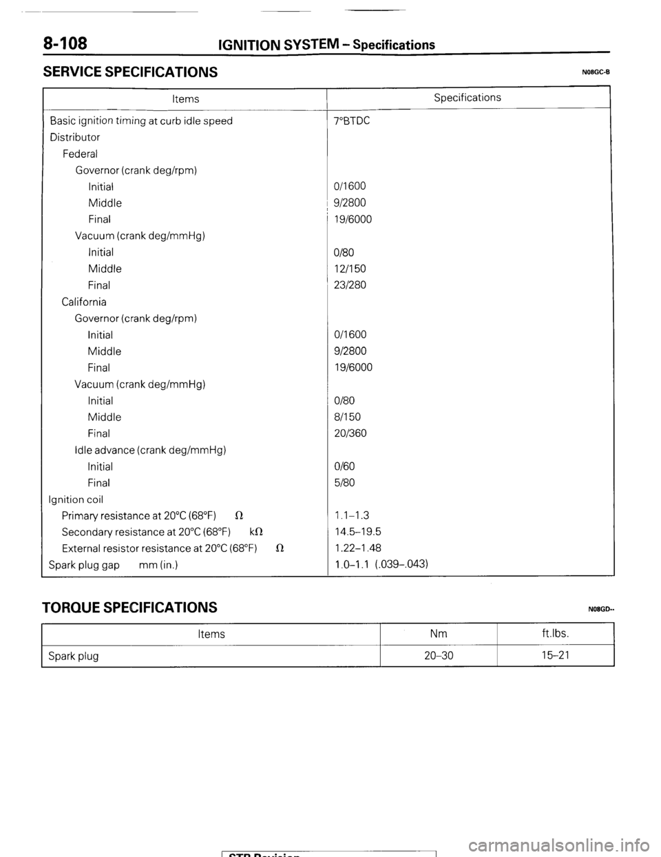
8408 IGNITION SYSTEM - Specifications
SERVICE SPECIFICATIONS
N08GC-B
Items Specifications
Basic ignition timing at curb idle speed 7”BTDC
Distributor
Federal
Governor (crank deghpm)
Initial O/l 600
Middle 1 9/2800
Final 1 g/6000
Vacuum (crank deg/mmHg)
Initial
O/80
Middle 12/I 50
Final 231280
California
Governor (crank deghpm)
initial O/l 600
Middle 912800
Final 1 g/6000
Vacuum (crank deg/mmHg)
Initial O/80
Middle 8/l 50
Final 201360
Idle advance (crank deg/mmHg)
Initial O/60
Final 5180
Ignition coil
Primary resistance at 20°C (68°F) R 1.1-1.3
Secondary resistance at 20°C (68°F) k0 14.5-19.5
External resistor resistance at 20°C (68°F) 1R 1.22-1.48
Spark plug gap mm (in.) 1.0-I .I (.039-,043)
TORQUE SPECIFICATIONS
Items Nm
NOBGD-
ft.lbs.
Spark plug 20-30 15-21
1 STB Revision
Page 145 of 284
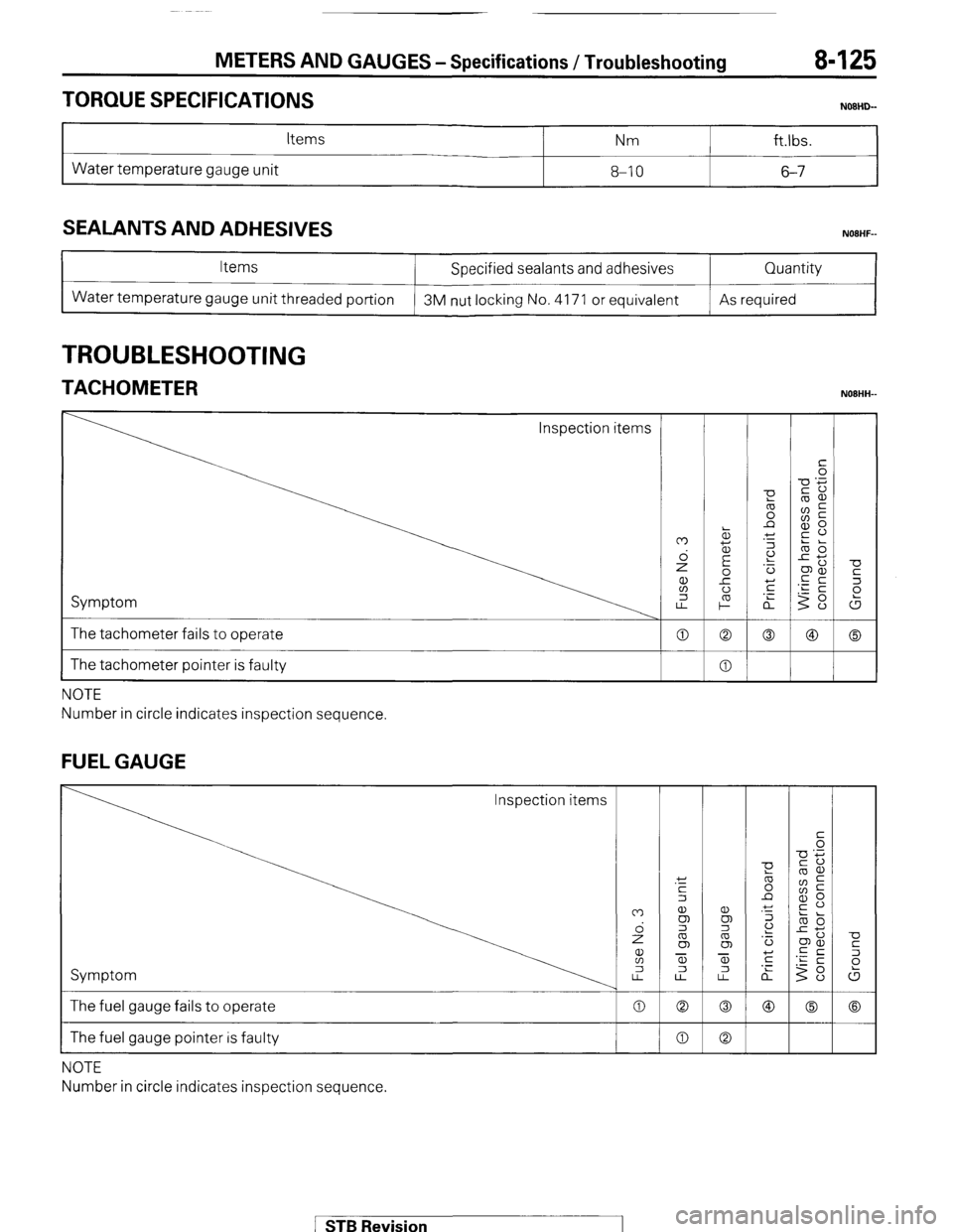
METERS AND GAUGES-Specifications /Troubleshooting 8425
TORQUE SPECIFICATIONS
Items Nm ft.lbs.
Water temperature gauge unit 8-10 6-7
SEALANTS AND ADHESIVES
Items
Water temperature gauge unit threaded portion Specified sealants and adhesives
3M nut locking No. 4171 or equivalent Quantity
As required
TROUBLESHOOTING
TACHOMETER NOBHH-
Inspection items
Symptom
The tachometer fails to operate
I The tachometer pointer is faulty
NOTE
Number in circle indicates inspection sequence.
FUEL GAUGE
Inspection items
Symptom
The fuel gauge fails to operate
The fuel gauge pointer is faulty
NOTE
Number in circle indicates inspection sequence.
1 STB Revision
Page 164 of 284
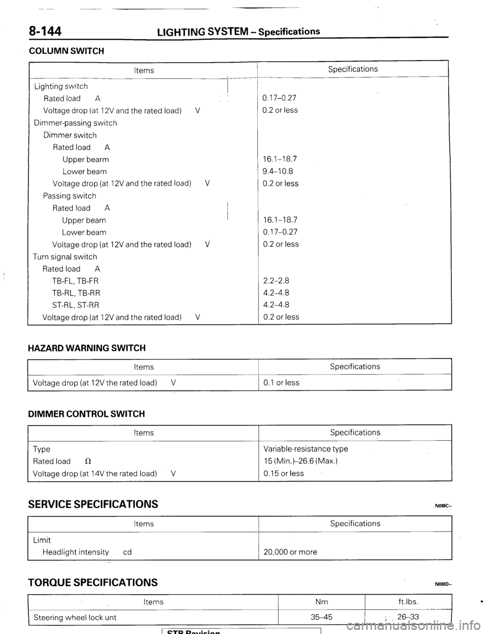
8-144
COLUMN SWITCH LIGHTING
SYSTEM -Specifications
Items Specifications
Lighting switch
Rated load A 0.17-0.27
Voltage drop (at 12V and the rated load) V 0.2 or less
Dimmer-passing switch
Dimmer switch
Rated load A
Upper bearm 16.1-18.7
Lower beam 9.4-10.8
Voltage drop (at 12V and the rated load) V 0.2 or less
Passing switch
Rated load A I
Upper beam I
16.1-18.7
Lower beam 0.17-0.27
Voltage drop (at 12V and the rated load)
V 0.2 or less
Turn signal switch
Rated load A
TB-FL, TB-FR 2.2-2.8
TB-RL, TB-R R 4.2-4.8
ST-RL, ST-RR 4.2-4.8
Voltage drop (at 12V and the rated load)
V 0.2 or less
HAZARD WARNING SWITCH
Items Specifications
I Voltage drop (at 12V the rated load) V 0.1 or less
I
DIMMER CONTROL SWITCH
Items Specifications
Type Variable-resistance type
Rated load n 15 (Min.)-26.6 (Max.)
Voltage drop (at 14V the rated load) V 0.15 or less
SERVICE SPECIFICATIONS
Items Specifications
Limit
Headlight intensity cd 20,000 or more
TORQUE SPECIFICATIONS
I
Items Nm ft.lbs.
N08lb
Steering wheel lock unt 35-45 I. 26-33
I
1 STB Revision
Page 183 of 284
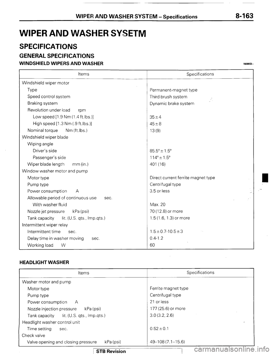
WIPER AND WASHER SYSTEM -Specifications 8-163
WIPER AND WASHER SYSETM
SPECIFICATIONS
GENERAL SPECIFICATIONS
WINDSHIELD WIPERS AND WASHER NOBKB-
Items
Windshield wiper motor
Type
Speed control system
Braking system
Revolution under load
wm
Low speed [I .9 Nm (1.4 ft.lbs.)]
High speed [I .3 Nm (.9 ftlbs.)]
Nominal torque Nm (ftlbs.)
Windshield wiper blade
Wiping angle
Driver’s side
Passenger’s side
Wiper blade length mm (in.)
Window washer motor and pump
Motor type
Pump type
Power consumption A
Allowable period of continuous use
With washer fluid
Nozzle jet pressure kPa (psi) Sbecifications
sec.
Tank capacity lit. (US. qts., Imp.qts.)
Intermittent wiper relay
Intermittent time sec.
Delay time in washer moving sec.
Working load W
HEADLIGHT WASHER
Items
Washer motor and pump
Motor type
Pump type
Power consumption A
Nozzle injection pressure kPa (psi)
Tank capacity lit. (U.S. qts., Imp.qts.)
Headlight washer control unit
Time setting sec.
Check valve
Valve opening and closing pressure kPa (psi) ‘ermanent-magnet type
Third brush system
Dynamic brake system
3524
45?8
13(g)
35.5” & 1.5”
114”51.5”
401 (16)
Iirect current ferrite magnet type
Zentrifugal type
3.5 or less
Max. 20
70 (12.8) or more
1.5 (1.6, 1.3) or more
1.5~0.7-10.5~3
0.4-I .2
60
Specifications
Ferrite magnet type
Centrifugal type
21 or less
177 (25.6) or more
3.0 (3.2, 2.6)
0.52 -+ 0.1
49-108(7.1-15.6) ,-
1 STB Revision
Page 184 of 284
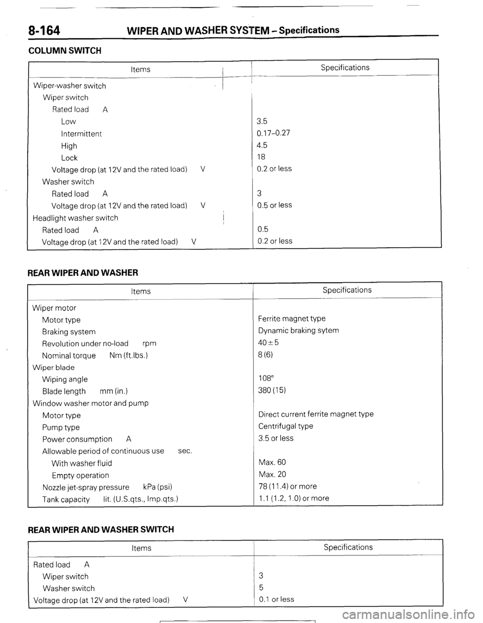
8-164 WIPER AND WASHER SYSTEM -Specifications
COLUMN SWITCH
L
Specifications
Wiper-washer switch
Wiper switch
Rated load A
Low
intermittent
High
Lock
Voltage drop (at
Washer switch
Rated load A
Voltage drop (at 2V and the rated load) V
2V and the rated load) V
/
Headlight washer switch I
Rated load A
Voltage drop (at 12V and the rated load) V
REAR WIPER AND WASHER
Items
Wiper motor
Motor type
Braking system
Revolution under no-load
m
Nominal torque Nm (ftlbs.)
Wiper blade
Wiping angle
Blade length mm (in.)
Window washer motor and pump
Motor type
Pump type
Power consumption A
Allowable period of continuous use
With washer fluid
Empty operation sec.
Nozzle jet-spray pressure kPa (psi) 78 (11.4) or more
Tank capacity lit. (U.S.qts., Imp.qts.) 1 .I (1.2, 1 .O) or more 3.5
0.17-0.27
4.5
18
0.2 or less
3
0.5 or less
0.5
0.2 or less
Specifications
Ferrite magnet type
Dynamic braking sytem
4025
8 (6)
108
380(15)
Direct current ferrite magnet type
Centrifugal type
3.5 or less
Max. 60
Max. 20
REAR WIPER AND WASHER SWITCH
Items Specifications
Rated load A
Wiper switch 3
Washer switch 5
Voltage drop (at 12V and the rated load) V 0.1 or less
1 STB Revision