clock setting MITSUBISHI MONTERO 1991 Service Manual
[x] Cancel search | Manufacturer: MITSUBISHI, Model Year: 1991, Model line: MONTERO, Model: MITSUBISHI MONTERO 1991Pages: 1333, PDF Size: 24.61 MB
Page 143 of 1333

NOTE: Fixed Speed Adjusting Screw (SAS) is preset by manufacturer
and usually does not require adjustment. Only adjust fixed
SAS if other adjustment procedures require it, or if
manufacturer's original setting has been changed.
3.0L Montero, Pickup, Ram-50, Stealth & 3000GT
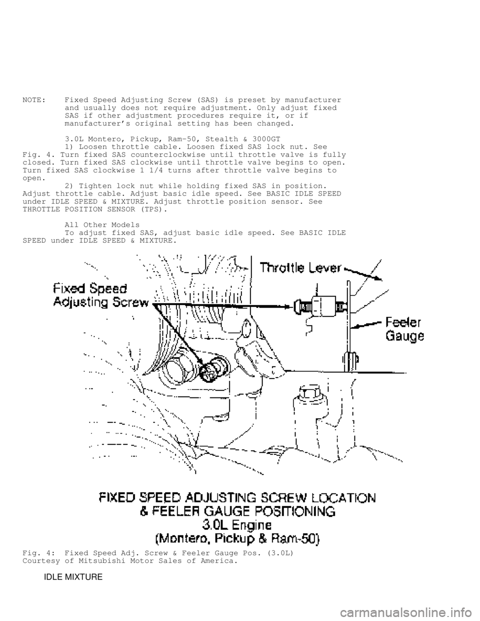
1) Loosen throttle cable. Loosen fixed SAS lock nut. See
Fig. 4. Turn fixed SAS counterclockwise until throttle valve is fully
closed. Turn fixed SAS clockwise until throttle valve begins to open.
Turn fixed SAS clockwise 1 1/4 turns after throttle valve begins to
open.
2) Tighten lock nut while holding fixed SAS in position.
Adjust throttle cable. Adjust basic idle speed. See BASIC IDLE SPEED
under IDLE SPEED & MIXTURE. Adjust throttle position sensor. See
THROTTLE POSITION SENSOR (TPS).
All Other Models
To adjust fixed SAS, adjust basic idle speed. See BASIC IDLE
SPEED under IDLE SPEED & MIXTURE.
Fig. 4: Fixed Speed Adj. Screw & Feeler Gauge Pos. (3.0L)
Courtesy of Mitsubishi Motor Sales of America.
IDLE MIXTURE
Page 146 of 1333

Adjusting Screw (SAS) and throttle lever. See Fig. 4. Loosen TPS
mounting screws. Rotate TPS fully counterclockwise. Check for
continuity between Yellow/Red wire and Black wire terminals of TPS.
3) Rotate TPS clockwise until ohmmeter registers no
continuity. Tighten TPS mounting screws. Reconnect TPS electrical
connector.
4) Use a digital voltmeter to backprobe terminal No. 19
(Brown/Red wire) and terminal No. 24 (Brown wire) at Engine Control
Unit (ECU) wiring harness on SOHC vehicles, or terminal No. 64
(Brown/Red wire) and terminal No. 72 (Black wire) on DOHC vehicles.
Turn ignition on. DO NOT start engine. Check TPS output voltage.
5) If TPS output voltage is 0.4-1.0 volt, go to step 6). If
TPS output voltage is not 0.4-1.0 volt, check TPS and wiring harness
for damage or malfunction. Replace TPS or repair wiring harness if
necessary and go to step 6).
6) Remove feeler gauge. Turn ignition off. Disconnect
voltmeter from ECU connector. Operate engine at idle for about 5
minutes to ensure engine idles smoothly and within specification.
IDLE POSITION SWITCH
NOTE: Idle position switch is preset by manufacturer. Adjustment
is usually not necessary. If other procedures in this
article require adjustment of idle position switch or if
switch setting has been changed, adjust switch as follows.
1.6L Mirage, 2.0L Eclipse & 2.0L Galant (DOHC)
1) Loosen throttle cable. Disconnect electrical connector
from idle position switch. See Fig. 5. Loosen lock nut at base of
switch. Turn switch counterclockwise until throttle valve is fully
closed.
2) Connect ohmmeter between switch terminal and switch body
(ground). Turn idle position switch clockwise until ohmmeter registers\
continuity. At this point, throttle valve should begin to open.
3) Turn switch 15/16 of a turn beyond contact point. Tighten
lock nut at base of idle position switch, holding switch to prevent it
from turning while tightening.
4) Adjust throttle cable. Adjust basic idle speed. See BASIC
IDLE SPEED. Adjust TPS. See TPS ADJUSTMENT.
All Other Models
Idle position switch is incorporated in ISC motor and is
automatically adjusted when TPS is adjusted. See TPS ADJUSTMENT.
Fig. 5: Idle Position Switch Location (1.6L & 2.0L (VIN R &U))
Courtesy of Mitsubishi Motor Sales of America.
Page 1177 of 1333

specification, use the following trouble shooting guide.
* Hydraulic Pressure High In All Ranges
Check throttle cable adjustment. If adjustment is okay, check
for throttle valve or regulator valve failure.
* Hydraulic Pressure Low In All Ranges
Check throttle cable adjustment. If adjustment is okay, check
for throttle valve, regulator valve, transmission oil pump or
overdrive clutch failure.
* Hydraulic Pressure Low In Drive Position
Check for fluid leaks in Drive hydraulic circuit. Check for
forward clutch or overdrive clutch failure.
* Hydraulic Pressure Low In Reverse Position
Check for fluid leaks in Reverse hydraulic circuit. Check for
transmission No. 3 brake failure, forward clutch failure or
overdrive clutch failure.
LINE PRESSURE (PICKUP)
1) Incorrect throttle pressure setting will cause incorrect
line pressure readings even though line pressure adjustment is
correct. Always inspect and correct throttle pressure adjustment
before adjusting line pressure.
2) Approximate adjustment, measured from valve body to inner
edge of adjusting nut, is 15/16". However, due to manufacturing
tolerances, adjustment can be varied to obtain correct line pressure.
3) Adjusting screw may be turned with an Allen wrench. One
complete turn of adjusting screw changes closed throttle line pressure
approximately 1 2/3 psi. Turn adjusting screw counterclockwise to
increase pressure or clockwise to decrease pressure.
THROTTLE PRESSURE (PICKUP)
1) Throttle pressures cannot be accurately tested. If a
malfunction exists, adjustment should be measured.
2) Insert Gauge Pin (C-3763) between throttle lever cam and
kickdown valve. Push in on tool to compress kickdown valve against its
spring.
3) As force is being exerted to compress spring, turn
throttle lever screw with Allen wrench until head of screw touches
throttle lever tang with gauge pin, and throttle valve bottoms. Ensure
adjustment is made with spring fully compressed and valve bottomed in
valve body.
KICKDOWN BAND
PICKUP
1) Locate kickdown band adjusting screw on left side of
transmission case. Loosen lock nut, and back off nut 5 turns. Ensure
adjusting screw turns freely in transmission case.
2) Using torque wrench, tighten adjusting screw to 72 INCH
lbs. (8 N.m). Back off adjusting screw 2 7/8 turns. Hold adjuster
screw in this position, and tighten lock nut to 30 ft. lbs. (41 N.m).
LOW-REVERSE BAND
PICKUP
1) Raise vehicle, drain transmission, and remove oil pan.
Loosen adjusting screw lock nut, and back off nut 5 turns. Ensure