MITSUBISHI MONTERO 1998 Service Manual
Manufacturer: MITSUBISHI, Model Year: 1998, Model line: MONTERO, Model: MITSUBISHI MONTERO 1998Pages: 1501, PDF Size: 25.81 MB
Page 1481 of 1501
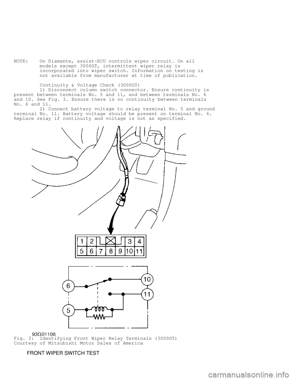
NOTE: On Diamante, assist-ECU controls wiper circuit. On all
models except 3000GT, intermittent wiper relay is
incorporated into wiper switch. Information on testing is
not available from manufacturer at time of publication.
Continuity & Voltage Check (3000GT)
1) Disconnect column switch connector. Ensure continuity is
present between terminals No. 5 and 11, and between terminals No. 6
and 10. See Fig. 3. Ensure there is no continuity between terminals
No. 6 and 11.
2) Connect battery voltage to relay terminal No. 5 and ground
terminal No. 11. Battery voltage should be present on terminal No. 6.
Replace relay if continuity and voltage is not as specified.
Fig. 3: Identifying Front Wiper Relay Terminals (3000GT)
Courtesy of Mitsubishi Motor Sales of America
FRONT WIPER SWITCH TEST
Page 1482 of 1501
NOTE: Front wiper switch is part of combination switch on steering
column. For diagnosis, see STEERING COLUMN SWITCHES article.
REAR WIPER MOTOR TEST
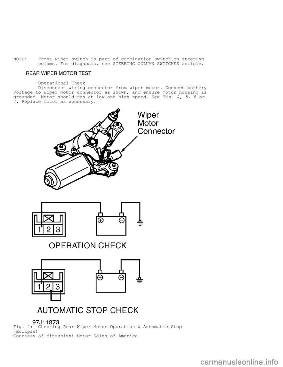
Operational Check
Disconnect wiring connector from wiper motor. Connect battery
voltage to wiper motor connector as shown, and ensure motor housing is
grounded. Motor should run at low and high speed. See Fig. 4, 5, 6 or
7. Replace motor as necessary.
Fig. 4: Checking Rear Wiper Motor Operation & Automatic Stop
(Eclipse)
Courtesy of Mitsubishi Motor Sales of America
Page 1483 of 1501
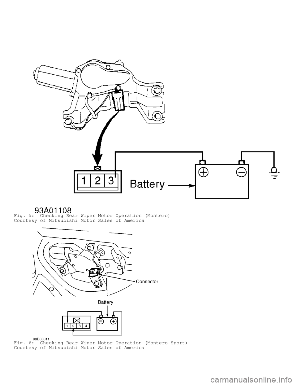
Fig. 5: Checking Rear Wiper Motor Operation (Montero)
Courtesy of Mitsubishi Motor Sales of America
Fig. 6: Checking Rear Wiper Motor Operation (Montero Sport)
Courtesy of Mitsubishi Motor Sales of America
Page 1484 of 1501
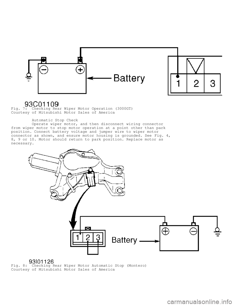
Fig. 7: Checking Rear Wiper Motor Operation (3000GT)
Courtesy of Mitsubishi Motor Sales of America
Automatic Stop Check
Operate wiper motor, and then disconnect wiring connector
from wiper motor to stop motor operation at a point other than park
position. Connect battery voltage and jumper wire to wiper motor
connector as shown, and ensure motor housing is grounded. See Fig. 4,
8, 9 or 10. Motor should return to park position. Replace motor as
necessary.
Fig. 8: Checking Rear Wiper Motor Automatic Stop (Montero)
Courtesy of Mitsubishi Motor Sales of America
Page 1485 of 1501
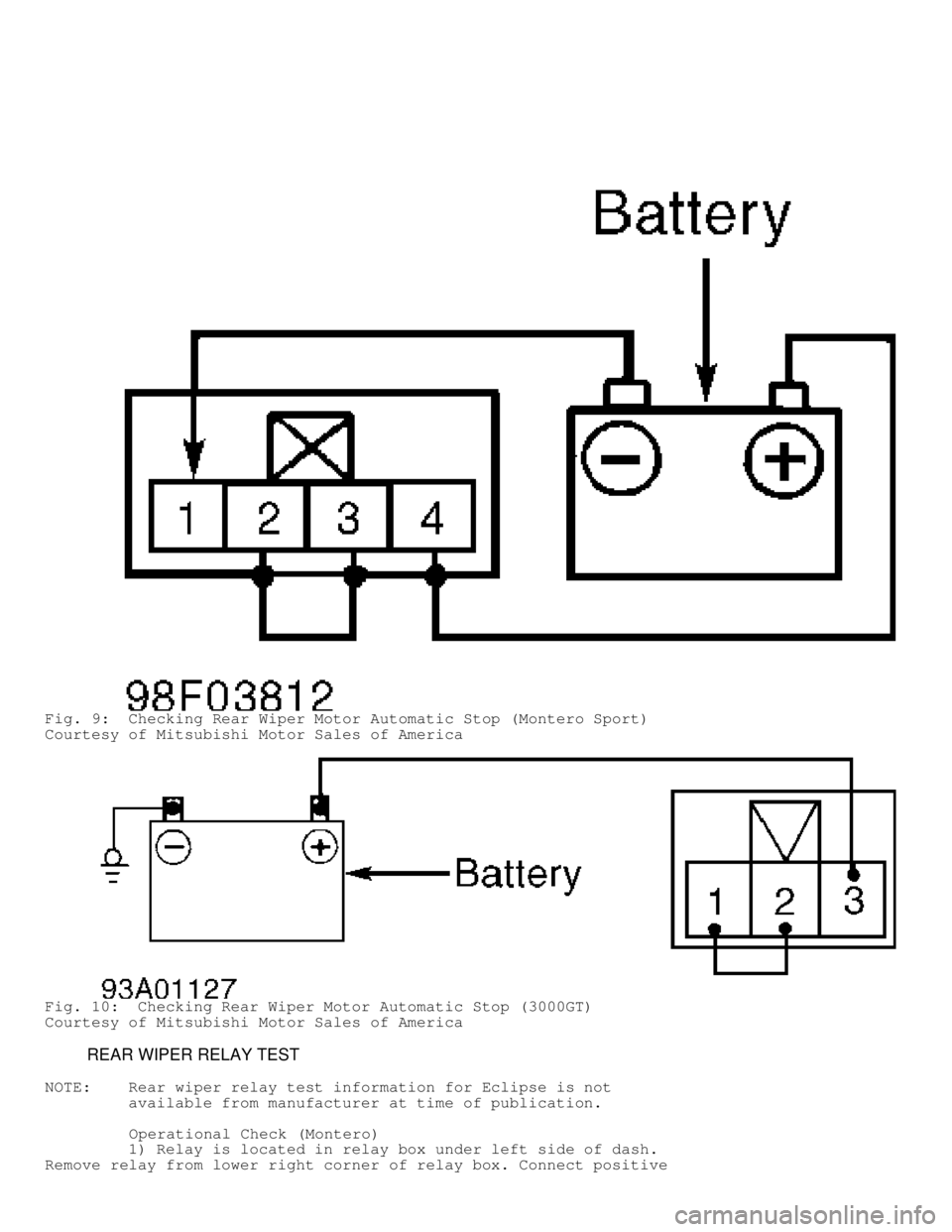
Fig. 9: Checking Rear Wiper Motor Automatic Stop (Montero Sport)
Courtesy of Mitsubishi Motor Sales of America
Fig. 10: Checking Rear Wiper Motor Automatic Stop (3000GT)
Courtesy of Mitsubishi Motor Sales of America
REAR WIPER RELAY TEST
NOTE: Rear wiper relay test information for Eclipse is not
available from manufacturer at time of publication.
Operational Check (Montero)
1) Relay is located in relay box under left side of dash.
Remove relay from lower right corner of relay box. Connect positive
Page 1486 of 1501
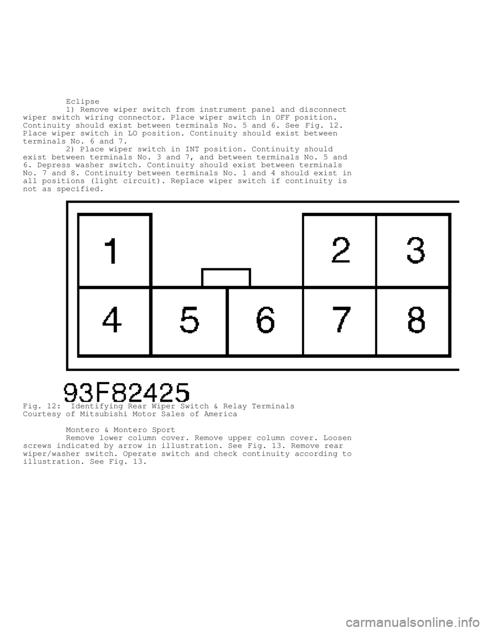
voltmeter lead to terminal No. 2. Connect negative voltmeter lead to
terminal No. 7. Ensure battery voltage is present, when battery
voltage is connected to terminals No. 4 and 8, and terminal No. 7 is
grounded. See Fig. 12.
2) With voltmeter connected to terminals No. 2 and 7, ensure
battery voltage is present for intermittent periods of 8 seconds when
positive battery terminal is connected to terminals No. 4 and 5, and
negative battery terminal is connected to terminal No. 7.
3) With voltmeter connected to terminals No. 2 and 7, ensure
battery voltage is present when positive battery terminal is connected
to terminals No. 4 and 6, and negative battery terminal is connected
to terminal No. 7. Replace relay if voltage is not as specified.
Operational Check (Montero Sport)
1) Relay is located in relay box under left side of dash.
Remove relay from lower left corner of relay box. Check for continuity
between terminals No. 1 and 2. See Fig. 12. Continuity should exist.
2) Connect terminals No. 4 and 5 to positive battery
terminal. Ensure battery voltage is present at terminal No. 2 for
intermittent periods of 8 seconds when terminal No. 7 is connected to
negative battery terminal. Replace relay if voltage is not as
specified.
Operational Check (3000GT)
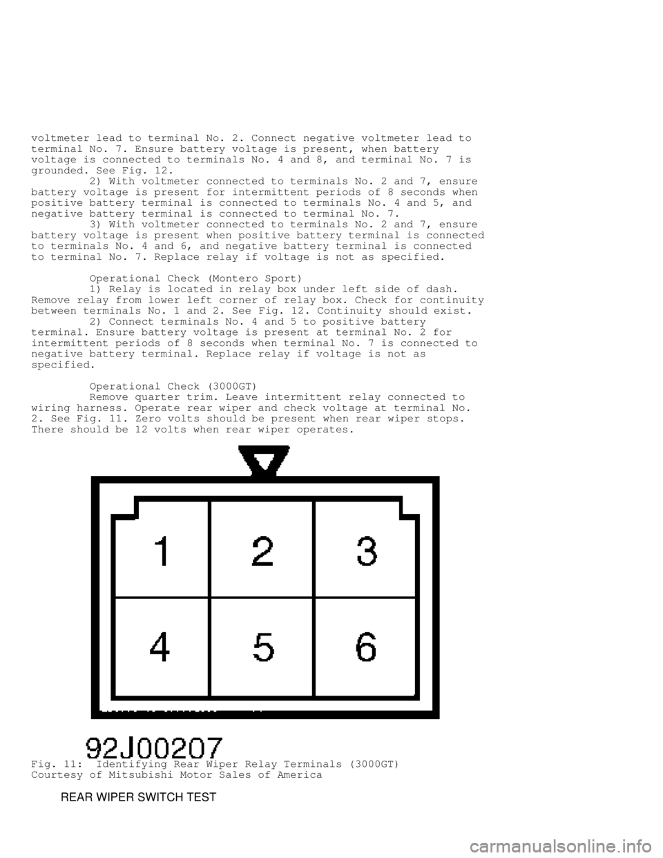
Remove quarter trim. Leave intermittent relay connected to
wiring harness. Operate rear wiper and check voltage at terminal No.
2. See Fig. 11. Zero volts should be present when rear wiper stops.
There should be 12 volts when rear wiper operates.
Fig. 11: Identifying Rear Wiper Relay Terminals (3000GT)
Courtesy of Mitsubishi Motor Sales of America
REAR WIPER SWITCH TEST
Page 1487 of 1501
Eclipse
1) Remove wiper switch from instrument panel and disconnect
wiper switch wiring connector. Place wiper switch in OFF position.
Continuity should exist between terminals No. 5 and 6. See Fig. 12.
Place wiper switch in LO position. Continuity should exist between
terminals No. 6 and 7.
2) Place wiper switch in INT position. Continuity should
exist between terminals No. 3 and 7, and between terminals No. 5 and
6. Depress washer switch. Continuity should exist between terminals
No. 7 and 8. Continuity between terminals No. 1 and 4 should exist in
all positions (light circuit). Replace wiper switch if continuity is
not as specified.
Fig. 12: Identifying Rear Wiper Switch & Relay Terminals
Courtesy of Mitsubishi Motor Sales of America
Montero & Montero Sport
Remove lower column cover. Remove upper column cover. Loosen
screws indicated by arrow in illustration. See Fig. 13. Remove rear
wiper/washer switch. Operate switch and check continuity according to
illustration. See Fig. 13.
Page 1488 of 1501
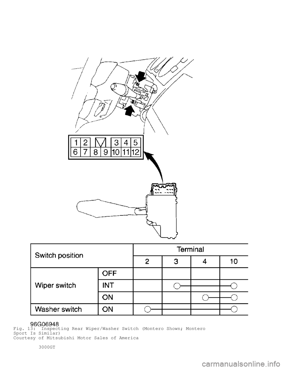
Fig. 13: Inspecting Rear Wiper/Washer Switch (Montero Shown; Montero
Sport Is Similar)
Courtesy of Mitsubishi Motor Sales of America
3000GT
Page 1489 of 1501

1) Remove wiper switch from instrument panel and disconnect
wiper switch. Place wiper switch in OFF position. Continuity should
exist between terminals No. 4 and 5. See Fig. 12. Place wiper switch
in ON position. Continuity should exist between terminals No. 5 and 6.
2) Place wiper switch in INT position. Continuity should
exist between terminals No. 4 and 5, and between terminals No. 7 and
8. Depress washer switch. Continuity should exist between terminals
No. 2 and 6. Continuity between terminals No. 1 and 3 should exist in
all positions (light circuit).
REMOVAL & INSTALLATION
FRONT WIPER MOTOR
Removal & Installation
Remove wiper motor bolts. Pull motor out slightly. Disconnect
wiper linkage from motor assembly and remove motor. To install,
reverse removal procedure.
FRONT WIPER SWITCH
NOTE: Front wiper switch is part of combination switch on steering
column. See STEERING COLUMN SWITCHES article.
REAR WIPER MOTOR
Removal & Installation
Remove wiper blade and arm assembly. Remove tailgate trim, 2
bolts and wiper motor. To install, reverse removal procedure. Ensure
grommet is in good condition.
REAR WIPER SWITCH
Removal & Installation
Pry rear wiper switch from instrument panel and disconnect
wiper switch wiring connector. To install switch, reverse removal
procedure.
WIRING DIAGRAMS
Page 1490 of 1501
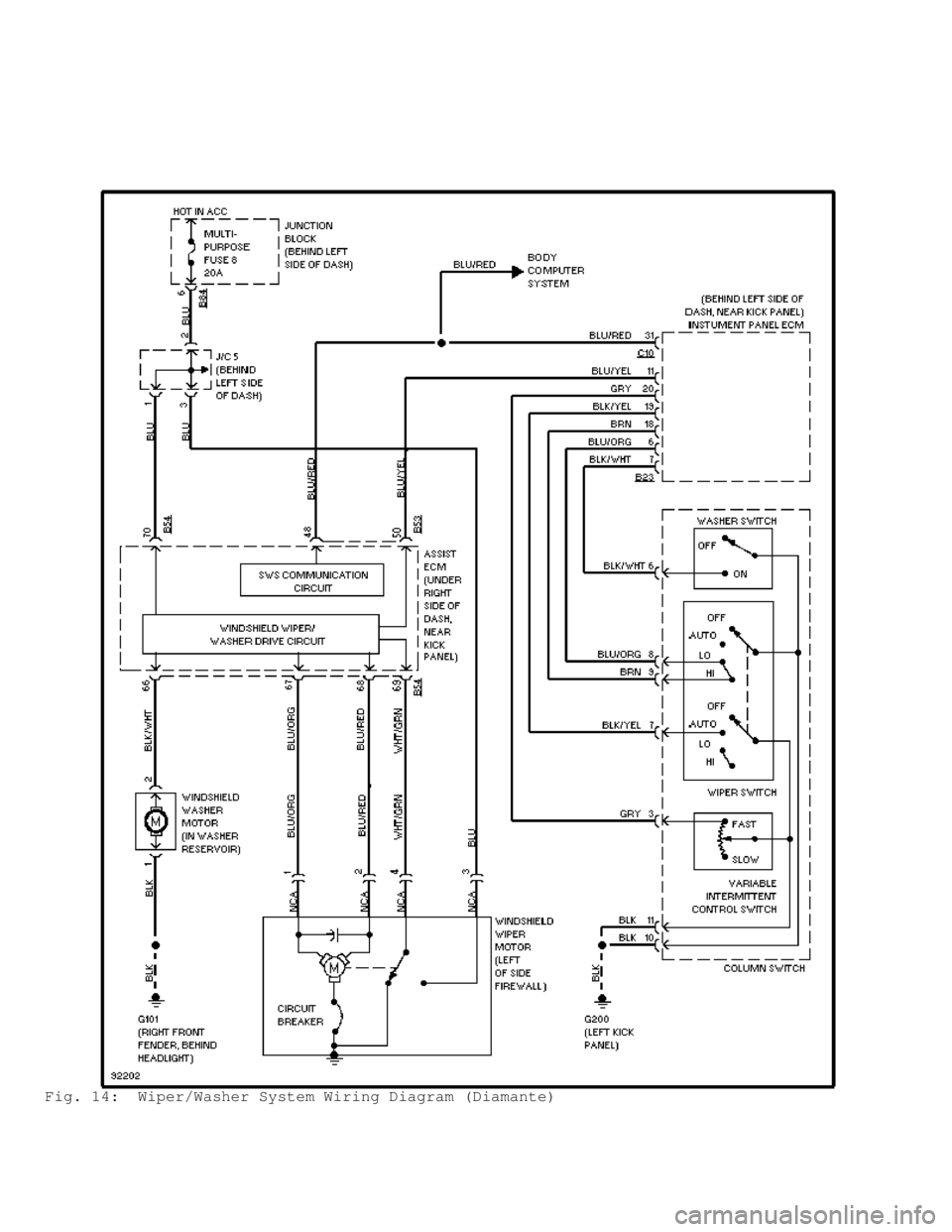
Fig. 14: Wiper/Washer System Wiring Diagram (Diamante)