engine MITSUBISHI MONTERO 1998 Service Manual
[x] Cancel search | Manufacturer: MITSUBISHI, Model Year: 1998, Model line: MONTERO, Model: MITSUBISHI MONTERO 1998Pages: 1501, PDF Size: 25.81 MB
Page 1248 of 1501

profit organizations. MAP conducted pilot programs in twelve states
before announcing the program nationally in October, 1998. During the
pilots, participating repair shops demonstrated their adherence to the
Pledge and Standards and agreed to follow the UICS in communicating
the results of their inspection to their customers. To put some
"teeth" in the program, an accreditation requirement for shops was
initiated. The requirements are stringent, and a self-policing method
has been incorporated which includes the "mystery shopping" of
outlets.
We welcome you to join us as we continue our outreach... with
your support, both the automotive repair industry and your customers
will reap the benefits. Please visit MAP at our Internet site www.
motorist.org or contact us at:
1444 I Street, NW Suite 700
Washington, DC 20005
Phone (202) 712-9042 Fax (202) 216-9646
January 1999
MAP UNIFORM INSPECTION GENERAL GUIDELINES
OVERVIEW OF SERVICE REQUIREMENTS & SUGGESTIONS
It is MAP policy that all exhaust, brake, steering,
suspension, wheel alignment, drive-line, engine performance and
maintenance, and heating, ventilation and air conditioning, and
electrical services be offered and performed under the standards and
procedures specified in these sections.
Before any service is performed on a vehicle, an inspection
of the appropriate system must be performed. The results of this
inspection must be explained to the customer and documented on an
inspection form. The condition of the vehicle and its components will
indicate what services/part replacements may be "Required" or
"Suggested". In addition, suggestions may be made to satisfy the
requests expressed by the customer.
When a component is suggested or required to be repaired or
replaced, the decision to repair or replace must be made in the
customer's best interest, and at his or her choice given the options
available.
This section lists the various parts and conditions that
indicate a required or suggested service or part replacement.
Although this list is extensive, it is not fully inclusive. In
addition to this list, a technician may make a suggestion. However,
any suggestions must be based on substantial and informed experience,
or the vehicle manufacturer's recommended service interval and must be
documented.
Some conditions indicate that service or part replacement is
required because the part in question is no longer providing the
function for which it is intended, does not meet a vehicle
manufacturer's design specification or is missing.
Example:
An exhaust pipe has corroded severely and has a hole in it
through which exhaust gases are leaking. Replacement of the
exhaust pipe in this case is required due to functional
failure.
Example:
A brake rotor has been worn to the point where it measures
less than the vehicle manufacturer's discard specifications.
Replacement of the rotor is required because it does not meet
design specifications.
Page 1302 of 1501
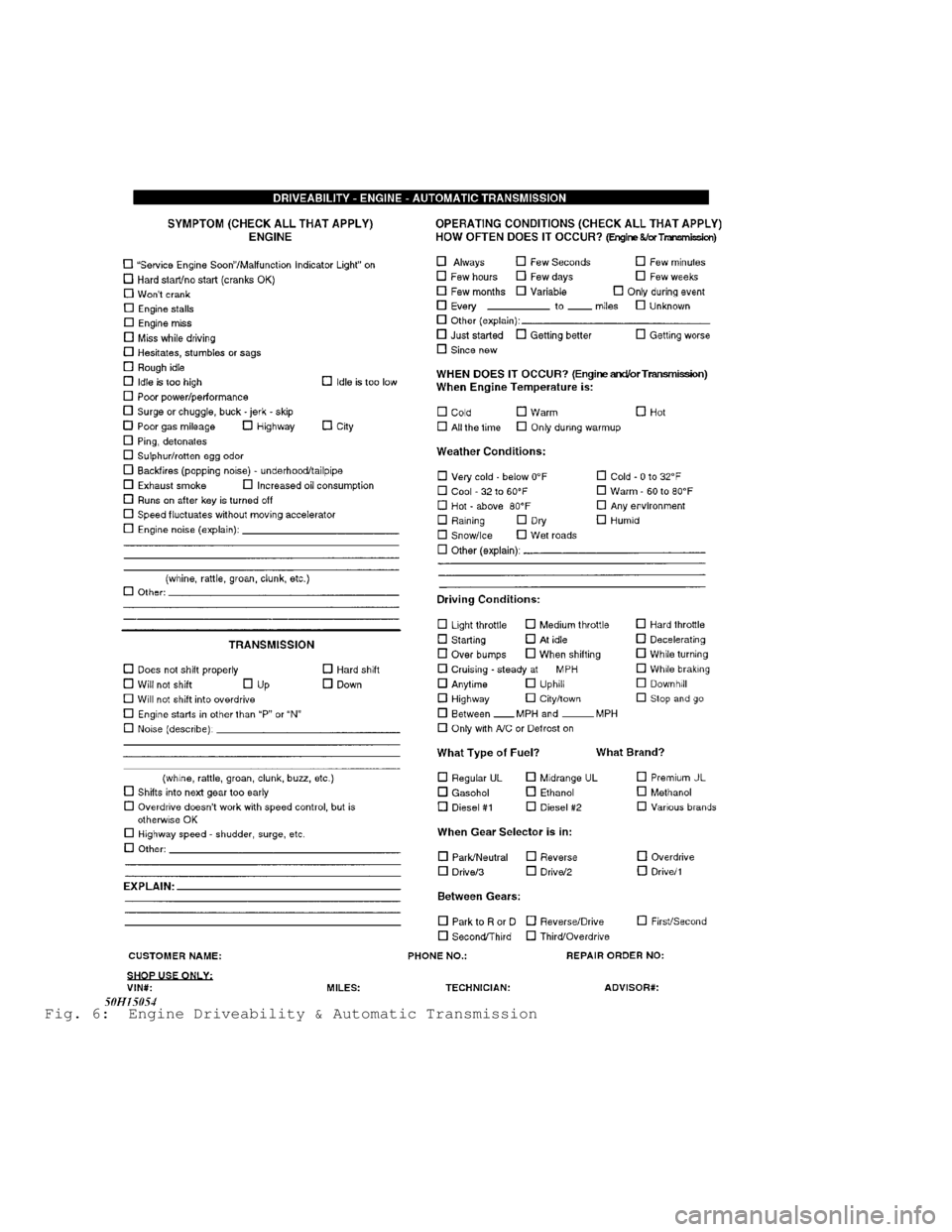
Fig. 6: Engine Driveability & Automatic Transmission
Page 1316 of 1501
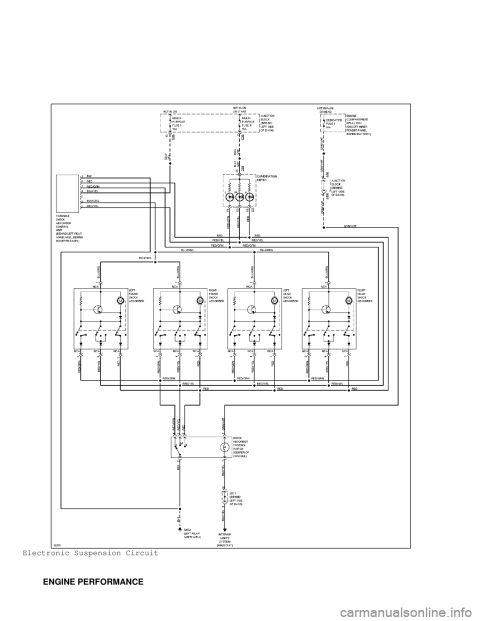
Electronic Suspension Circuit
ENGINE PERFORMANCE
Page 1317 of 1501
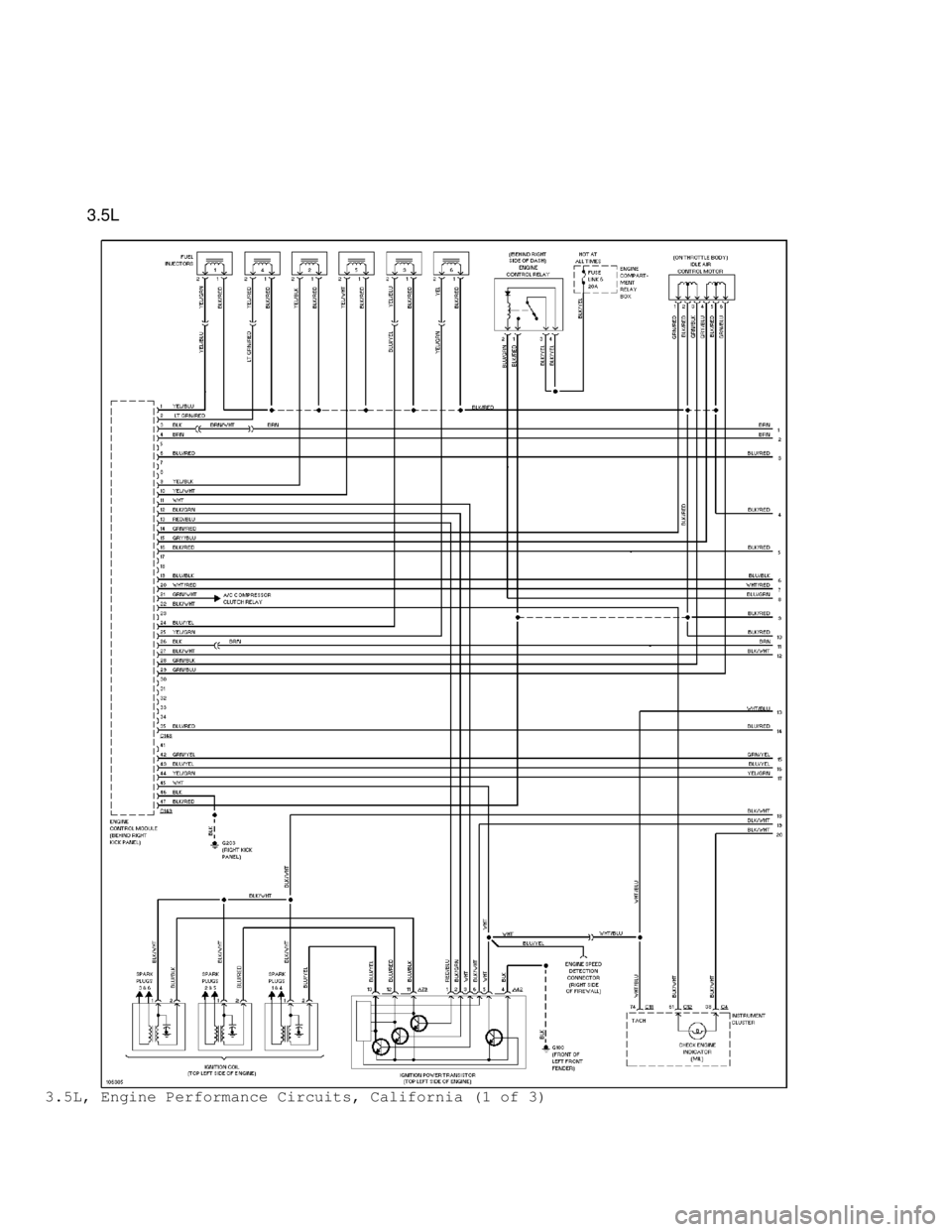
3.5L
3.5L, Engine Performance Circuits, California (1 of 3)
Page 1318 of 1501
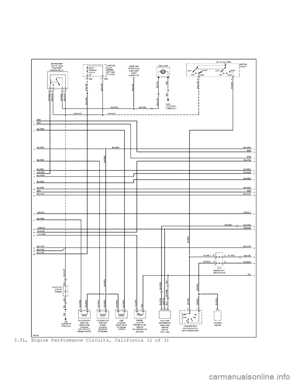
3.5L, Engine Performance Circuits, California (2 of 3)
Page 1319 of 1501
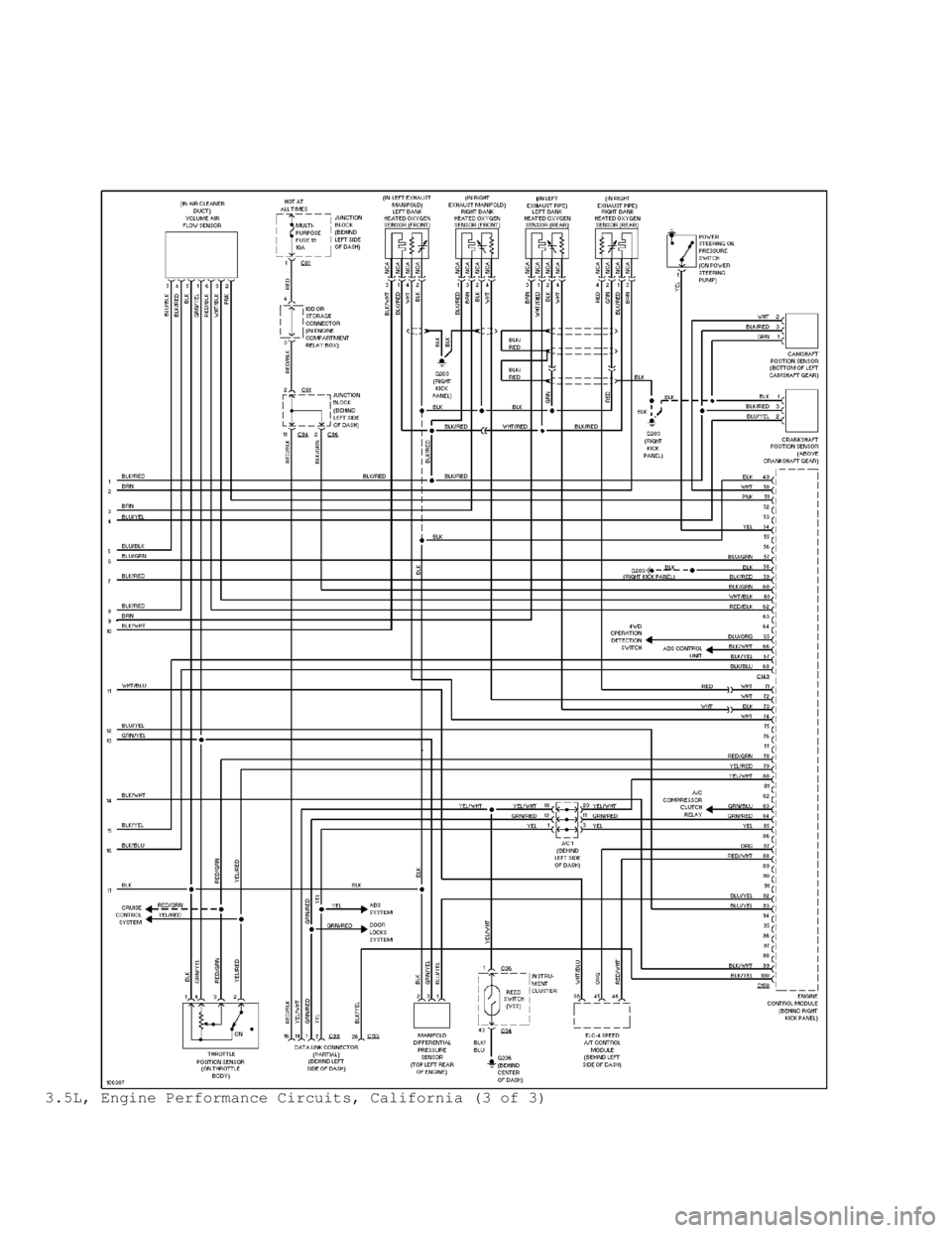
3.5L, Engine Performance Circuits, California (3 of 3)
Page 1320 of 1501
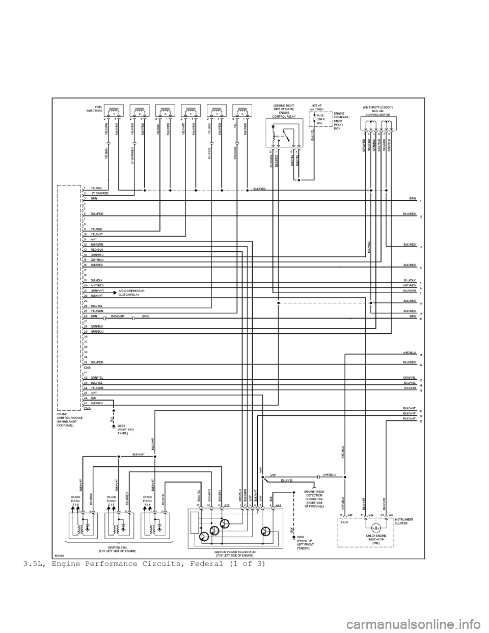
3.5L, Engine Performance Circuits, Federal (1 of 3)
Page 1321 of 1501
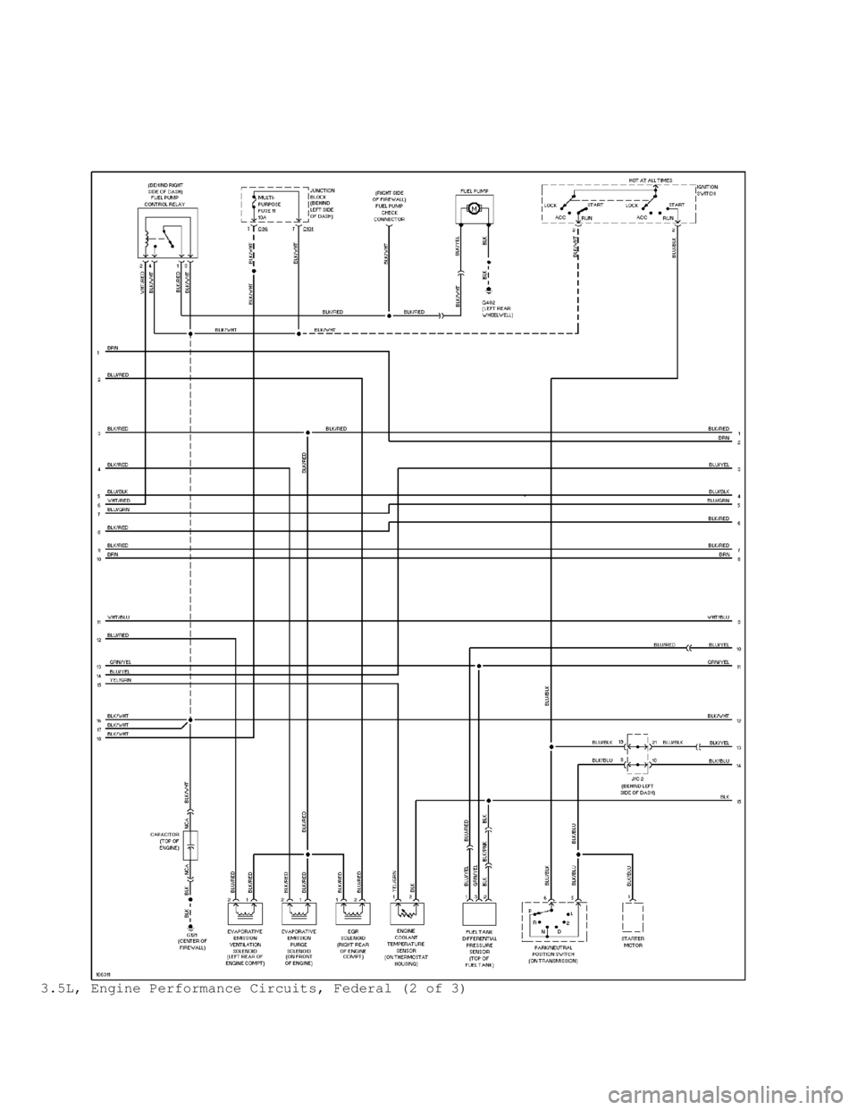
3.5L, Engine Performance Circuits, Federal (2 of 3)
Page 1322 of 1501
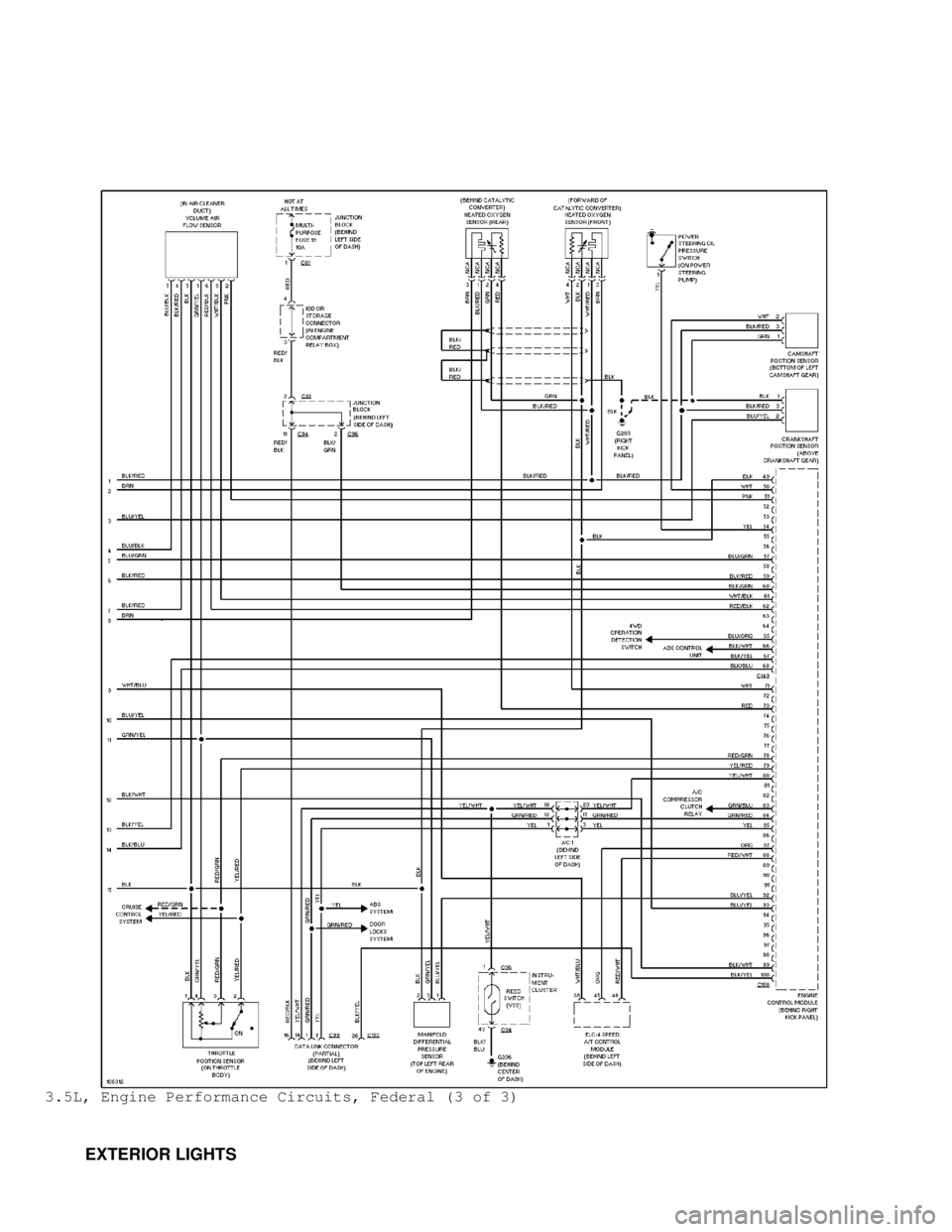
3.5L, Engine Performance Circuits, Federal (3 of 3)
EXTERIOR LIGHTS
Page 1354 of 1501

TRANSMISSION REMOVAL & INSTALLATION - A/T
1998 Mitsubishi Montero
1997-98 TRANSMISSION SERVICING
Mitsubishi Transmission Removal & Installation
Diamante, Eclipse, Galant, Mirage, Montero, 3000GT
REMOVAL & INSTALLATION
AWD & FWD MODELS
Removal
1) On all models except Galant, remove battery and battery
tray. On 3000GT, remove washer tank. On all models, remove air cleaner
cover with air inlet hose assembly. Raise and support vehicle. Remove
wheels. Remove undercover(s) (if equipped). Disconnect control cable\
s
at transaxle. Drain transaxle fluid.
2) On AWD models, remove front exhaust pipe. On all models,
disconnect neutral safety switch connector, oil cooler hoses and
electrical connectors from transaxle. Disconnect speedometer cable and
throttle control cable (if equipped). Remove starter motor.
3) Separate tie rod end. Separate lower ball joint. Separate
stabilizer bar connection (if necessary). Remove axle shafts. See
appropriate AXLE SHAFTS article in DRIVE AXLES. Remove center
crossmember assembly.
4) On AWD models, separate transfer assembly from transaxle.
Reference mark transfer assembly-to-drive shaft and remove transfer
assembly.
5) On all models, remove transmission inspection (dust)
cover. Place index mark on torque converter and drive plate for
reassembly reference. Remove torque converter-to-drive plate bolts.
Push torque converter away from engine into transaxle.
6) On all 4-cylinder models, support engine. On all models,
support transaxle with jack. Remove bolts from transaxle mounts.
Remove mounting brackets and remaining transaxle-to-engine bolts.
Slide transaxle assembly to right and lower to remove.
CAUTION: Ensure torque converter is fully seated in transaxle before
installation. Always install new snap rings on inner
constant velocity joints.
Installation
1) To install, reverse removal procedure. Tighten transaxle-
to-engine bolts and torque converter-to-drive plate bolts to
specification. See TORQUE SPECIFICATIONS .
2) Ensure reference marks on torque converter-to-drive plate
and transfer assembly-to-drive shaft align. Tighten mounting bolts
with weight of engine and transaxle on mounts. Refill transaxle fluid
to specified level. See LUBRICATION in TRANSMISSION SERVICING - A/T
article. Adjust all control cables. See ADJUSTMENTS in
TRANSMISSION SERVICING - A/T article.
RWD & 4WD MODELS
Removal
1) Disconnect negative battery cable. On Montero 4WD, remove
transfer case shift lever knob, dust boot and retainer plate or
console. Remove transfer case gearshift assembly.
2) On all models, raise and support vehicle. Remove
undercarriage cover and/or skid plate(s). Drain transmission and
transfer case (if applicable). Place reference mark on drive shaft(s)\