fuel MITSUBISHI MONTERO 2000 Service Repair Manual
[x] Cancel search | Manufacturer: MITSUBISHI, Model Year: 2000, Model line: MONTERO, Model: MITSUBISHI MONTERO 2000Pages: 1839, PDF Size: 29.19 MB
Page 1630 of 1839

CHASSIS ELECTRICAL -Clock or Center Display54A-60
Terminal
No.Input/
OutputSignal symbolTerminal
voltage (V)Wiring harness
problemTrouble symptom caused by wiring
harness problem
Open
circuitShort
circuit
15Input/
OutputKHi: System
voltage
Lo: 0-1ExistsExistsValues on trip information screen (average
vehicle speed, fuel consumption and
cruising distance) are abnormal. Commu-
nication is impossible between the
engine-ECU and the MUT-II.
16------
17Input/
OutputM-BUSY
(AUDIO)Hi: 4-5
Lo: 0-1ExistsExistsAudio display does not appear. Panel
switch cannot be operated for audio unit.
Nighttime illumination does not appear for
audio unit.
18-SHIELD-GND----
19Input/
OutputM-BUSY
(A/C)Hi: 4-5
Lo: 0-1ExistsExistsA/C display does not appear.
Outside air temperature does not appear
20-SHIELD-GND----
21, 22------
23InputEX-TEMPExistsExistsOutside air temperature does not appear.
24InputILL+Hi: System
voltageExists-Nighttime illumination does not appear for
audio units.
Lo: 0-1
-ExistsBlown multipurpose fuse.
25InputACC (ACCSystem volt-Exists-Screen display does not appear.
power supply)age
-ExistsBlown multipurpose fuse.
26Input+BSystem volt-Exists-Screen display does not appear.
age
-ExistsBlown multipurpose fuse.
27InputVSSHi: System
voltage
Lo: 0-1ExistsExistsAbnormal outside air temperature ap-
pears.
(only diesel-powered vehicles)
28-GND (earth)-Exists-Screen display does not appear.
29, 30------
31-GND-TEMPExistsExistsOutside air temperature does not appear.
32InputILL -ExistsExistsThe display screen can not be dimmed.
33InputFUEL GAUGE-ExistsAbnormal cruising distance appears.
34, 35------
36InputIG1Hi: System
voltageExists-Communication with engine-ECU is im-
possible. Abnormal driving data values
appear.
-ExistsCommunication with engine-ECU is im-
possible. Abnormal driving data values
appear. Blown multipurpose fuse.
www.WorkshopManuals.co.uk
Purchased from www.WorkshopManuals.co.uk
Page 1631 of 1839

CHASSIS ELECTRICAL -Clock or Center Display54A-61
INSPECTION CHART CLASSIFIED BY TROUBLE SYMPTOMS
Related unitTrouble SymptomInspection pro-
cedure No.Reference
page
Malfunction of center
display, related sen-No display appears after the ignition key is turned to the
ACC position.154A-62
sors, and wiring har-
nesses
Outside air temperature does not appear or abnormal
outside air temperature appears.254A-62
Abnormal vehicle speed is displayed on the service
mode.354A-63
Abnormal driving data are displayed:
D
Abnormal average fuel consumption (momentary
fuel consumption) and average vehicle speed
D
Abnormal cruising distance454A-64
Clock runs fast or slow.554A-64
The display screen is dim.654A-65
Air conditioning display does not apper.754A-66
www.WorkshopManuals.co.uk
Purchased from www.WorkshopManuals.co.uk
Page 1634 of 1839
CHASSIS ELECTRICAL -Clock or Center Display54A-64
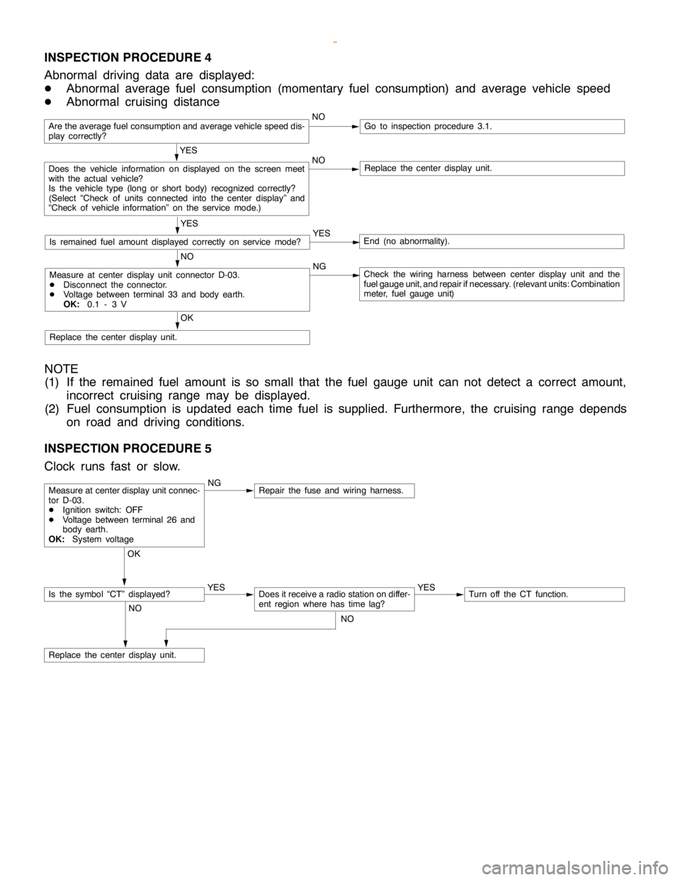
INSPECTION PROCEDURE 4
Abnormal driving data are displayed:
DAbnormal average fuel consumption (momentary fuel consumption) and average vehicle speed
DAbnormal cruising distance
Are the average fuel consumption and average vehicle speed dis-
play correctly?NOGo to inspection procedure 3.1.
YES
Does the vehicle information on displayed on the screen meet
with the actual vehicle?
Is the vehicle type (long or short body) recognized correctly?
(Select “Check of units connected into the center display” and
“Check of vehicle information” on the service mode.)NOReplace the center display unit.
YES
Is remained fuel amount displayed correctly on servicemode?YESEnd (no abnormality).
NO
Measure at center display unit connector D-03.
DDisconnect the connector.
DVoltage between terminal 33 and body earth.
OK:0.1 - 3 VNGCheck the wiring harness between center display unit and the
fuel gauge unit, and repair ifnecessary. (relevant units: Combination
meter, fuel gauge unit)
OK
Replace the center display unit.
NOTE
(1) If the remained fuel amount is so small that the fuel gauge unit can not detect a correct amount,
incorrect cruising range may be displayed.
(2) Fuel consumption is updated each time fuel is supplied. Furthermore, the cruising range depends
on road and driving conditions.
INSPECTION PROCEDURE 5
Clock runs fast or slow.
NGRepair the fuse and wiring harness.
OK
YES
Does it receive a radio station on differ-
ent region where has timelag?YESTurn off the CT function.
NO
Replace the center display unit.
Measure at center display unit connec-
tor D-03.
DIgnition switch: OFF
DVoltage between terminal 26 and
body earth.
OK:System voltage
Is the symbol “CT” displayed?
NO
www.WorkshopManuals.co.uk
Purchased from www.WorkshopManuals.co.uk
Page 1679 of 1839
CHASSIS ELECTRICAL -RV MeterCHASSIS ELECTRICAL -RV MeterCHASSIS ELECTRICAL -RV Meter54A-18
Termi-Input/out-
t
Signal sym-
bl
Terminal
lt
Harness problemTrouble symptoms when there is a
hblnal No.
p
put
gy
bolvoltage
(V)Open
circuitshort-cir-
cuit
yp
harness problem
29 - 30––––––
31–EARTH
(TEMP)––––
32–ILL - (illumi-
nation lamp
adjustment
signal)–ExistsExistsUnable to adjust illumination lamp
33InputFUEL
GAUGE0-3ExistsExists–
34 - 36––––––
CHART CLASSIFIED BY TROUBLE SYMPTOMS
Related unitTrouble SymptomInspection
procedure
No.Refer-
ence
page
Malfunction of RV meterNo system operations can be carried out.154A-18
System voltage drop warning screen appears.254A-18
Ambient temperature does not display normally.354A-19
Compass does not display normally.454A-20
Altimeter does not display normally.554A-21
Air conditioner information does not display normally.654A-21
Audio information does not display normally.754A-22
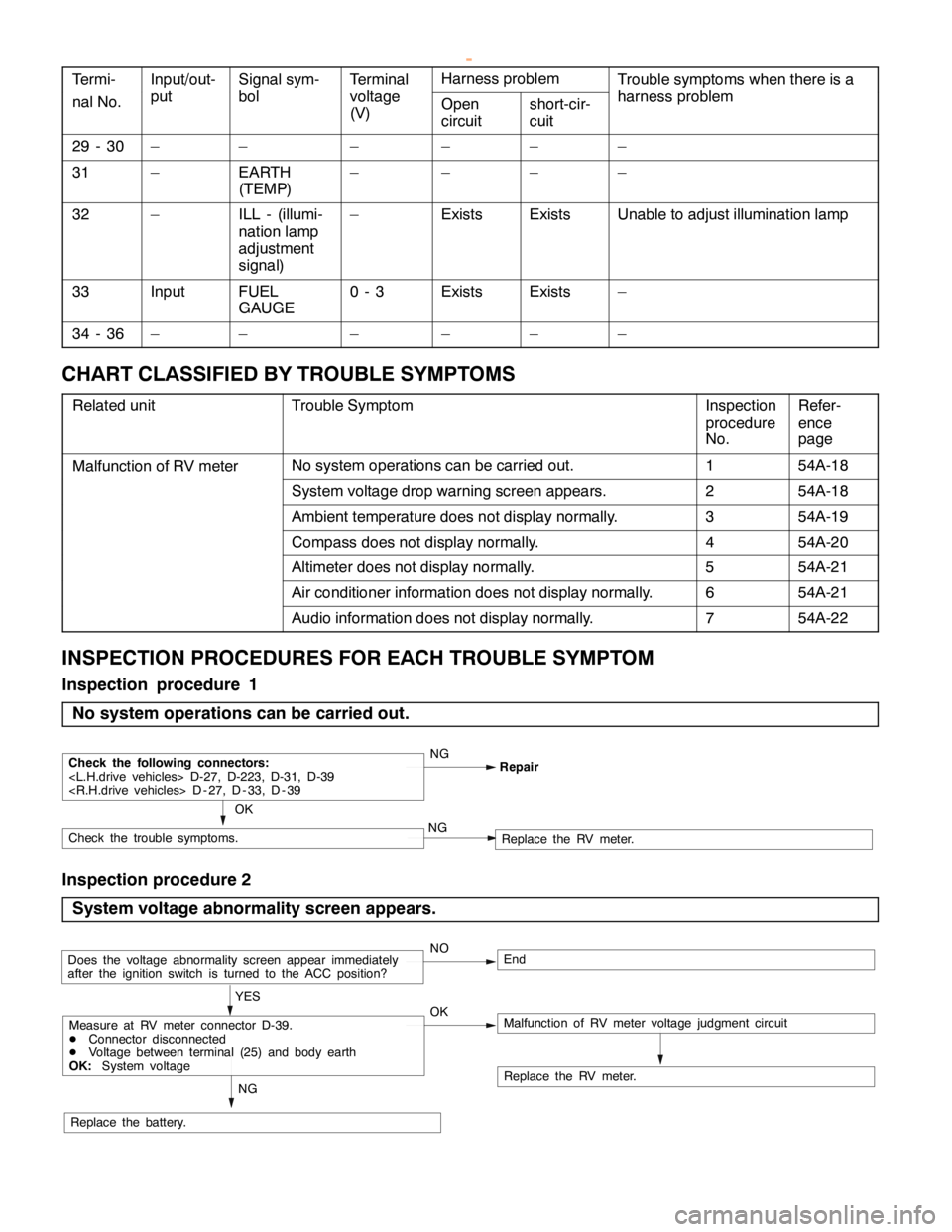
INSPECTION PROCEDURES FOR EACH TROUBLE SYMPTOM
Inspection procedure 1
No system operations can be carried out.
NG
OK
Check the following connectors:
Check the trouble symptoms.NGReplace the RV meter.
Inspection procedure 2
System voltage abnormality screen appears.
NOEnd
OK YES
Replace the battery.
Replace the RV meter.
NG
Does the voltage abnormality screen appear immediately
after the ignition switch is turned to the ACC position?
Malfunction of RV meter voltage judgment circuitMeasure at RV meter connector D-39.
DConnector disconnected
DVoltage between terminal (25) and body earth
OK:System voltage
www.WorkshopManuals.co.uk
Purchased from www.WorkshopManuals.co.uk