egr valve MITSUBISHI MONTERO 2000 Service Repair Manual
[x] Cancel search | Manufacturer: MITSUBISHI, Model Year: 2000, Model line: MONTERO, Model: MITSUBISHI MONTERO 2000Pages: 1839, PDF Size: 29.19 MB
Page 216 of 1839

13A-2
GASOLINE DIRECT
INJECTION (GDI)
CONTENTS
GENERAL INFORMATION 3..................
SERVICE SPECIFICATIONS 7.................
SEALANT 7..................................
SPECIAL TOOLS 7..........................
TROUBLESHOOTING
TROUBLESHOOTING 126.............
ON-VEHICLE SERVICE 219..................
Fuel Pump Connector Disconnection (How to
Reduce the Fuel Pressure) 219.................
Fuel Pump Operation (Low Pressure) Check 220.
Throttle Body (Throttle Valve Area) Cleaning 220.
Throttle Position Sensor Adjustment 220.........
Accelerator Pedal Position Sensor
Adjustment 221................................
Fuel Pressure Test 222.........................
Fuel Leak Check 225...........................
Component Location 226........................
Engine Control Relay, Fuel Pump Relay, Injector
Driver Control Relay and Throttle Valve Control
Servo Relay Continuity Check 227...............Intake Air Temperature Sensor Check 227.......
Engine Coolant Temperature Sensor Check 227..
Throttle Position Sensor Check 228..............
Accelerator Pedal Position Sensor Check 229....
Accelerator Pedal Position Switch Check 230.....
Oxygen Sensor Check 230......................
Injector Check 232.............................
Throttle Valve Control Servo Check 232..........
Clutch Switch Check 233.......................
Purge Control Solenoid Valve Check 233.........
EGR Valve Check 233..........................
INJECTOR 234.............................
FUEL PUMP (HIGH PRESSURE) 239.........
THROTTLE BODY 242.......................
INJECTOR DRIVER 245.....................
ENGINE-ECU, ENGINE-A/T-ECU ,
THROTTLE VALVE CONTROLLER 246.......
www.WorkshopManuals.co.uk
Purchased from www.WorkshopManuals.co.uk
Page 218 of 1839

GDI -General Information13A-4
SELF-DIAGNOSIS FUNCTION
DWhen an abnormality is detected in one
of the sensors or actuators related to
emission control, the engine warning lamp
(check engine lamp) illuminates or flashes
as a warning to the driver.
DWhen an abnormality is detected in one
of the sensors or actuators, a diagnosis
code corresponding to the abnormality is
output.
DThe engine-ECU records the engine
operating condition when the diagnosis
code is set. This data is called “freezeframe” data.
This data can be read by using the MUT-II,
and can then be used in simulation tests
for troubleshooting.
DThe RAM data inside the engine-ECU
related to the sensors and actuators can
be read by means of the MUT-II. In addition,
the actuators can be force-driven under
certain circumstances.
OTHER CONTROL FUNCTIONS
1. Fuel Pump Control
Turns the fuel pump relay ON so that current
is supplied to the fuel pump while the engine
is cranking or running.
2. A/C Relay Control
Turns the compressor clutch of the A/C
ON and OFF.3. Purge Control Solenoid Valve Control
Refer to GROUP 17.
4. EGR Control Servo Control
Refer to GROUP 17.
GENERAL SPECIFICATIONS
ItemsSpecifications
Throttle bodyThrottle bore mm65
Throttle position sensorVariable resistor type
Throttle valve control servoBrushless DC-motor type
Engine-ECUIdentification model No.E2T79271
E2T79272
Engine-Identification model No.E2T76277
A/T-ECU
E2T76278
www.WorkshopManuals.co.uk
Purchased from www.WorkshopManuals.co.uk
Page 219 of 1839

GDI -General Information13A-5
Items Specifications
SensorsAir flow sensorKarman vortex type
Barometric pressure sensorSemiconductor type
Intake air temperature sensorThermistor type
Engine coolant temperature sensorThermistor type
Oxygen sensorZirconia type
Accelerator pedal position sensor (1st
and 2nd channels)Variable resistor type
Accelerator pedal position switchRotary contact type, within accelerator pedal position
sensor (1st channel)
Vehicle speed sensorMagnetic resistive element type
Inhibitor switchContact switch type
Camshaft position sensorHall element type
Crank angle sensorHall element type
Detonation sensorPiezoelectric type
Fuel pressure sensorMetallic membrane type
Power steering fluid pressure switchContact switch type
ActuatorsEngine control relay typeContact switch type
Fuel pump relay typeContact switch type
Injector driver control relayContact switch type
Injector type and numberElectromagnetic type, 6
Injector identification markDIM 1070
Throttle valve control servo relayContact switch type
Throttle valve control servoBrushless DC-motor type
EGR valveStepper motor type
Purge control solenoid valveDuty cycle type solenoid valve
Fuel pressure
regulator (low
pressure)Regulator pressure kPa329
Fuel pressure
regulator
(high pres-
sure)Regulator pressure MPa5.0
www.WorkshopManuals.co.uk
Purchased from www.WorkshopManuals.co.uk
Page 224 of 1839

GDI -Troubleshooting
Code No. Diagnosis item
P0206No.6 injector system
P0220LAccelerator pedal position sensor (1st channel) system
P0225LThrottle position sensor (2nd channel) system
P0300LIgnition coil (power transistor) system
P0301No.1 cylinder misfire detected.
P0302No.2 cylinder misfire detected.
P0303No.3 cylinder misfire detected.
P0304No.4 cylinder misfire detected.
P0305No.5 cylinder misfire detected.
P0306No.6 cylinder misfire detected.
P0335Crank angle sensor system
P0340Camshaft position sensor system
P0403EGR valve system
P0420Catalyst malfunction
P0443Purge control solenoid valve system
P1200Injector driver system
P1220LElectronic-controlled throttle valve system
P1221LThrottle valve position feedback system
P1222LThrottle control servo system
P1223LCommunication line system with throttle valve controller
P1225LAccelerator pedal position sensor (2nd channel) system
P1226LThrottle valve controller system
NOTE
1. If the engine warning lamp illuminates because of a malfunction of the engine-ECU, communication
between MUT-
IIand the engine-ECU is impossible. In this case, the diagnosis code cannot be read.
2. After the engine-ECU has detected a malfunction, the engine warning lamp illuminates when the
engine is next turned on and the same malfunction is re-detected. However, for items marked with
a“
L” in the diagnosis code number column, the engine warning lamp illuminates only on the first
detection of the malfunction.
If diagnosis code P0120, P0220, P0225 or P1225 is set, the engine warning lamp will flash. If the
1st and 2nd channels of the throttle postion sensor or the acccelerator pedal position sensor fail
at the same time, the engine warning lamp will also flash.
3. After the engine warning lamp illuminates, it will be switched off under the following conditions.
(1) When the engine-ECU monitored the power train malfunction three times* and met set condition
requirements, it detected no malfunction.
*: In this case, “one time” indicates from engine start to stop.
(2) For misfiring malfunction, when driving conditions (engine speed, engine coolant temperature,
etc.) are similar to those when the malfunction was first recorded.
www.WorkshopManuals.co.uk
Purchased from www.WorkshopManuals.co.uk
Page 229 of 1839

GDI -Troubleshooting
INSPECTION CHART FOR DIAGNOSIS CODES
Code No.Diagnosis itemReference page
P0100Air flow sensor system13A-17
P0105Barometric pressure sensor system13A-19
P0110Intake air temperature sensor system13A-21
P0115Engine coolant temperature sensor system13A-22
P0120LThrottle position sensor (1st channel) system13A-25
P0125Feedback system13A-27
P0130Oxygen sensor (front) system
P0135Oxygen sensor heater (front) system
P0136Oxygen sensor (rear) system
P0141Oxygen sensor heater (rear) system
P0170Abnormal fuel system13A-34
P0190LAbnormal fuel pressure13A-36
P0201No.1 injector system13A-38
P0202No.2 injector system13A-40
P0203No.3 injector system13A-42
P0204No.4 injector system13A-44
P0205No.5 injector system13A-46
P0206No.6 injector system13A-48
P0220LAccelerator pedal position sensor (1st channel) system13A-50
P0225LThrottle position sensor (2nd channel) system13A-52
P0300LIgnition coil (power transistor) system13A-53
P0301No.1 cylinder misfire detected.13A-55
P0302No.2 cylinder misfire detected.13A-55
P0303No.3 cylinder misfire detected.13A-55
P0304No.4 cylinder misfire detected.13A-55
P0305No.5 cylinder misfire detected.13A-55
P0306No.6 cylinder misfire detected.13A-55
P0325Detonation sensor system13A-56
P0335Crank angle sensor system13A-56
P0340Camshaft position sensor system13A-58
P0403EGR valve system13A-60
P0420Catalyst malfunction13A-61
www.WorkshopManuals.co.uk
Purchased from www.WorkshopManuals.co.uk
Page 249 of 1839
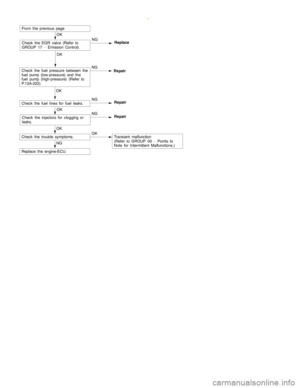
GDI -Troubleshooting
OK
Check the injectors for clogging or
leaks.NG
Repair
OK
Check the fuel lines for fuel leaks.NG
Repair
OK
Check the fuel pressure between the
fuel pump(low-pressure) and the
fuel pump (high-pressure)(Refer to
P.13A-222).NG
From the previouspage
OK
Check the trouble symptoms.OKTransient malfunction
(Refer to GROUP 00 - Points to
Note for Intermittent Malfunctions.)
NG
Replace the engine-ECU.
OK
Check the EGR valve (Refer to
GROUP 17 - Emission Control).NG
Replace
Repair
www.WorkshopManuals.co.uk
Purchased from www.WorkshopManuals.co.uk
Page 274 of 1839
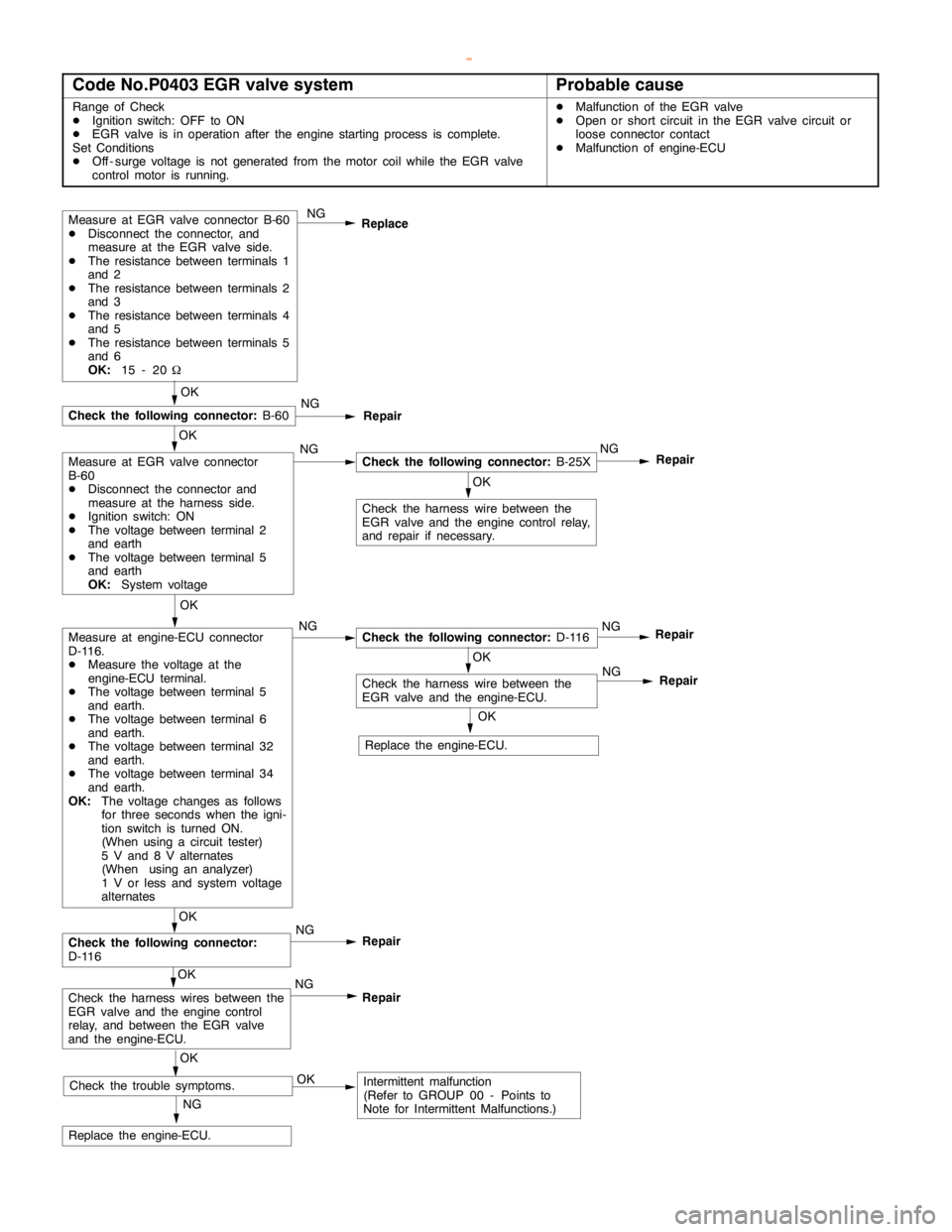
GDI -Troubleshooting
Code No.P0403 EGR valve systemProbable cause
Range of Check
DIgnition switch: OFF to ON
DEGR valve is in operation after theengine startingprocess is complete.
Set Conditions
DOff - surge voltage is not generated from the motor coil while the EGR valve
control motor is running.DMalfunction of the EGR valve
DOpen or short circuit in the EGR valve circuit or
loose connector contact
DMalfunction of engine-ECU
Measure at EGR valve connector B-60
DDisconnect the connector, and
measure at the EGR valve side.
DThe resistance between terminals 1
and 2
DThe resistance between terminals 2
and 3
DThe resistance between terminals 4
and 5
DThe resistance between terminals 5
and 6
OK:
15 - 20WNG
Replace
OK
Check the harness wire between the
EGR valve and theengine controlrelay,
and repair if necessary.
NG
Replace the engine-ECU.
OK
NG
Check the following connector:
B-25XNG
Repair
OK
Check the following connector:
B-60NG
Repair
OK
Measure at engine-ECU connector
D-116.
DMeasure the voltage at the
engine-ECU terminal.
DThe voltage between terminal 5
and earth.
DThe voltage between terminal 6
and earth.
DThe voltage between terminal 32
and earth.
DThe voltage between terminal 34
and earth.
OK:
The voltage changes as follows
for three seconds when the igni-
tion switch is turned ON.
(When using a circuit tester)
5 V and 8 V alternates
(When using an analyzer)
1 V or less and system voltage
alternatesNGCheck the following connector:
D-116NG
Repair
OK
Check the harness wire between the
EGR valve and the engine-ECU.
OK
Check the following connector:
D-116NG
Repair
OK
Check the harness wires between the
EGR valve and theengine control
relay, and between the EGR valve
and the engine-ECU.NG
Repair
OK
Check the trouble symptoms.OKIntermittent malfunction
(Refer to GROUP 00 - Points to
Note for Intermittent Malfunctions.)NG
Repair
OK
Replace the engine-ECU.
Measure at EGR valve connector
B-60
DDisconnect the connector and
measure at the harness side.
DIgnition switch: ON
DThe voltage between terminal 2
and earth
DThe voltage between terminal 5
and earth
OK:
System voltage
www.WorkshopManuals.co.uk
Purchased from www.WorkshopManuals.co.uk
Page 296 of 1839
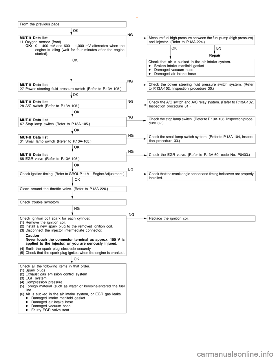
GDI -Troubleshooting
OK
Check that air is sucked in the air intake system.
DBroken intake manifold gasket
DDamaged vacuum hose
DDamaged air intake hose
From the previouspage
OK
MUT-
IIData list
27 Power steering fluid pressure switch (Refer to P.13A-105.)NGCheck the power steering fluid pressure switch system. (Refer
to P.13A-102, Inspection procedure 30.)
OK
MUT-
IIData list
28 A/C switch (Refer to P.13A-105.)NGCheck the A/C switch and A/C relay system. (Refer to P.13A-102,
Inspection procedure 31.)
OK
MUT-
IIData list
67 Stoplampswitch (Refer to P.13A-105.)NGCheck the stoplampswitch. (Refer to P.13A-103, Inspection proce-
dure 32.)
OK
MUT-
IIData list
31 Small lampswitch (Refer to P.13A-105.)NGCheck the smalllampswitch system. (Refer to P.13A-104, Inspec-
tion procedure 33.)
OK
MUT-
IIData list
68 EGR valve (Refer to P.13A-105.)NGCheck the EGR valve. (Refer to P.13A-60, code No. P0403.)
OK
NG
Check that the crankanglesensor andtiming beltcover are properly
installed.
OK
Check ignition coil spark for each cylinder.
(1) Remove the ignition coil.
(2) Install a new sparkplug to the removed ignitioncoil.
(3) Disconnect the injector intermediate connector.
Caution
Never touch the connector terminal as approx. 100 V is
applied to the injector, or you are seriously injured.
(4) Earth the sparkplug electrodesecurely.
(5) Check that the sparkplug igniteswhen theengine iscranked.NGReplace the ignition coil.
OK
Check trouble symptom.
Check all the following items in that order.
(1) Spark plugs
(2) Exhaust gas emission control system
(3) EGR system
(4) Compression pressure
(5) Foreign material (such as water or kerosine)entered the fuel
line.
(6) Air is sucked in the air intake system, or EGR gas leaks.
DDamaged intake manifoldgasket
DDamaged air intake hose
DDamaged vacuum hose
DFaulty EGR valve seat
OK
MUT-
IIData list
11 Oxygen sensor (front)
OK:
0 - 400 mV and 600 - 1,000 mV alternates when the
engine is idling(wait for four minutes after theengine
started).NG
NG
Repair
Measure fuel high-pressure between the fuel pump (highpressure)
and injector. (Refer to P.13A-224.)
Clean around the throttle valve. (Refer to P.13A-220.)
NG
Check ignition timing. (Refer to GROUP 11A - Engine Adjustment.)
www.WorkshopManuals.co.uk
Purchased from www.WorkshopManuals.co.uk
Page 298 of 1839
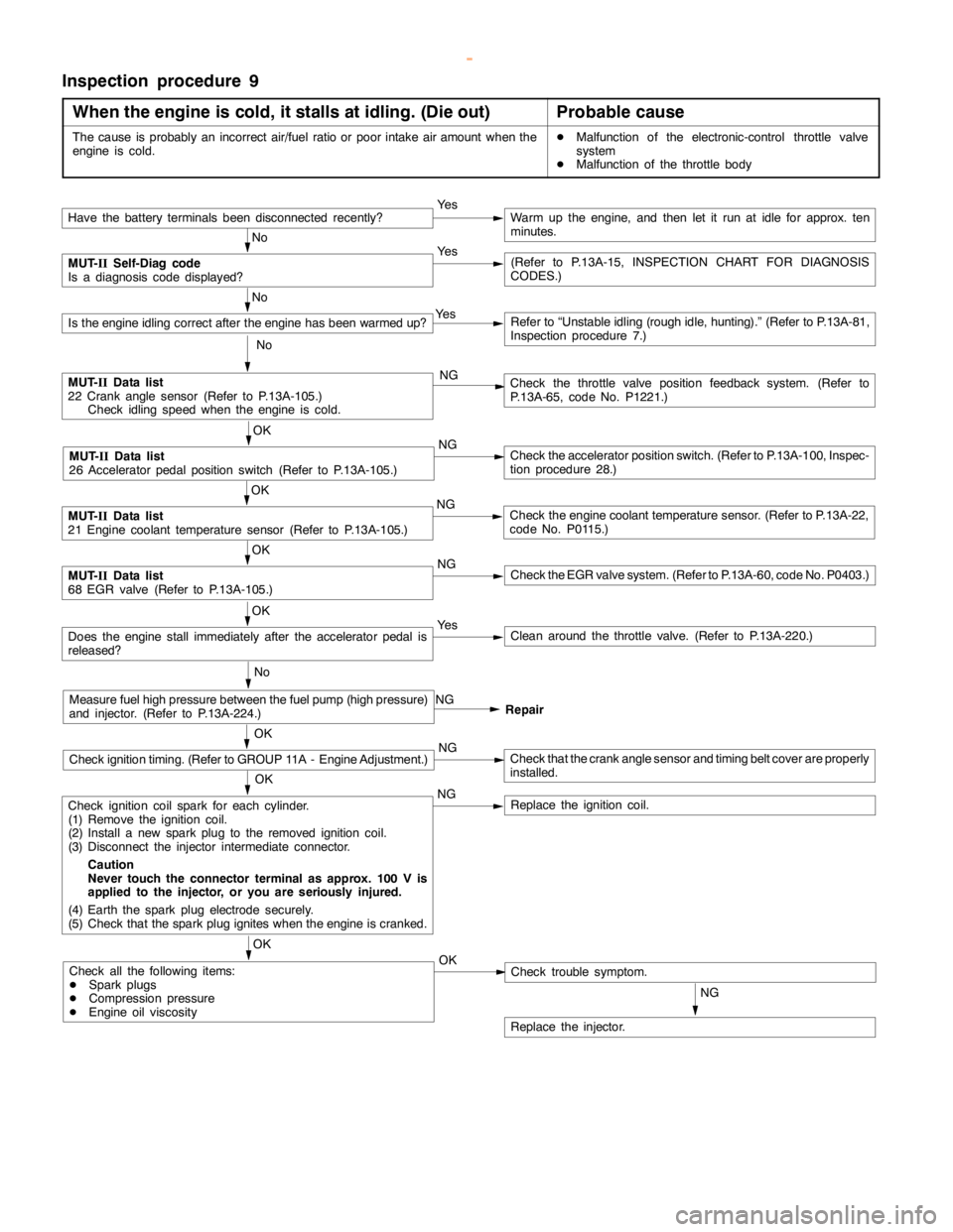
GDI -Troubleshooting
Inspection procedure 9
When the engine is cold, it stalls at idling. (Die out)
Probable cause
The cause is probably an incorrect air/fuel ratio or poor intake airamountwhen the
engine iscold.DMalfunction of the electronic-control throttle valve
system
DMalfunction of the throttle body
Have the battery terminalsbeen disconnectedrecently?Ye sWarm up the engine, and then let it run at idle for approx. ten
minutes.
No
MUT-
IISelf-Diag code
Is a diagnosis code displayed?Ye s(Refer to P.13A-15, INSPECTION CHART FOR DIAGNOSIS
CODES.)
No
Is the engine idlingcorrect after theengine has been warmed up?Ye sRefer to “Unstableidling (rough idle, hunting).”(Refer to P.13A-81,
Inspection procedure 7.)
No
MUT-
IIData list
22 Crankanglesensor (Refer to P.13A-105.)
Checkidlingspeed when theengine iscold.NGCheck the throttle valve position feedback system. (Refer to
P.13A-65, code No. P1221.)
OK
MUT-
IIData list
26 Acceleratorpedal positionswitch (Refer to P.13A-105.)NGCheck the accelerator position switch. (Refer to P.13A-100, Inspec-
tion procedure 28.)
OK
MUT-
IIData list
21 Engine coolant temperature sensor (Refer to P.13A-105.)NGCheck theengine coolant temperaturesensor. (Refer to P.13A-22,
code No. P0115.)
OK
MUT-
IIData list
68 EGR valve (Refer to P.13A-105.)NGCheck the EGR valve system. (Refer to P.13A-60, code No. P0403.)
OK
Does theenginestall immediately after the acceleratorpedal is
released?Ye sClean around the throttle valve. (Refer to P.13A-220.)
No
Measure fuel highpressure between the fuelpump (highpressure)
and injector. (Refer to P.13A-224.)NG
Repair
OK
Check ignition timing. (Refer to GROUP 11A - Engine Adjustment.)NGCheck that the crankanglesensor andtiming beltcover are properly
installed.
OK
Check ignition coil spark for each cylinder.
(1) Remove the ignition coil.
(2) Install a new sparkplug to the removed ignitioncoil.
(3) Disconnect the injector intermediate connector.
Caution
Never touch the connector terminal as approx. 100 V is
applied to the injector, or you are seriously injured.
(4) Earth the sparkplug electrodesecurely.
(5) Check that the sparkplug igniteswhen theengine iscranked.NGReplace the ignition coil.
OK
Check all the following items:
DSpark plugs
DCompression pressure
DEngine oilviscosityNGCheck trouble symptom. OK
Replace the injector.
www.WorkshopManuals.co.uk
Purchased from www.WorkshopManuals.co.uk
Page 300 of 1839
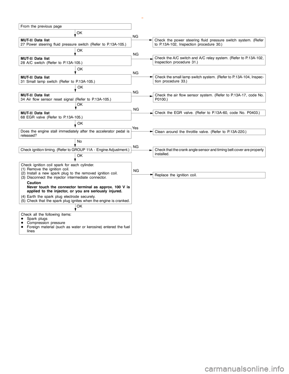
GDI -Troubleshooting
From the previouspage
OK
MUT-
IIData list
27 Power steering fluid pressure switch (Refer to P.13A-105.)NGCheck the power steering fluid pressure switch system. (Refer
to P.13A-102, Inspection procedure 30.)
OK
MUT-
IIData list
28 A/C switch (Refer to P.13A-105.)NGCheck the A/C switch and A/C relay system. (Refer to P.13A-102,
Inspection procedure 31.)
MUT-
IIData list
31 Small lampswitch (Refer to P.13A-105.)NGCheck the smalllampswitch system. (Refer to P.13A-104, Inspec-
tion procedure 33.)
OK
MUT-
IIData list
34 Air flow sensor reset signal (Refer to P.13A-105.)NGCheck the air flow sensor system. (Refer to P.13A-17, code No.
P0100.)
OK
MUT-
IIData list
68 EGR valve (Refer to P.13A-105.)NGCheck the EGR valve. (Refer to P.13A-60, code No. P0403.)
OK
Ye s
Clean around the throttle valve. (Refer to P.13A-220.)
No
NG
Check that the crankanglesensor andtiming beltcover are properly
installed.
OK
Check ignition coil spark for each cylinder.
(1) Remove the ignition coil.
(2) Install a new sparkplug to the removed ignitioncoil.
(3) Disconnect the injector intermediate connector.
Caution
Never touch the connector terminal as approx. 100 V is
applied to the injector, or you are seriously injured.
(4) Earth the sparkplug electrodesecurely.
(5) Check that the sparkplug igniteswhen theengine iscranked.NG
Replace the ignition coil.
OK
Check all the following items:
DSpark plugs
DCompression pressure
DForeign material (such as water or kerosine) entered the fuel
linesOK
Check ignition timing. (Refer to GROUP 11A - Engine Adjustment.)
Does theenginestall immediately after the acceleratorpedal is
released?
www.WorkshopManuals.co.uk
Purchased from www.WorkshopManuals.co.uk