radiator MITSUBISHI MONTERO 2000 Service Repair Manual
[x] Cancel search | Manufacturer: MITSUBISHI, Model Year: 2000, Model line: MONTERO, Model: MITSUBISHI MONTERO 2000Pages: 1839, PDF Size: 29.19 MB
Page 173 of 1839

ENGINE <4M4> -Cylinder Head Gasket11C-32
"
DA
RADIATOR LOWER HOSE/RADIATOR UPPER
HOSE CONNECTION
1. Insert the hose up to the convex part of the thermostat
cover and water outlet pipe.
2. Align the mating marks on the radiator hose and the
hose clamp, and then install the hose.
www.WorkshopManuals.co.uk
Purchased from www.WorkshopManuals.co.uk
Page 284 of 1839

GDI -Troubleshooting
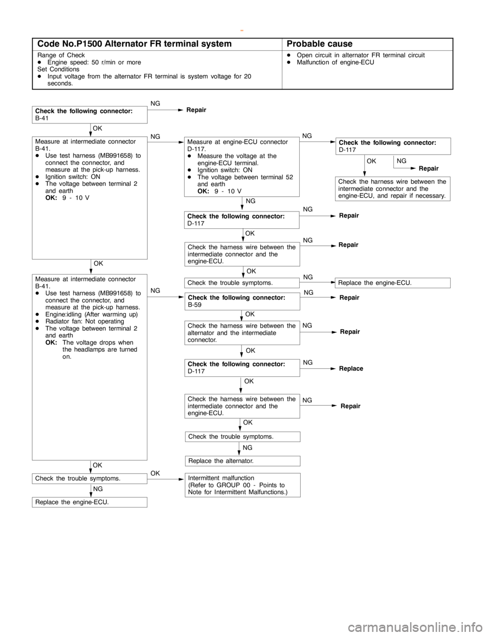
Code No.P1500 Alternator FR terminal systemProbable cause
Range of Check
DEngine speed: 50 r/min or more
Set Conditions
DInput voltage from the alternator FR terminal is system voltage for 20
seconds.DOpen circuit in alternator FR terminal circuit
DMalfunction of engine-ECU
OK
Check the harness wire between the
intermediate connector and the
engine-ECU, and repair if necessary.NG
Repair
NG
Check the following connector:
D-117NG
Repair
Check the following connector:
B-41NG
Repair
OK
Measure at intermediate connector
B-41.
DUse test harness (MB991658) to
connect the connector, and
measure at the pick-up harness.
DEngine:idling (After warming up)
DRadiator fan: Not operating
DThe voltage between terminal 2
and earth
OK:
The voltage drops when
the headlamps are turned
on.NG
Check the following connector:
B-59NG
Repair
OK
Check the trouble symptoms.
NG
Replace the engine-ECU.
OK
Check the harness wire between the
intermediate connector and the
engine-ECU.NG
Repair
OK
Measure at intermediate connector
B-41.
DUse test harness (MB991658) to
connect the connector, and
measure at the pick-up harness.
DIgnition switch: ON
DThe voltage between terminal 2
and earth
OK:
9 - 10 VNGMeasure at engine-ECU connector
D-117.
DMeasure the voltage at the
engine-ECU terminal.
DIgnition switch: ON
DThe voltage between terminal 52
and earth
OK:
9 - 10 VNGCheck the following connector:
D-117
OK
NG
Repair
OK
Check the following connector:
D-117NG
Replace
OK
Check the trouble symptoms.NGReplace the engine-ECU.
OK
Check the harness wire between the
intermediate connector and the
engine-ECU.NG
Repair
NG
Replace the alternator.OK
Check the trouble symptoms.OKIntermittent malfunction
(Refer to GROUP 00 - Points to
Note for Intermittent Malfunctions.)
Check the harness wire between the
alternator and the intermediate
connector.
www.WorkshopManuals.co.uk
Purchased from www.WorkshopManuals.co.uk
Page 308 of 1839

GDI -Troubleshooting
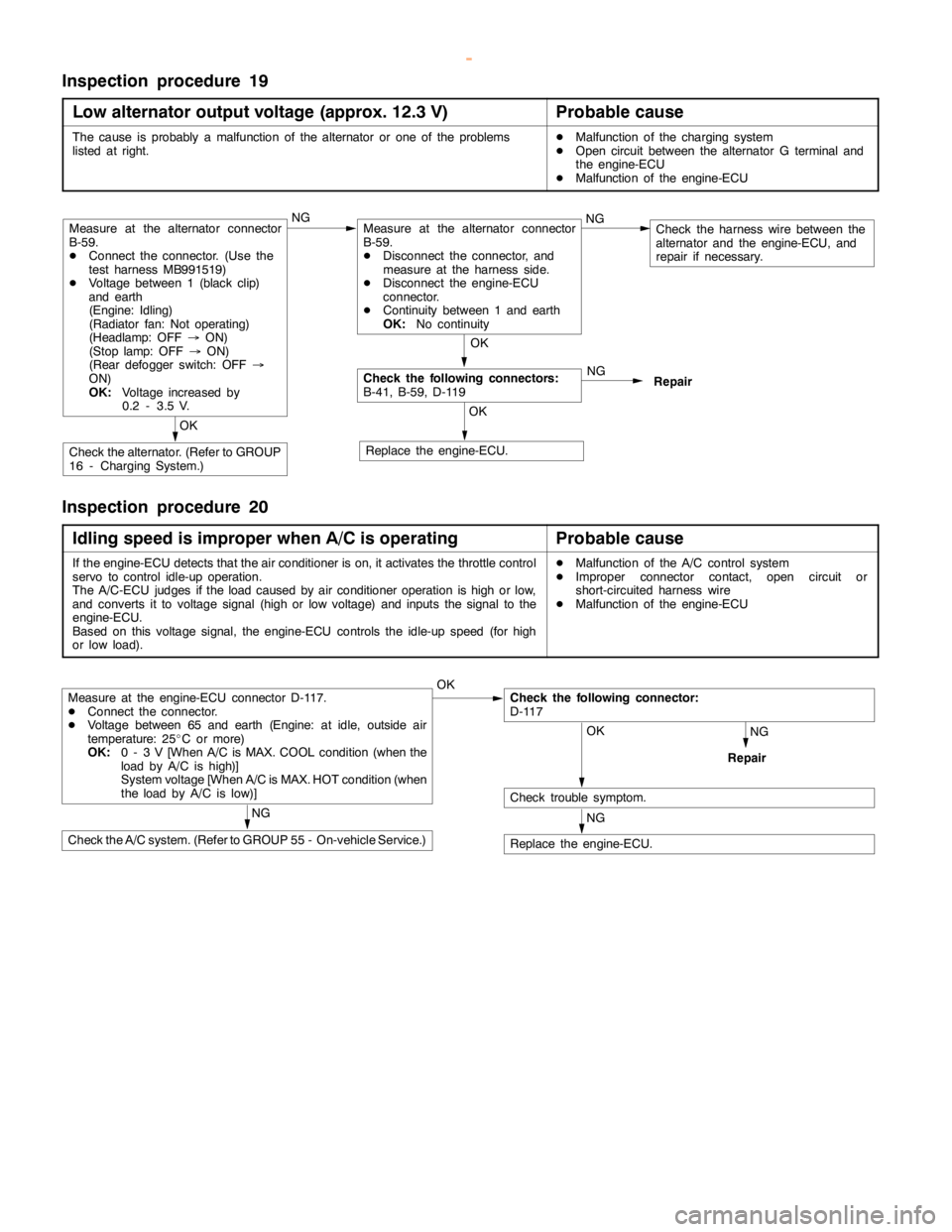
Inspection procedure 19
Low alternator output voltage (approx.12.3 V)
Probable cause
The cause is probably a malfunction of the alternator or one of the problems
listed at right.DMalfunction of the charging system
DOpen circuit between the alternator G terminal and
the engine-ECU
DMalfunction of the engine-ECU
NG
Repair
OK
Replace the engine-ECU.
OK
Check the alternator. (Refer to GROUP
16 - Charging System.)
OK
Check the following connectors:
B-41, B-59, D-119
Measure at the alternator connector
B-59.
DConnect the connector. (Use the
test harness MB991519)
DVoltage between 1 (black clip)
and earth
(Engine: Idling)
(Radiator fan: Not operating)
(Headlamp: OFF®ON)
(Stoplamp: OFF®ON)
(Rear defogger switch: OFF®
ON)
OK:
Voltage increased by
0.2 - 3.5 V.NGMeasure at the alternator connector
B-59.
DDisconnect the connector, and
measure at the harness side.
DDisconnect the engine-ECU
connector.
DContinuity between 1 and earth
OK:
No continuityNGCheck the harness wire between the
alternator and the engine-ECU, and
repair if necessary.
Inspection procedure 20
Idling speed is improper when A/C is operating
Probable cause
If the engine-ECU detects that the air conditioner is on, it activates the throttle control
servo to control idle-up operation.
The A/C-ECU judges if theloadcaused by air conditioner operation ishigh or low,
and converts it to voltage signal (high or low voltage) and inputs the signal to the
engine-ECU.
Based on this voltage signal, the engine-ECU controls the idle-up speed (forhigh
or low load).DMalfunction of the A/C control system
DImproper connector contact,opencircuit or
short-circuited harness wire
DMalfunction of the engine-ECU
NG
Repair
Measure at the engine-ECU connector D-117.
DConnect the connector.
DVoltage between 65 and earth (Engine: at idle, outside air
temperature: 25_C or more)
OK:
0 - 3 V [When A/C is MAX. COOL condition (when the
load by A/C is high)]
System voltage [When A/C is MAX. HOT condition (when
the load by A/C islow)]OKCheck the following connector:
D-117
OK
Check trouble symptom.
NG
Replace the engine-ECU.
NG
Check the A/C system. (Refer to GROUP 55 - On-vehicle Service.)
www.WorkshopManuals.co.uk
Purchased from www.WorkshopManuals.co.uk
Page 327 of 1839

GDI -Troubleshooting
Terminal
No.Normal condition Check requirements (engine condition) Check item
47Power supplyIgnition switch: ONSystem voltage
59
50Camshaft position sensorEngine: Cranking0.4 - 3.0 V
Engine: Idling0.5 - 2.0 V
51Barometric pressure sensorIgnition switch:Altitude: 0 m3.7 - 4.3 V
ON
Altitude: 1,200 m3.2 - 3.8 V
52Alternator FR terminalDEngine: Warm up, and then idling
DRadiator fan: not operating
DHeadlamp: OFF®ON
DStop lamp: OFF®ON
DRear defogger: OFF®ONVoltage decreases
53Oxygen sensor (rear)DTransmission: 2nd gear
DEngine speed: 3,500 r/min or more
DDriving with the throttle valve widely
open0.6 - 1.0 V
54Power steering fluid
pressure switchEngine: Warm
up, and thenSteering wheel
stationarySystem voltage
idling
Steering wheel
turning0-3V
55Injector driver relayIgnition switch: OFF0 - 0.1 V
Ignition switch: ON0.5 - 1.0 V
56Throttle valve control servoIgnition switch: OFF0 - 0.3 V
relay
Ignition switch: ON0.5 - 1.0 V
57Engine control relayIgnition switch: OFF0-3V
Ignition switch: ONSystem voltage
60Back-up power sourceIgnition switch: OFFSystem voltage
61Air flow sensorEngine: Idling2.2 - 3.2 V
Engine: 2,500 r/min
62Intake air temperature
sensorIgnition switch:
ONIntake air temper-
ature: 0_C3.2 - 3.8 V
Intake air temper-
ature: 20_C2.3 - 2.9 V
Intake air temper-
ature: 40_C1.5 - 2.1 V
Intake air temper-
ature: 80_C0.4 - 1.0 V
www.WorkshopManuals.co.uk
Purchased from www.WorkshopManuals.co.uk
Page 367 of 1839

Page 380 of 1839

Page 493 of 1839

DIESEL FUEL <4M4> -General Information13C-2
GENERAL INFORMATION
The electronically-controlled fuel injection system consists of sensors which detect the condition of the
diesel engine, an engine-ECU which controls the system based on signals from these sensors, and actuators
which operate according to control commands from the engine-ECU.
The engine-ECU carries out operations such as fuel injection rate control, fuel injection timing control
and idle up control. In addition, the engine-ECU is equipped with several self-diagnosis functions which
make troubleshooting easier in the event that a problem develops.
FUEL INJECTION RATE CONTROL
The fuel injection completion timing is controlled by means of a solenoid-type spill valve to ensure that
the optimum amount of fuel is supplied to the engine in accordance with gradual changes in the engine
running condition.
Before fuel injection starts, the solenoid-type spill valve is on (energized), so that the valve is closed.
As the plunger turns and rises, fuel is sent out under pressure, and when the fuel flow rate reaches
the target value for fuel injection, the solenoid-type spill valve turns off. When the solenoid-type spill
valve turns off, the fuel under high pressure inside the plunger is leaked out into the pump chamber
and fuel injection is completed.
FUEL INJECTION TIMING CONTROL
The position of the injection pump timer piston is controlled so that fuel injection is carried out at the
optimum timing in accordance with the engine running condition.
The timer piston position is determined by duty control of the timing control solenoid valve which is located
in the line between the high-pressure chamber and the low-pressure chamber of the timer piston.
The fuel injection timing is advanced by increasing the control duty of the timing control solenoid valve.
IDLE SPEED CONTROL
Controlling the fuel injection rate in accordance with the engine running condition maintains the idle speed
at the optimum condition.
SELF-DIAGNOSIS FUNCTION
DWhen an abnormality is detected in any of the sensors or actuators, the engine warning lamp illuminates
to warn the driver.
DWhen an abnormality is detected in any of the sensors or actuators, a diagnosis code number
corresponding to the problem which occurred is output.
DThe RAM data relating to the sensors and actuators which is stored in the engine-ECU can be read
using the MUT-II. In addition, the actuators can be force-driven under certain conditions.
OTHER CONTROL FUNCTIONS
1. Power Supply Control
When the ignition switch is turned to ON, the relay turns on and power is supplied to components
such as the timing control solenoid valve.
2. Intake Air Throttle Control
When the engine is idling after having warmed up, the throttle valve is half opened to restrict the
amount of intake air in order to reduce vibration and noise.
3. A/C Relay Control
Turns the compressor clutch of the A/C ON and OFF
4. Fan motor relay control
The radiator fan and condenser fan operating speeds are controlled in accordance with the engine
coolant temperature and the vehicle speed.
5. Glow Control
Refer to GROUP 16.
6. EGR Control
Refer to GROUP 17.
www.WorkshopManuals.co.uk
Purchased from www.WorkshopManuals.co.uk
Page 678 of 1839

14-1
ENGINE COOLING
CONTENTS
GENERAL INFORMATION 2..................
SERVICE SPECIFICATIONS 2.................
LUBRICANT 2...............................
SEALANT 2..................................
ON-VEHICLE SERVICE 3.....................
Engine Coolant Leak Checking 3................
Radiator Cap Valve Opening Pressure Check
3 .............................................Engine Coolant Replacement 3..................
Concentration Measurement 5...................
COOLING FAN 6.............................
THERMOSTAT 8.............................
WATER PUMP 11............................
WATER HOSE AND WATER PIPE 15........
RADIATOR 20...............................
www.WorkshopManuals.co.uk
Purchased from www.WorkshopManuals.co.uk
Page 679 of 1839

ENGINE COOLING -General Information/
Service Specifications/Lubricant/Sealant14-2
GENERAL INFORMATION
The cooling system is designed to keep every part
of the engine at appropriate temperature in
whatever condition the engine may be operated.
The cooling method is of the water-cooled, pressure
forced circulation type in which the water pump
pressurizes coolant and circulates it throughout the
engine. If the coolant temperature exceeds the
prescribed temperature, the thermostat opens to
circulate the coolant through the radiator as well
so that the heat absorbed by the coolant may be
radiated into the air.The water pump is of the centrifugal type and is
driven by the drive belt from the crankshaft.
The radiator is the corrugated fin, down flow type.
ItemsSpecifications
RadiatorPerformance kJ/h6G7203,023
4D5, 4M4232,326
SERVICE SPECIFICATIONS
ItemsStandard valueLimit
High pressure valve opening pressure of radiator cap kPa74 - 10364
Range of coolant antifreeze concentration of radiator %30 - 60-
ThermostatValve opening temper-6G788±
2.0-
ature of thermostat_
C4D582±
1.5-
4M476.5±
2.0-
Full-opening tempera-6G7100-
ture of thermostat_
C4D595-
4M490-
Valve lift mm6G710 or more-
4D5, 4M48.5 or more-
LUBRICANT
ItemApplicable modelAmount (including
condense tank) L
MITSUBISHI GENUINE COOLANT or equivalentVehicles without rear heater9.0
Vehicles with rear heater10.5
SEALANT
ItemsSpecified sealantRemarks
Cylinder block drain plug3M Nut Locking Part No. 4171 or equivalentDrying sealant
www.WorkshopManuals.co.uk
Purchased from www.WorkshopManuals.co.uk
Page 1165 of 1839

POWER PLANT MOUNT - No.1 Crossmember32-7
No.1 CROSSMEMBER
REMOVAL AND INSTALLATION
Caution
1. Before removing the steering wheel and airbag module assembly, always refer to GROUP 52B
- Service Precautions, Airbag Module and Clock Spring. Also, set the front wheels so that
they are facing straight forward, and remove the ignition key. If you fail to do this, the SRS
clock spring will be damaged, causing the SRS airbag to be inoperative and serious injury.
2. *: Indicates parts which should be initially tightened, and then fully tightened after placing
the vehicle horizontally and loading the full weight of the engine on the vehicle body.
Pre-removal Operation
DUnder Cover Removal
DDrive Shaft Removal
(Refer to GROUP 26.)
DDifferential Carrier and No.2 Crossmember
Assembly Removal (Refer to GROUP 26 -
Freewheel Assembly and Differential Carrier.)
DUpper Arm Removal
(Refer to GROUP 33A.)
DLower Arm Removal
(Refer to GROUP 33A.)
DStabilizer Bar Removal
(Refer to GROUP 33A.)
DEngine Oil Cooler Removal<6G7>
(Refer to GROUP 12.)
DAir Cleaner Removal<4M4>
(Refer to GROUP 15.)
DIntercooler Removal<4M4>
(Refer to GROUP 15.)
DEngine Cover Removal
(Refer to GROUP 11A - Timing Belt.)
DRadiator Removal
(Refer to GROUP 14.)
DPower Steering Fluid Draining
(Refer to GROUP 37A - On - vehicle Service.)Post - installation Operations
DDifferential Carrier and No.2 Crossmember
Assembly Installation (Refer to GROUP 26 -
Freewheel Assembly and Differential Carrier.)
DDrive Shaft Installation
(Refer to GROUP 26.)
DLower Arm Installation
(Refer to GROUP 33A.)
DUpper Arm Installation
(Refer to GROUP 33A.)
DStabilizer Bar Installation
(Refer to GROUP 33A.)
DAir Cleaner Installation<4M4>
(Refer to GROUP 15.)
DIntercooler Installation<4M4>
(Refer to GROUP 15.)
DRadiator Installation
(Refer to GROUP 14.)
DEngine Oil Cooler Installation
(Refer to GROUP 12.)
DPower Steering Fluid Supplying
(Refer to GROUP 37A - On - vehicle Service.)
DPower Steering Fluid Line Bleeding
(Refer to GROUP 37A - On - vehicle Service.)
DPress the dust cover with a finger tocheck whether
the dust cover is cracked or damaged.
DChecking Steering Wheel Position with Wheels
StraightAhead
DFront Wheel AlignmentCheck and Adjustment
(Refer to GROUP 37A - On - vehicle Service.)
DUnder Cover Installation
DEngine Cover Installation
(Refer to GROUP 11A - Timing Belt.)
www.WorkshopManuals.co.uk
Purchased from www.WorkshopManuals.co.uk