fuse MITSUBISHI OUTLANDER 2016 3.G Owners Manual
[x] Cancel search | Manufacturer: MITSUBISHI, Model Year: 2016, Model line: OUTLANDER, Model: MITSUBISHI OUTLANDER 2016 3.GPages: 464, PDF Size: 60.77 MB
Page 2 of 464
Instruments and controls 1-1
1
Overview
N00100202658
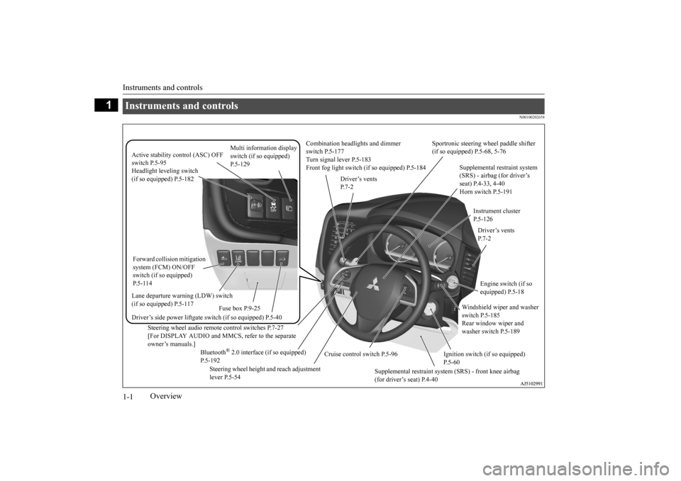
Instruments and controls
Combination headlights and dimmer switch P.5-177 Turn signal lever P.5-183 Front fog light switch (if so equipped) P.5-184
Steering wheel audio remote control switches P.7-27 [For DISPLAY AUDIO and MMCS, refer to the separateowner’s manuals.]
Active stability control (ASC) OFF switch P.5-95
Supplemental restraint system (SRS) - airbag (for driver’s seat) P.4-33, 4-40 Horn switch P.5-191
Instrument cluster P.5-126
Windshield wiper and washer switch P.5-185 Rear window wiper and washer switch P.5-189
Cruise control switch P.5-96
Steering wheel height and reach adjustment lever P.5-54
Engine switch (if so equipped) P.5-18
Bluetooth
® 2.0 interface (if so equipped)
P.5-192
Driver’s vents P. 7 - 2
Sportronic steering wheel paddle shifter (if so equipped) P.5-68, 5-76
Driver’s vents P. 7 - 2
Multi information display switch (if so equipped) P.5-129
Headlight leveling switch (if so equipped) P.5-182 Driver’s side power liftgate switch (if so equipped) P.5-40
Fuse box P.9-25
Lane departure warning (LDW) switch (if so equipped) P.5-117 Forward collision mitigation system (FCM) ON/OFF switch (if so equipped) P. 5 - 1 1 4
Supplemental restraint system (SRS) - front knee airbag (for driver’s seat) P.4-40
Ignition switch (if so equipped) P.5-60
BK0223400US.book 1 ページ 2015年2月13日 金曜日 午後12時15分
Page 24 of 464
Genuine Mitsubishi Motors parts 3-6 General information
3
Modification of any onboard com- puter/control module, including repro-gramming, or replacing/adding chips to any onboard computer/control module
Review the Warranty and Maintenance Man- ual for further details
regarding warranty cov-
erage.
N00301701219
The installation of accessories, optional parts, etc., should only be performed within the limits prescribed by law, and inaccordance with the guidelines and warn- ings contained within the documents accompanying this vehicle.Only Mitsubishi Moto
rs approved acces-
sories should be fitt
ed to your vehicle.
Improper installation of
electrical parts
could cause a fire. Refer to the “Modifica- tion/alterations to the electrical or fuel systems” section with
in this owner’s man-
ual.
Using a cellular phone or radio set inside the vehicle without an
external antenna
may cause electrical system interference, which could lead to unsafe vehicle opera- tion. Tires and wheels whic
h do not meet spec-
ifications must not be used. Refer to the “Specifications” section forinformation regard
ing wheel and tire
sizes.
Due to the large number of accessory and replacement parts provided by different man- ufacturers in the market, it is not always pos-sible for an authorized Mitsubishi Motors dealer to check whether the attachment or installation of a non-Mi
tsubishi Motors genu-
ine parts affects the driving safety of your Mitsubishi-vehicle.
N00301800141
Mitsubishi Motors manu
factures high quality
vehicles with an emphasis on safety. It is important to consult an
authorized Mitsubishi
Motors dealer before
installation of any
accessory which may in
volve modification of
the electrical or fuel systems.
N00301400219
Mitsubishi Motors Genuine Parts aredesigned and manufactured to meet high stan-dards of performance, and are recommended for all of your maintenance needs. Also avail-
Installation of accessories
CAUTION Before any electrical or electronic accesso- ries are installed, cons
ult an authorized Mit-
subishi Motors dealer.
WA R N I N G While driving, do not use a cellular phone in a way that hinder
s safe driving. Any-
thing, including cell
ular phone usage, that
distracts you from the safe operation of your vehicle incr
eases your risk of an acci-
dent.Refer to and follow al
l state and local laws
in your area regardi
ng cellular phone
usage while driving.
Important point!
Modification/alterations to the electrical or fuel systems
CAUTION Please consult an authorized Mitsubishi Motors dealer concer
ning any such acces-
sory fitment or modification.If the wires interfere
with the vehicle body or
improper installation me
thods are used (pro-
tective fuses not included, etc.), electronicdevices may be adversel
y affected, resulting
in a fire, vehicle dama
ge, or other accident.
Genuine Mitsubishi Motors parts
BK0223400US.book 6 ページ 2015年2月13日 金曜日 午後12時15分
Page 116 of 464
Power liftgate (if so equipped) 5-40 Features and controls
5
N00576100038
The power liftgate ca
n be opened automati-
cally when all of the
following conditions are
met.
The power liftgate is completely closed. The power liftgate is unlocked.
The power liftgate can
be closed automati-
cally when all of the
following conditions are
met.
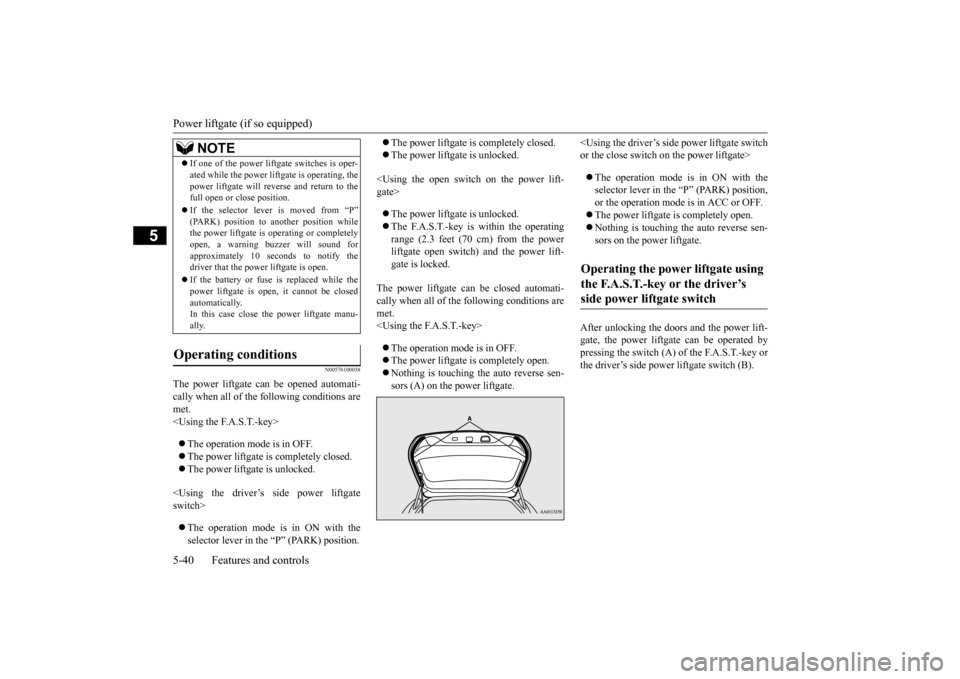
After unlocking the doors and the power lift- gate, the power liftgate can be operated by pressing the switch (A) of the F.A.S.T.-key or the driver’s side power liftgate switch (B).
If one of the power lift
gate switches is oper-
ated while the power lift
gate is operating, the
power liftgate will reve
rse and return to the
full open or close position. If the selector lever is moved from “P” (PARK) position to another position while the power liftgate is operating or completely open, a warning buzzer will sound forapproximately 10 seconds to notify the driver that the power liftgate is open. If the battery or fuse is replaced while the power liftgate is open,
it cannot be closed
automatically.In this case close the power liftgate manu- ally.
Operating conditions
NOTE
Operating the power liftgate using the F.A.S.T.-key or the driver’s side power liftgate switch
BK0223400US.book 40 ページ 2015年2月13日 金曜日 午後12時15分
Page 127 of 464
Sunroof (if so equipped)
Features and controls 5-51
5
N00528801129
If a hand or head is trapped, for safety the door window is automati
cally lowered a little.
After the obstruction is removed, pull up the switch again to close the door window.
N00551400014
Wind buffeting can be described as the per-ception of pressure on the ears or a boomingor rumbling sound. Your vehicle may exhibit wind buffeting when driving with one or both rear door windows down or partially opened.This is a normal occurrence that can be mini- mized. If the buffeting
occurs with the rear
door windows open, open the front door win- dows as well as the rear door windows to minimize the condition.
N00511001682
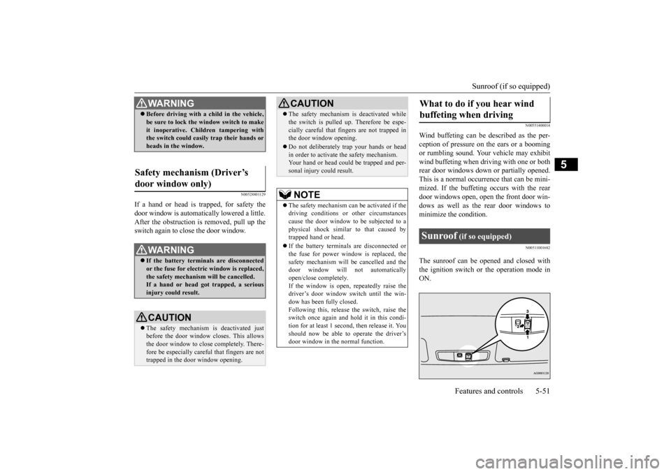
The sunroof can be ope
ned and closed with
the ignition switch or the operation mode in ON.
WA R N I N G Before driving with a child in the vehicle, be sure to lock the window switch to makeit inoperative. Children tampering withthe switch could easily trap their hands or heads in the window.
Safety mechanism (Driver’s door window only)
WA R N I N G If the battery terminals are disconnected or the fuse for electric window is replaced, the safety mechanism will be cancelled.If a hand or head got
trapped, a serious
injury could result.CAUTION The safety mechanism is deactivated just before the door window closes. This allows the door window to close completely. There-fore be especially care
ful that fingers are not
trapped in the door window opening.
The safety mechanism is deactivated while the switch is pulled up.
Therefore be espe-
cially careful that fi
ngers are not trapped in
the door window opening. Do not deliberately trap your hands or head in order to activate the safety mechanism. Your hand or head coul
d be trapped and per-
sonal injury could result.NOTE
The safety mechanism can be activated if the driving conditions or
other circumstances
cause the door window to be subjected to a physical shock similar to that caused by trapped hand or head. If the battery terminals are disconnected or the fuse for power window is replaced, thesafety mechanism will
be cancelled and the
door window will not automatically open/close completely.If the window is open,
repeatedly raise the
driver’s door window switch until the win- dow has been fully closed.Following this, release the switch, raise theswitch once again and hold it in this condi- tion for at least 1 second, then release it. You should now be able to operate the driver’sdoor window in the normal function.CAUTION
What to do if you hear wind buffeting when driving Sunroof
(if so equipped)
BK0223400US.book 51 ページ 2015年2月13日 金曜日 午後12時15分
Page 145 of 464
Automatic transaxle (if so equipped)
Features and controls 5-69
5
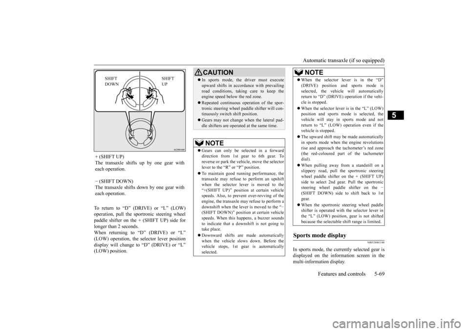
To return to “D” (DRIVE) or “L” (LOW) operation, pull the sportronic steering wheelpaddle shifter on the + (SHIFT UP) side for longer than 2 seconds. When returning to “D” (DRIVE) or “L”(LOW) operation, the selector lever position display will change to “D” (DRIVE) or “L” (LOW) position.
N00538801180
In sports mode, the curre
ntly selected gear is
displayed on the information screen in the multi-information display.
+ (SHIFT UP) The transaxle shifts up by one gear with each operation. − (SHIFT DOWN) The transaxle shifts down by one gear witheach operation.
SHIFT UP
SHIFT DOWN
CAUTION In sports mode, the driver must execute upward shifts in accordance with prevailingroad conditions, taking care to keep theengine speed below the red zone. Repeated continuous ope
ration of the spor-
tronic steering wheel pa
ddle shifter will con-
tinuously switch shift position. Gears may not change when the lateral pad- dle shifters are operated at the same time. NOTE
Gears can only be selected in a forward direction from 1st gear to 6th gear. Toreverse or park the vehi
cle, move the selector
lever to the “R” or “P” position. To maintain good running performance, the transaxle may refuse to perform an upshift when the selector lever is moved to the“+(SHIFT UP)” positi
on at certain vehicle
speeds. Also, to prevent over-revving of the engine, the transaxle may refuse to perform adownshift when the lever is moved to the “
−
(SHIFT DOWN)” position
at certain vehicle
speeds. When this happens, a buzzer soundsto indicate that a dow
nshift is not going to
take place. Downward shifts are made automatically when the vehicle slows down. Before the vehicle stops, 1st ge
ar is automatically
selected.
When the selector lever is in the “D” (DRIVE) position and sports mode isselected, the vehicle will automaticallyreturn to “D” (DRIVE)
operation if the vehi-
cle is stopped. When the selector lever is in the “L” (LOW) position and sports mode is selected, the vehicle will stay in
sports mode and not
return to “L” (LOW) operation even if the vehicle is stopped. The upward shift may be
made automatically
in sports mode when the engine revolutions rise and approach the tachometer’s red zone(the red-coloured part of the tachometer dial). When pulling away from a standstill on a slippery road, pull the sportronic steering wheel paddle shifter on the + (SHIFT UP)side to select 2nd gear
. Pull the sportronic
steering wheel paddle shifter on the
−
(SHIFT DOWN) side to shift back to 1stgear. When the sportronic steering wheel paddle shifter is operated with the selector lever in the “L” (LOW) position, gear is not shifted because the selectable shift range is limited.
Sports mode display
NOTE
BK0223400US.book 69 ページ 2015年2月13日 金曜日 午後12時15分
Page 153 of 464
Continuously variable transmission (CVT) (if so equipped)
Features and controls 5-77
5
When returning to “D” (DRIVE) operation, the selector lever posi
tion display will change
to “D” (DRIVE) position.
N00560901067
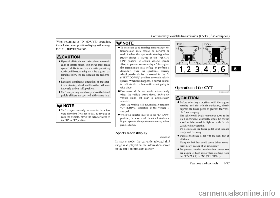
In sports mode, the currently selected shift range is displayed on the information screen in the multi-information display.
N00560801053
CAUTION Upward shifts do not
take place automati-
cally in sports mode. The driver must makeupward shifts in accordance with prevailing road conditions, making sure the engine rpm remains below the red zone on the tachome-ter. Repeated continuous ope
ration of the spor-
tronic steering wheel pa
ddle shifter will con-
tinuously switch shift position. Shift ranges may not cha
nge when the lateral
paddle shifters are opera
ted at the same time.
NOTE
Shift ranges can only be
selected in a for-
ward direction from 1st to 6th. To reverse orpark the vehicle, move
the selector lever to
the “R” or “P” position.
To maintain good running performance, the transmission may refuse to perform anupshift when the sportronic steering wheelpaddle shifter is moved to the “+(SHIFT UP)” position at cert
ain vehicle speeds.
Also, to prevent over-revving of the engine,the transmission may refuse to perform a downshift when the
sportronic steering
wheel paddle shifter is moved to the “
−
(SHIFT DOWN)” position
at certain vehicle
speeds. When this happens, a buzzer sounds to indicate that a dow
nshift is not going to
take place. Downward shifts are made automatically when the vehicle slows down. Before the vehicle stops, 1st ge
ar is automatically
selected.Also, the vehicle will automatically return to “D” (DRIVE) operation
if the vehicle is
stopped. When the selector lever is in the “L” (LOW) position, the sport mode
is not selected even
if you operate the spor
tronic steering wheel
paddle shifter.
Sports mode display
NOTE
Operation of the CVT
CAUTION Before selecting a pos
ition with the engine
running and the vehicl
e stationary, firmly
depress the brake pedal to prevent the vehi-cle from creeping. The vehicle will begin to move as soon as the CVT is engaged, especi
ally when the engine
speed or idle speed is
high, or with the air
conditioning operating. Do not release the brak
e pedal until you are
ready to drive away. Depress the brake pedal
with the right foot at
all times. Using the left foot could cause driver move- ment delay in case of an emergency. To prevent sudden acce
leration, never run
the engine at high rpms when shifting fromthe “P” (PARK) or “N” (NEUTRAL).Type 1 Type 2
BK0223400US.book 77 ページ 2015年2月13日 金曜日 午後12時15分
Page 259 of 464
Turn signal lever
Features and controls 5-183
5
N00522601529
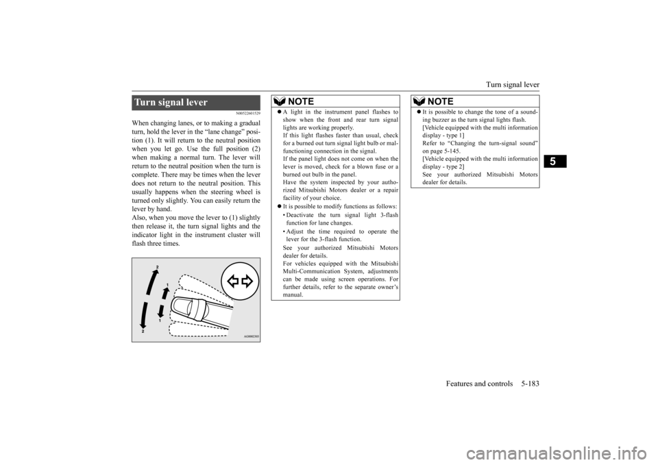
When changing lanes, or to making a gradual turn, hold the lever in the “lane change” posi- tion (1). It will return to the neutral positionwhen you let go. Use the full position (2) when making a normal turn. The lever will return to the neutral position when the turn iscomplete. There may be times when the lever does not return to th
e neutral position. This
usually happens when
the steering wheel is
turned only slightly. You
can easily return the
lever by hand.Also, when you move the lever to (1) slightly then release it, the turn signal lights and the indicator light in the instrument cluster willflash three times.Turn signal lever
NOTE
A light in the instrument panel flashes to show when the front and rear turn signallights are working properly.If this light flashes fast
er than usual, check
for a burned out turn signal light bulb or mal- functioning connecti
on in the signal.
If the panel light does not come on when the lever is moved, check
for a blown fuse or a
burned out bulb in the panel.Have the system inspected by your autho- rized Mitsubishi Motors
dealer or a repair
facility of your choice. It is possible to modify functions as follows: • Deactivate the turn signal light 3-flash function for lane changes. • Adjust the time required to operate the lever for the 3-flash function. See your authorized Mitsubishi Motors dealer for details. For vehicles equipped
with the Mitsubishi
Multi-Communication System, adjustments can be made using sc
reen operations. For
further details, refer to the separate owner’smanual.
It is possible to change the tone of a sound- ing buzzer as the turn signal lights flash.[Vehicle equipped with the multi informationdisplay - type 1] Refer to “Changing the turn-signal sound” on page 5-145.[Vehicle equipped with the multi information display - type 2] See your authorized Mitsubishi Motorsdealer for details.NOTE
BK0223400US.book 183 ページ 2015年2月13日 金曜日 午後12時15分
Page 270 of 464

Bluetooth® 2.0 interface (if so equipped) 5-194 Features and controls
5
Press this button to decrease the volume. Press this button to ch
ange to voice recog-
nition mode.While the system is in voice recognition mode, “Listening” will appear on the audio display. If you press the button briefly while in voice recogniti
on mode, it will interrupt
prompting and allow voice commandinput. Pressing the button lo
nger will deactivate
the voice recognition mode. Pressing this button briefly during a call will enable voice
recognition and allow
voice command input.
Press this button when an incoming call is received to answer the telephone. When another call is received during a call, press this button to put the first caller on hold and talk to the new caller. • In such circumstance
s, you can press the
button briefly to switch between callers. You will switch to the first caller and theother caller will
be put on hold.
• To establish a three-way call in such situ- ations, press the SPEECH button to entervoice recognition mode and then say “Join calls.”
Press this button when an incoming call is received to refuse the call. Press this button during a call to end the current call.When another call is on hold, you will switch to that call.
If this button is presse
d in the voice recog-
nition mode, the voi
ce recognition mode
will be deactivated.
Your voice will be
recognized by a micro-
phone in the overhead console, allowing youto make hands-free ca
lls with voice com-
mands.
Volume down button
SPEECH button
NOTE
On vehicles equipped
with the Mitsubishi
Multi-Communication System, pressing the SPEECH button will ac
tivate the voice rec-
ognition mode (a beep will sound when suc- cessfully activated)
. To use the voice
recognition of the Bluetooth
® 2.0 interface,
press the PICK-UP button.
PICK-UP button
NOTE
When not receiving in
coming calls, pressing
the PICK-UP button on
vehicles equipped
with the Mitsubishi Multi-Communication System, will activate
the voice recognition of
the Bluetooth
® 2.0 interface.
HANG-UP button
NOTE
When you press the SPEECH button (except for vehicles with Mitsubishi Multi-Commu-nication System) or
PICK-UP button (for
vehicles with Mitsubishi Multi-Communica- tion System) to enter
voice recognition mode
with a cellular phone paired to the system, current information on the cellular phone, such as “remaining ba
ttery life,” “signal
strength” or “roaming,”
will be displayed on
the audio display.
*
* : Some cellular phones will not send this information to the Bluetooth
® 2.0 interface.
Call waiting and three-
way calls can be used
by the Bluetooth
® 2.0 interface, only if it is
possible to use those services with your cel- lular phone.
Microphone
BK0223400US.book 194 ページ 2015年2月13日 金曜日 午後12時15分
Page 399 of 464
9
Vehicle care and maintenanceService precautions ..........................................................................9-2 Catalytic converter ...........................................................................9-2 Engine hood .........
...........
...........
............
...........
.........
........
.........
.....9-3
View of the engine compartment .....................................................9-5 Engine oil and oil filter ....................................................................9-6 Engine coolant .................................................................................9-8Air cleaner filter ...............................................................................9-9 Automatic transaxle fluid (if so equipped) ..................................... 9-11 Continuously variable transmission
(CVT) fluid (if so equipped) . 9-11
Transfer oil (All-wheel drive models) ...........................................9-12 Rear axle oil (All-wheel drive models) .........................................9-12 Washer fluid ...................................................................................9-12Brake fluid .....................................................................................9-12 Battery ............................................................................................9-13 Tires ...............................................................................................9-15Brake pedal free play .....................................................................9-21 Parking brake .................................................................................9-22 Wiper blades ..................................................................................9-22Emission-control system maintenance ..........................................9-22 General maintenance .....................................................................9-23 For cold and snowy weather ..........................................................9-25Fusible links ...................................................................................9-25 Fuses ..............................................................................................9-25 Replacement of light bulbs ............................................................9-29Vehicle care precautions ................................................................9-38 Cleaning the inside of your vehicle .......
...........
...........
...........
.......9-38
Cleaning the outside of your vehicle .....
...........
...........
...........
.......9-39
BK0223400US.book 1 ページ 2015年2月13日 金曜日 午後12時15分
Page 423 of 464
For cold and snowy weather
Vehicle care and maintenance 9-25
9
N00942501124
The hood lock release mechanism and hood safety catch should be
checked, cleaned, and
oiled when needed for easy movement and to prevent rust and wear. Use Multipurpose Grease NLGI Grade 2 sp
aringly for all sliding
parts of the hood latc
h and release lever.
Work the grease into the hood lock mecha- nism until all the mo
vable surfaces are cov-
ered. Also, put a light coat of the same grease onthe safety catch wherever moving parts touch.
N00942600102
The ventilation slots in front of the wind-shield should be brus
hed clear after a heavy
snowfall so that the operation of the heating and ventilation systems
will not be impaired.
To prevent freezing of the weatherstripping on the doors, engine hood, etc., they should be treated with silicone grease. It is a good idea to carry a shovel or a short- handled spade in the vehicle during the win-ter so that you can clear away snow if you get stranded. A small hand-brush for sweeping snow off the vehicle a
nd a plastic scraper for
the windshield, side an
d rear window are also
useful.
N00942700291
The fusible links will melt to prevent a fire ifa large current attempts
to flow through cer-
tain electrical systems.In case of a melted fusible link, see your authorized Mitsubishi Motors dealer or a repair facility of your
choice for inspection
and replacement. For the fusible links, pl
ease refer to “Fuse
load capacities” on page 9-26.
N00942801912
To prevent damage to the electrical systemfrom short-circuiting
or overloading, each
individual circuit is e
quipped with a fuse. The
fuse blocks are located in the passenger com- partment and in the engine compartment. The fuse blocks in the passenger compart- ment are located behind the fuse lid in frontof the driver’s seat at the position shown in the illustration. Pull the fuse lid to remove it.
Hood lock release mechanism and safety catch For cold and snowy weather Ventilation slots
Weatherstripping Additional equipment (For regions where snow is encoun- tered) Fusible links
WA R N I N G Fusible links must not be replaced by any other device. Failing to fit the correct fus-ible link may result in fire in the vehicle,property destruction and serious or fatal injuries at any time.
Fuses Fuse block location Passenger compartment
BK0223400US.book 25 ページ 2015年2月13日 金曜日 午後12時15分