stop start MITSUBISHI OUTLANDER 2017 3.G User Guide
[x] Cancel search | Manufacturer: MITSUBISHI, Model Year: 2017, Model line: OUTLANDER, Model: MITSUBISHI OUTLANDER 2017 3.GPages: 521, PDF Size: 14.91 MB
Page 146 of 521
Steering wheel lock (if so equipped)
Features and controls 5-65
5
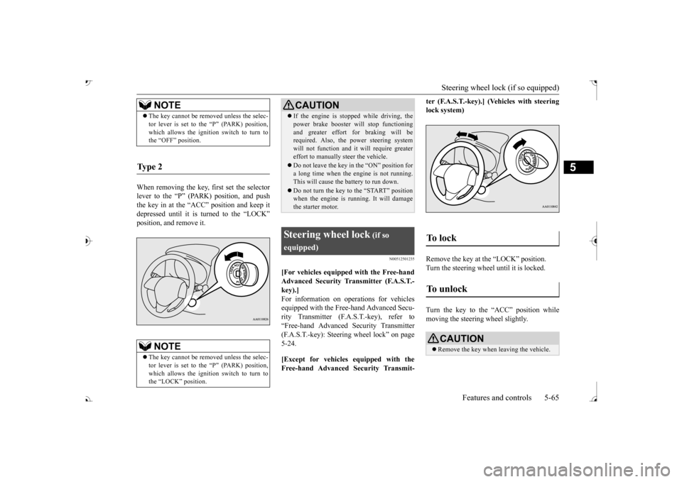
When removing the key, first set the selector lever to the “P” (PARK) position, and push the key in at the “ACC” position and keep it depressed until it is turned to the “LOCK”position, and remove it.
N00512501235
[For vehicles equipped with the Free-handAdvanced Security Transmitter (F.A.S.T.- key).] For information on operations for vehiclesequipped with the Free-hand Advanced Secu- rity Transmitter (F.A.S.T.-key), refer to “Free-hand Advanced Se
curity Transmitter
(F.A.S.T.-key): Steering wheel lock” on page 5-24. [Except for vehicles equipped with the Free-hand Advanced Security Transmit-
ter (F.A.S.T.-key).] (Vehicles with steering lock system) Remove the key at the “LOCK” position. Turn the steering wheel until it is locked. Turn the key to the “ACC” position while moving the steeri
ng wheel slightly.
NOTE
The key cannot be rem
oved unless the selec-
tor lever is set to the “P” (PARK) position,which allows the ignition switch to turn tothe “OFF” position.
Ty p e 2
NOTE
The key cannot be rem
oved unless the selec-
tor lever is set to the “P” (PARK) position,which allows the ignition switch to turn to the “LOCK” position.
CAUTION If the engine is stoppe
d while driving, the
power brake booster will stop functioningand greater effort for braking will berequired. Also, the power steering system will not function and it
will require greater
effort to manually steer the vehicle. Do not leave the key in
the “ON” position for
a long time when the engine is not running.This will cause the battery to run down. Do not turn the key to the “START” position when the engine is ru
nning. It will damage
the starter motor.
Steering wheel lock
(if so
equipped)
To unlock
CAUTION Remove the key when leaving the vehicle.
BK0239700US.book 65 ページ 2016年6月16日 木曜日 午前10時58分
Page 152 of 521
Automatic transaxle (if so equipped)
Features and controls 5-71
5
When the warning display or the warn- ing display appears on
the information screen
in the multi-information display while you are driving, there could be a malfunction in the automatic transaxle.
N00514201425
This position locks the transaxle to prevent the vehicle from moving.
The engine can be
started in the “P” (PARK) position. Move the lever to this position only after the vehicle has come to a complete stop. At this position, the
transaxle is disengaged.
It is the same as th
e neutral position on a
manual transaxle and should be used when the vehicle is not moving for an extended length of time during driving, such as in atraffic jam.
CAUTION If a malfunction occurs in the automatic transaxle while driving, the warning dis- play or the warni
ng display will appear
on the information screen in the multi-infor- mation display. In this case, immediat
ely park your vehicle
in a safe place and fo
llow these procedures:
When warning display is showing The automatic transaxle fluid is overheating. Stop your vehicle in a
safe place, put the
selector lever in the
“P” position, and open
the engine hood with the engine running to allow the engine to c
ool down. After a while,
confirm that the warning display is no longer showing. It is safe to continue driving if the display is no longer showing. If thewarning display rema
ins or flashes fre-
quently, have your vehicle inspected by an authorized Mitsubishi
Motors dealer or a
repair facility
of your choice.
When warning display is showing It may be that there is something unusual happening in the automa
tic transaxle, caus-
ing a safety device to
activate. Have your
vehicle inspected by an
authorized Mitsubi-
shi Motors dealer or a
repair facility of your
choice immediately.
Selector lever positions
“P” PARK
“R” REVERSE
CAUTION Never shift into the “P” (PARK) or “R” motion. If the lever is shifted into the “P”the vehicle is in moti
on, the transaxle may be
damaged.
“N” NEUTRAL
BK0239700US.book 71 ページ 2016年6月16日 木曜日 午前10時58分
Page 158 of 521
Continuously variable transmission (CVT) (if so equipped)
Features and controls 5-77
5
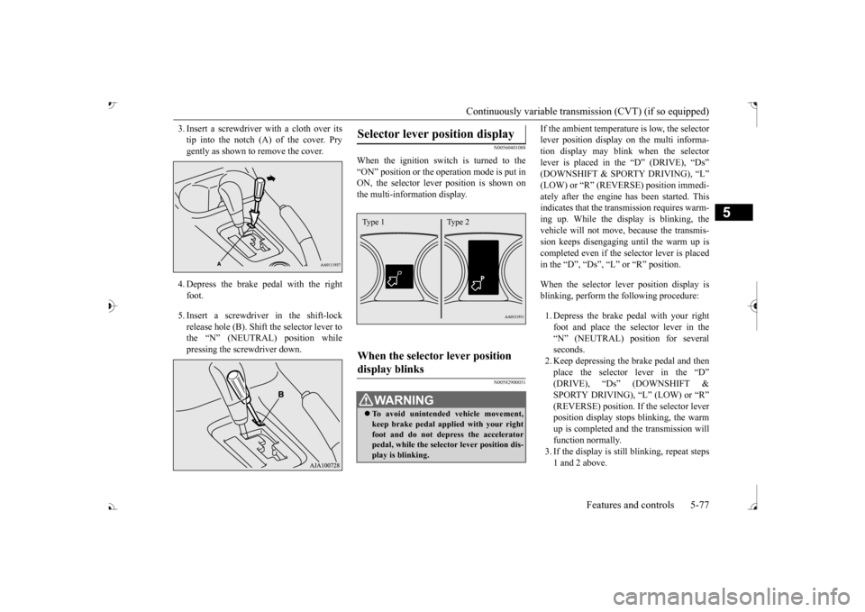
3. Insert a screwdrive
r with a cloth over its
tip into the notch (A) of the cover. Prygently as shown to remove the cover. 4. Depress the brake pe
dal with the right
foot. 5. Insert a screwdriver in the shift-lock release hole (B). Shift the selector lever tothe “N” (NEUTRAL) position while pressing the screwdriver down.
N00560401088
When the ignition switch is turned to the“ON” position or the ope
ration mode is put in
ON, the selector leve
r position is shown on
the multi-information display.
N00582900031
If the ambient temperature is low, the selectorlever position display on the multi informa-tion display may blink when the selector lever is placed in the “D” (DRIVE), “Ds” ately after the engine has been started. This indicates that the tran
smission requires warm-
ing up. While the display is blinking, the vehicle will not move,
because the transmis-
sion keeps disengaging until the warm up is completed even if the selector lever is placed in the “D”, “Ds”, “L” or “R” position. When the selector le
ver position display is
blinking, perform th
e following procedure:
1. Depress the brake pedal with your right foot and place the se
lector lever in the
“N” (NEUTRAL) position for severalseconds. 2. Keep depressing the brake pedal and then place the selector lever in the “D” SPORTY DRIVING), “L” (LOW) or “R” (REVERSE) position. If the selector leverposition display stops
blinking, the warm
up is completed and the transmission will function normally.3. If the display is still
blinking, repeat steps
1 and 2 above.
Selector lever position display
When the selector lever position display blinks
WA R N I N G To avoid unintended
vehicle movement,
keep brake pedal applied with your right foot and do not depress the accelerator pedal, while the selector lever position dis-play is blinking.Type 1 Type 2
BK0239700US.book 77 ページ 2016年6月16日 木曜日 午前10時58分
Page 160 of 521
Continuously variable transmission (CVT) (if so equipped)
Features and controls 5-79
5
N00560601107
This position locks the transmission to pre- vent the vehicle from m
oving. The engine can
be started in the “P” (PARK) position. Move the lever to this position only after the vehicle has come to a complete stop.
At this position, the transmission is disen- gaged. It is the same
as the neutral position on
a manual transaxle and should be used whenthe vehicle is not m
oving for an extended
length of time during driving, such as in a traffic jam.
This position is used fo
r most city and high-
way driving. The transmission will automati- cally and continuously ch
ange its gear ratio
depending on road and driving conditions. Use when engine braking is needed, or for high-power sport drive.
After a while, confirm that the warning display is no longer show
ing. It is safe to
continue driving if the display is no longer showing. If the warn
ing display remains or
flashes frequently,
have your vehicle
inspected by an authorized Mitsubishi Motors dealer or a repair facility of your choice. [When warning di
splay is showing]
It may be that ther
e is something unusual
happening in the CVT, causing a safety device to activate
. Have your vehicle
inspected by an authorized MitsubishiMotors dealer or a repair facility of your choice immediately.
Selector lever positions
“P” PARK
“R” REVERSE
CAUTION
CAUTION Never shift into the “P” (PARK) or “R”motion. If the lever is shifted into the “P” the vehicle is in motion, the transmission may be damaged.
“N” NEUTRAL
WA R N I N G Never move the selector lever to the “N” you could accidentally slip it into the “P” damaging the transmission. To prevent the vehicle from rolling when stopped on a slope,
the engine should be
started in the “P” (PARK) position, not in “N” (NEUTRAL) position.
To prevent rolling, always keep your foot on the brake pedal when the vehicle is in“N” (NEUTRAL) positi
on, or when shift-
ing into or out of
Page 165 of 521
Electronically controlled 4W
D system (if so equipped)
5-84 Features and controls
5
N00549401030
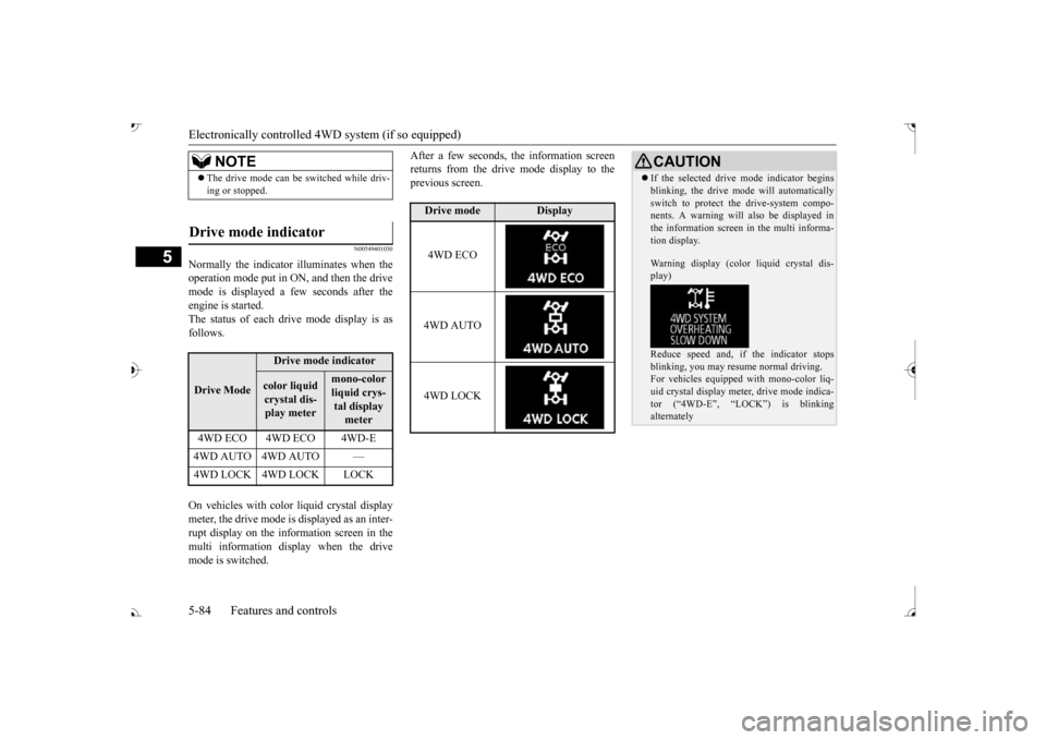
Normally the indicator illuminates when the operation mode put in ON, and then the drivemode is displayed a few seconds after the engine is started. The status of each drive mode display is asfollows. On vehicles with color liquid crystal display meter, the drive mode is displayed as an inter-rupt display on the information screen in the multi information display when the drive mode is switched.
After a few seconds, the information screen returns from the drive mode display to theprevious screen.
NOTE
The drive mode can be
switched while driv-
ing or stopped.
Drive mode indicator
Drive Mode
Drive mode indicatorcolor liquid crystal dis-play meter
mono-color liquid crys- tal display meter
4WD ECO 4WD ECO 4WD-E 4WD AUTO 4WD AUTO —
Drive mode
Display
4WD ECO 4WD AUTO 4WD LOCK
CAUTION If the selected drive mode indicator begins blinking, the drive m
ode will automatically
switch to protect the drive-system compo-nents. A warning will
also be displayed in
the information screen in the multi informa- tion display. Warning display (color liquid crystal dis- play) Reduce speed and, if the indicator stops blinking, you may resume normal driving. For vehicles equipped
with mono-color liq-
uid crystal display mete
r, drive mode indica-
tor (“4WD-E”, “LOC
K”) is blinking
alternately
BK0239700US.book 84 ページ 2016年6月16日 木曜日 午前10時58分
Page 170 of 521
4-wheel drive operation
Features and controls 5-89
5
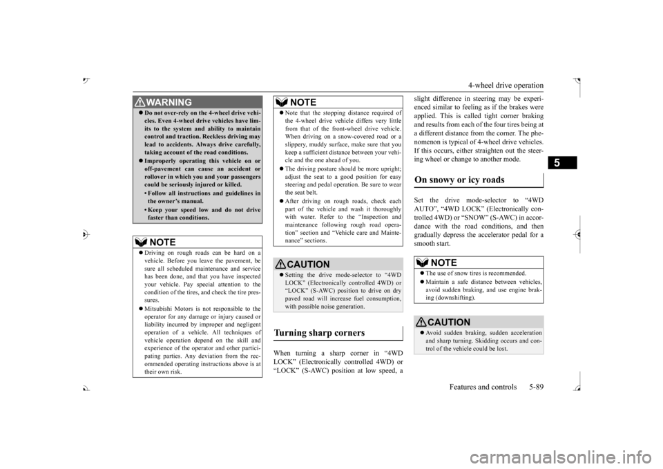
When turning a sharp corner in “4WD LOCK” (Electronically
controlled 4WD) or
“LOCK” (S-AWC) position at low speed, a
slight difference in
steering may be experi-
enced similar to feeling as if the brakes wereapplied. This is called tight corner braking and results from each of the four tires being at a different distance from the corner. The phe-nomenon is typical of 4-wheel drive vehicles. If this occurs, either straighten out the steer- ing wheel or change to another mode. Set the drive mode-selector to “4WD AUTO”, “4WD LOCK” (Electronically con- trolled 4WD) or “SNOW” (S-AWC) in accor- dance with the road conditions, and thengradually depress the ac
celerator pedal for a
smooth start.
WA R N I N G Do not over-rely on th
e 4-wheel drive vehi-
cles. Even 4-wheel drive vehicles have lim-its to the system and ability to maintaincontrol and traction.
Reckless driving may
lead to accidents. Always drive carefully, taking account of the road conditions. Improperly operating
this vehicle on or
off-pavement can cause an accident orrollover in which you
and your passengers
could be seriously
injured or killed.
• Follow all instructions and guidelines in the owner’s manual.• Keep your speed low and do not drivefaster than conditions.NOTE
Driving on rough roads can be hard on a vehicle. Before you le
ave the pavement, be
sure all scheduled ma
intenance and service
has been done, and that
you have inspected
your vehicle. Pay spec
ial attention to the
condition of the ti
res, and check the tire pres-
sures. Mitsubishi Motors is not responsible to the operator for any damage or injury caused or liability incurred by improper and negligent operation of a vehicl
e. All techniques of
vehicle operation depend on the skill and experience of the opera
tor and other partici-
pating parties. Any de
viation from the rec-
ommended operating instru
ctions above is at
their own risk.
Note that the stopping distance required of the 4-wheel drive vehicl
e differs very little
from that of the front-wheel drive vehicle.When driving on a snow-covered road or a slippery, muddy surface,
make sure that you
keep a sufficient dist
ance between your vehi-
cle and the one ahead of you. The driving posture should be more upright; adjust the seat to a good position for easy steering and pedal operati
on. Be sure to wear
the seat belt. After driving on rough roads, check each part of the vehicle and wash it thoroughlywith water. Refer to the “Inspection and maintenance following rough road opera- tion” section and “Vehic
le care and Mainte-
nance” sections.CAUTION Setting the drive mode-selector to “4WD LOCK” (Electronically
controlled 4WD) or
“LOCK” (S-AWC) position to drive on dry paved road will increa
se fuel consumption,
with possible noise generation.
Turning sharp corners
NOTE
On snowy or icy roads
NOTE
The use of snow tires is recommended. Maintain a safe distan
ce between
vehicles,
avoid sudden braking, and use engine brak- ing (downshifting).CAUTION Avoid sudden braking,
sudden acceleration
and sharp turning. Sk
idding occurs and con-
trol of the vehicle could be lost.
BK0239700US.book 89 ページ 2016年6月16日 木曜日 午前10時58分
Page 175 of 521
Brake auto hold (if so equipped) 5-94 Features and controls
5
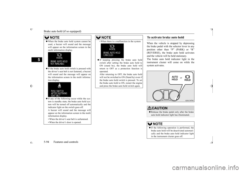
When the vehicle is
stopped by depressing
the brake pedal with the selector lever in any position other than “P” (PARK) or “R”and the vehicle will be
held stationary.
The brake auto hold indicator light in the instrument cluster will come on while thesystem activates.
NOTE
When the brake auto hold system cannot be used, a buzzer will sound and the messagewill appear on the information screen in themulti information display. If the brake auto hold
switch is pressed with
the driver’s seat belt is not fastened, a buzzer will sound and the me
ssage will appear on
the information screen in the multi informa- tion display. If any of the following occur while the sys- tem is standby state, the brake auto hold sys-tem will be turned off automatically and the indicator light on the switch goes off. A buzzer will sound
and the message will
appear on the information screen in the multi information display. • When the driver’s seat
belt is unfastened.
• When the driver’s door is opened.
• When there is a malfunction in the system If keeping pressing the brake auto hold switch after setting the brake auto hold to ON (stand by), the brake auto hold willreturn to OFF as a protection function is operated. After returning to OFF, the brake auto holdwill not be switched to ON (Stand by) even if the brake auto hold switch is pressed. To set the brake auto hold to ON, restart the engineand press the brake auto hold switch again.NOTE
To activate brake auto hold
CAUTION Release the brake pedal only after the brake auto hold indicator li
ght has illuminated.
NOTE
If the following operation is performed, the brake auto hold will be deactivated automati- cally and the brake au
to hold indicator light
in the instrument cluster goes off.
or
BK0239700US.book 94 ページ 2016年6月16日 木曜日 午前10時58分
Page 177 of 521
Brake assist system 5-96 Features and controls
5
N00562701128
1. Stop the vehicle completely using the brake pedal. 2. Release the brake pedal and the hill startassist will maintain the braking force applied while stopped
for approximately 2
seconds.
3. Depress the accelera
tor pedal and the hill
start assist will gr
adually decrease the
braking force as the vehicle starts moving.
N00562801103
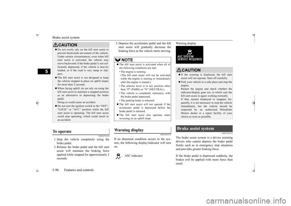
If an abnormal condition occurs in the sys-tem, the following disp
lay/indicator will turn
on.
Warning display
N00567301132
The brake assist system
is a device assisting
drivers who cannot depress the brake pedal firmly such as in em
ergency stop situations
and provides greater braking force. If the brake pedal is depressed suddenly, the brakes will be applied
with more force than
usual.
CAUTION Do not overly rely on th
e hill start assist to
prevent backwards movement of the vehicle.Under certain circumstances, even when hillstart assist is activated, the vehicle may move backwards if the brake pedal is not suf- ficiently depressed, if
the vehicle is heavily
loaded, or if the road is very steep or slip- pery. The hill start assist
is not designed to keep
the vehicle stopped in
place on uphill slopes
for more than 2 seconds. When facing uphill, do not rely on using the hill start assist to ma
intain a stopped position
as an alternative to depressing the brake pedal. Doing so could cause an accident. Do not turn the igniti
on switch to the “OFF”,
“LOCK” or “ACC” pos
ition while the hill
start assist is operating. The hill start assist could stop operating, wh
ich could result in
an accident.
To operate
NOTE
The hill start assist is activated when all of the following conditions are met. • The engine is running. (The hill start assist
will not be activated
while the engine is st
arting or immediately
after the engine is started.) • The selector lever is
in any position other
than
Page 178 of 521
Anti-lock braking system
Features and controls 5-97
5
N00517900240
The anti-lock braking system helps prevent the wheels from locking up when braking.This helps maintain vehicle drivability and steering wheel handling. When using the anti-lock brakes (sudden braking), steering is slightly different from normal driving conditions. Use the steering wheel carefully. Always keep a safe distance from the vehicle in front of you. Even if your vehi- cle is equipped with
the anti-lock braking
system, leave a greater braking distance when: • Driving on gravel or snow-coveredroads. • Driving on uneven road surfaces.
Operation of anti-lock braking system is not restricted situations where brakes areapplied suddenly. This system may also prevent the wheels from locking when you drive over manholes, steel roadworkplates, road markings
, or any uneven road
surface. When the anti-lock braking system is in use, you may feel the brake pedal vibrat- ing and hear a unique sound. It may also feel as if the pedal
resists being pressed.
In this situation, si
mply hold the brake
pedal down firmly. Do not pump thebrake, which will result in reduced braking performance.
CAUTION The brake assist system is not a device designed to exercise
braking force greater
than its capacity. Make sure to always keep asufficient distance be
tween your vehicle and
a vehicle in front of
you without relying too
much on the brake assist system.NOTE
Once the brake assist system is operational, it maintains great braking force even if the brake pedal is lightly released. To stop its operation, completely removeyour foot from the brake pedal. The brake assist system may become opera- tional when the brake pedal is fully depressed even if it
has not been depressed
suddenly. When the brake assist system is in use while driving, you may feel as if the depressedbrake pedal is soft, the pedal moves in small motions in conjunction with the operation noise, or the vehicle body and the steeringwheel vibrate. This occurs when the brake assist system is ope
rating normally and does
not indicate faulty
operation. Continue to
depress the brake pedal. You may hear an operation noise when the brake pedal is suddenl
y or fully depressed
while stationary. This does not indicate a malfunction and the brake assist system is operating normally.
When the anti-lock brake system warning light or only active st
ability control warning
light illuminate, the brake assist system innot functioning.
Anti-lock braking system Driving hints
NOTE
CAUTION The anti-lock braking system cannot prevent accidents. It is your
responsibility to take
safety precautions a
nd to drive carefully.
To prevent failure of the anti-lock braking system, be sure all 4 wheels and tires are the same size and the same type.NOTE
A whining sound is emitted from the engine compartment when driving immediately after starting the engine. These are the nor-mal sounds the anti-lock braking system makes when performing a self-check. It does not indicate
a malfunction.
BK0239700US.book 97 ページ 2016年6月16日 木曜日 午前10時58分
Page 179 of 521
Anti-lock braking system 5-98 Features and controls
5
N00531601684
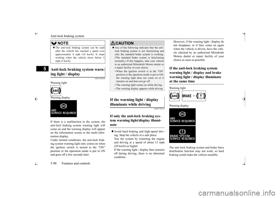
Warning light Warning display If there is a malfunction in the system, the anti-lock braking system warning light will come on and the warning display will appearon the information screen in the multi-infor- mation display. Under normal conditions, the anti-lock brak-ing system warning light only comes on when the ignition switch is turned to the “ON”and goes off a few seconds later.
N00531701614
Avoid hard braking and high-speed driv- ing. Stop the vehicl
e in a safe place.
Test the system by restarting the engineand driving at a speed of about 12 mph (20 km/h) or higher. If the warning light / display then remainsoff during driving, there is no abnormal condition.
However, if the warning light / display do not disappear, or if they come on againwhen the vehicle is driven, have the vehi- cle checked by an authorized Mitsubishi Motors dealer or repair facility of yourchoice as soon
as possible.
Warning light
Warning display The anti-lock braking system and brake force distribution function ma
y not work, so hard
braking could make the vehicle unstable.
The anti-lock braking system can be used after the vehicle has
reached a speed over
approximately 6 mph (10 km/h). It stopsworking when the vehicle slows below 3 mph (5 km/h).
Anti-lock braking system warn- ing light / display
NOTE
CAUTION Any of the following i
ndicates that the anti-
lock braking system is not functioning andonly the standard brake system is working.(The standard brake system is functioning normally.) If this happens, take your vehicle to an authorized Mitsubishi Motors dealer ora repair facility
of your choice.
• When the ignition switch is in the “ON” position or the operation mode is put in ON, the warning light doe
s not come on or it
remains on and does not go off• The warning light comes on while driving• The warning display appears while driving
If the warning light / display illuminate while driving If only the anti-lock braking sys- tem warning light/display illumi-nate
If the anti-lock braking system warning light / display and brake warning light / display illuminate at the same time
BK0239700US.book 98 ページ 2016年6月16日 木曜日 午前10時58分