fuse MITSUBISHI OUTLANDER 2019 Owner's Manual (in English)
[x] Cancel search | Manufacturer: MITSUBISHI, Model Year: 2019, Model line: OUTLANDER, Model: MITSUBISHI OUTLANDER 2019Pages: 451, PDF Size: 58.02 MB
Page 4 of 451
Instruments and controls 1-1
1
Overview
N00100202847
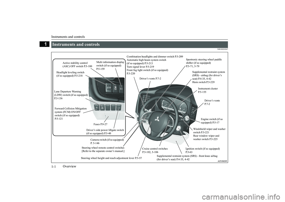
Instruments and controls
Combination headlights an
d dimmer switch P.5-209
Automatic high beam system switch (if so equipped) P.5-213 Turn signal lever P.5-219 Front fog light switc
h (if so equipped)
P.5-220
Steering wheel remote control switches [Refer to the separate owner’s manual.]
Active stability control (ASC) OFF switch P.5-100
Supplemental restraint system (SRS) - airbag (for driver’s seat) P.4-35, 4-42 Horn switch P.5-229
Instrument cluster P.5-155
Windshield wiper and washer switch P.5-221 Rear window wiper and washer switch P.5-225
Cruise control switches P.5-102, 5-106
Steering wheel height and reach adjustment lever P.5-57
Engine switch (if so equipped) P.5-17
Driver’s vents P. 7 - 2
Sportronic steering wheel paddle shifter (if so equipped) P.5-71, 5-79
Driver’s vents P.7-2
Multi information display switch (if so equipped) P.5-159
Headlight leveling switch (if so equipped) P.5-218
Driver’s side power liftgate switch (if so equipped) P.5-40
Fuses P.9-27
Lane Departure Warning (LDW) switch (if so equipped)P.5-136 Forward Collision Mitigation system (FCM) ON/OFF switch (if so equipped)P.5-121
Supplemental restraint system (SRS) - front knee airbag (for driver’s seat) P.4-35, 4-42
Ignition switch (if so equipped) P.5-63
Camera switch (if so equipped) P. 5-146
BK0264300US.book 1 ページ 2018年2月28日 水曜日 午後5時16分
Page 29 of 451
Genuine Mitsubishi Motors parts
General information 3-7
3
N00301800141
Mitsubishi Motors manufactures high quality vehicles with an em
phasis on safety. It is
important to consult an
authorized Mitsubishi
Motors dealer before installation of any accessory which may i
nvolve modification of
the electrical or fuel systems.
N00301400219
Mitsubishi Motors Genuine Parts are designed and manufacture
d to meet high stan-
dards of performance, and are recommendedfor all of your maintenance needs. Also avail- able from your Mitsubish
i Motors dealer are
a wide variety of acce
ssories to personalize
your new vehicle. Each Mitsubishi Motors
vehicle has a selection of Mitsubishi Motors authorized accessories to choose from to tai-lor your new vehicle to your own personal preference. Your Mitsubishi Motors dealer’s Parts Manager has information on variousaudio systems, protecti
on items, as well as
interior and exterior ac
cessories available for
your specific model.
N00300100017
Certain components of this vehicle, such asairbag modules, seat belt pretensioners, and button cell batteries,
may contain perchlorate
materials.Special handling may a
pply. For additional
information, see www.d
tsc.ca.gov/hazardous-
waste/perchlorate.
Modification/alterations to the electrical or fuel systems
CAUTION Please consult an au
thorized Mitsubishi
Motors dealer concerning any such acces-sory fitment or modification. If the wires interfere with the vehicle body or improper installation me
thods are used (pro-
tective fuses not included, etc.), electronic devices may be advers
ely affected, resulting
in a fire, vehicle dama
ge, or other accident.
Genuine Mitsubishi Motors parts
California Perchlorate Materials Requirements
BK0264300US.book 7 ページ 2018年2月28日 水曜日 午後5時16分
Page 122 of 451
Power liftgate (if so equipped) 5-40 Features and controls
5
N00576100038
The power liftgate can be opened automati- cally when all of the
following conditions are
met.
e “P” (PARK) position.
The power liftgate is completely closed. The power liftgate is unlocked.
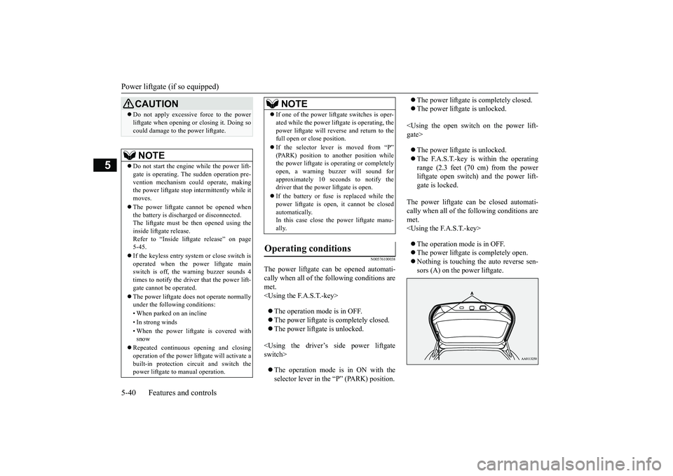
The power liftgate can be closed automati- cally when all of the
following conditions are
met.
CAUTION Do not apply excessive force to the power liftgate when opening
or closing it. Doing so
could damage to the power liftgate.NOTE
Do not start the engine while the power lift- gate is operating. The sudden operation pre- vention mechanism c
ould operate, making
the power liftgate stop
intermittently while it
moves. The power liftgate cannot be opened when the battery is discharged or disconnected. The liftgate must be then opened using the inside liftgate release.Refer to “Inside liftgate release” on page 5-45. If the keyless entry syst
em or close switch is
operated when the power liftgate main switch is off, the warning buzzer sounds 4times to notify the driver that the power lift- gate cannot be operated. The power liftgate does
not operate normally
under the following conditions: • When parked on an incline • In strong winds • When the power liftg
ate is covered with
snow
Repeated continuous opening and closing operation of the power li
ftgate will activate a
built-in protec
tion circuit and switch the
power liftgate to manual operation.
If one of the power liftgate switches is oper- ated while the power lift
gate is operating, the
power liftgate will reverse and return to thefull open or
close position.
If the selector lever is moved from “P” (PARK) position to another position while the power liftgate is
operating or completely
open, a warning buzzer will sound forapproximately 10 sec
onds to notify the
driver that the power liftgate is open. If the battery or fuse is replaced while the power liftgate is open,
it cannot be closed
automatically.In this case close th
e power liftgate manu-
ally.
Operating conditions
NOTE
BK0264300US.book 40 ページ 2018年2月28日 水曜日 午後5時16分
Page 132 of 451
Power window control 5-50 Features and controls
5
N00528801190
If a hand or head is trapped, for safety the door window is automati
cally lowered a little.
After the obstruction is removed, pull up the switch again to close the door window.
N00551400014
Wind buffeting can be de
scribed as the per-
ception of pressure on the ears or a boomingor rumbling sound. Your
vehicle may exhibit
wind buffeting when driving with one or both rear door windows down or partially opened.This is a normal occurrence that can be mini- mized. If the buffeting
occurs with the rear
door windows open, open the front door win-dows as well as the rear door windows to minimize the condition.
WA R N I N G Before driving with a child in the vehicle, be sure to lock the window switch to makeit inoperative. Children tampering withthe switch could easily trap their hands or heads in the window.
Safety mechanism
WA R N I N G If the battery terminals are disconnected or the fuse for electric window is replaced,the safety mechanism will be cancelled. If a hand or head got
trapped, a serious
injury could result.CAUTION The safety mechanism is deactivated just before the door window closes. This allowsthe door window to close completely. There- fore be especially careful that fingers are not trapped in the door window opening.
The safety mechanism is deactivated while the switch is pulled up.
Therefore be espe-
cially careful that fi
ngers are not trapped in
the door window opening. Do not deliberately tr
ap your hands or head
in order to activate the safety mechanism. Your hand or head coul
d be trapped and per-
sonal injury could result.NOTE
The safety mechanism can be activated if the driving conditions or
other circumstances
cause the door windows to
be subjected to a
physical shock similar to that caused by trapped hand or head. If the following operation is performed, the safety mechanism will be cancelled and thedoor window will not
automatically
open/close completely. • When the battery te
rminals are discon-
nected. • When the fuse for power window is replaced. • When the safety mechanism is activated five or more times consecutively.CAUTION
In such a case, the
following procedure
should be implemented to rectify this situa-tion.If the window is open,
repeatedly raise the
appropriate wi
ndow switch until that win-
dow has been fully closed.Following this, release the switch, raise the switch once again and hold it in this condi- tion for at least 1 second, then release it. Youshould now be able to
operate all windows in
the normal function.
What to do if you hear wind buffeting when driving
NOTE
BK0264300US.book 50 ページ 2018年2月28日 水曜日 午後5時16分
Page 154 of 451
Automatic transaxle (if so equipped) 5-72 Features and controls
5
To return to “D” (DRIVE) or “L” (LOW) operation, pull the spor
tronic steering wheel
paddle shifter on the + (SHIFT UP) side for longer than 2 seconds. When returning to “D” (DRIVE) or “L”(LOW) operation, the se
lector lever position
display will change to
“D” (DRIVE) or “L”
(LOW) position.
N00538801180
In sports mode, the currently selected gear isdisplayed on the information screen in themulti-information display.
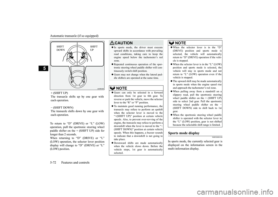
+ (SHIFT UP) The transaxle shifts up by one gear with each operation. − (SHIFT DOWN) The transaxle shifts down by one gear witheach operation.
SHIFT UP
SHIFT DOWN
CAUTION In sports mode, the driver must execute upward shifts in accordance with prevailingroad conditions, taking care to keep theengine speed below the tachometer’s red zone. Repeated continuous ope
ration of the spor-
tronic steering wheel pa
ddle shifter will con-
tinuously switch shift position. Gears may not change when the lateral pad- dle shifters are operate
d at the same time.
NOTE
Gears can only be selected in a forward direction from 1st gear to 6th gear. To reverse or park the vehi
cle, move the selector
lever to the “R” or “P” position. To maintain good running performance, the transaxle may refuse to perform an upshiftwhen the selector le
ver is moved to the
“+(SHIFT UP)” positi
on at certain vehicle
speeds. Also, to prevent over-revving of theengine, the transaxle may refuse to perform a downshift when the lever is moved to the “
−
(SHIFT DOWN)” positi
on at certain vehicle
speeds. When this happens, a buzzer soundsto indicate that a dow
nshift is not going to
take place. Downward shifts are made automatically when the vehicle slows down. Before the vehicle stops, 1st gear
is automatically
selected.
When the selector lever is in the “D” (DRIVE) position and sports mode isselected, the vehicle will automaticallyreturn to “D” (DRIVE)
operation if the vehi-
cle is stopped. When the selector lever is in the “L” (LOW) position and sports mode is selected, the vehicle will stay in
sports mode and not
return to “L” (LOW) operation even if the vehicle is stopped. The upward shift may be
made automatically
in sports mode when the engine speed rise and approach the tac
hometer’s red zone.
When pulling away fro
m a standstill on a
slippery road, pull the sportronic steeringwheel paddle shifter on the + (SHIFT UP) side to select 2nd gear
. Pull the sportronic
steering wheel paddle shifter on the
−
(SHIFT DOWN) side to shift back to 1st gear. When the sportronic
steering wheel paddle
shifter is operated with the selector lever in the “L” (LOW) position, gear is not shiftedbecause the selectable shift range is limited.
Sports mode display
NOTE
BK0264300US.book 72 ページ 2018年2月28日 水曜日 午後5時16分
Page 162 of 451
Continuously variable transmission (CVT) (if so equipped) 5-80 Features and controls
5
When returning to “D” (DRIVE) operation, the selector lever posit
ion display will change
to “D” (DRIVE) position.
N00560901067
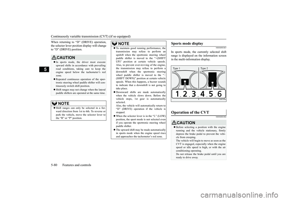
In sports mode, the currently selected shift range is displayed on the information screen in the multi-information display.
N00560801082
CAUTION In sports mode, the driver must execute upward shifts in accordance with prevailingroad conditions, taking care to keep the engine speed below the tachometer’s red zone. Repeated continuous ope
ration of the spor-
tronic steering wheel pa
ddle shifter will con-
tinuously switch shift position. Shift ranges may not change when the lateral paddle shifters are opera
ted at the same time.
NOTE
Shift ranges can only be
selected in a for-
ward direction from 1st to 6th. To reverse or park the vehicle, move
the selector lever to
the “R” or “P” position.
To maintain good running performance, the transmission may refuse to perform anupshift when the sportronic steering wheelpaddle shifter is moved to the “+(SHIFT UP)” position at cert
ain vehicle speeds.
Also, to prevent over-revving of the engine,the transmission may refuse to perform a downshift when the sportronic steering wheel paddle shifter is moved to the “
−
(SHIFT DOWN)” positi
on at certain vehicle
speeds. When this happens, a buzzer sounds to indicate that a dow
nshift is not going to
take place. Downward shifts are made automatically when the vehicle slows down. Before the vehicle stops, 1st gear
is automatically
selected.Also, the vehicle will automatically return to “D” (DRIVE) operation if the vehicle is stopped. When the selector lever is in the “L” (LOW) position, the sport mode is not selected evenif you operate the sportronic steering wheel paddle shifter. The upward shift may be made automatically in sports mode when the engine speed rises and approaches the ta
chometer’s red zone.
NOTE
Sports mode display
Operation of the CVT
CAUTIONBefore selecting a pos
ition with the engine
running and the vehicl
e stationary, firmly
depress the brake pedal to prevent the vehi- cle from creeping.The vehicle will begin to
move as soon as the
CVT is engaged, especi
ally when the engine
speed or idle speed is
high, or with the air
conditioning operating. Do not release the br
ake pedal until you are
ready to drive away.Type 1 Type 2
BK0264300US.book 80 ページ 2018年2月28日 水曜日 午後5時16分
Page 301 of 451
Turn signal lever
Features and controls 5-219
5
N00522601590
When changing lanes, or
to making a gradual
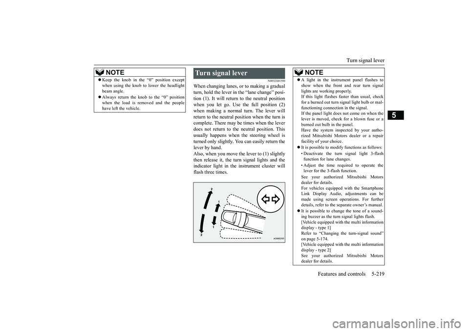
turn, hold the lever in the “lane change” posi- tion (1). It will return
to the neutral position
when you let go. Use the full position (2) when making a normal turn. The lever will return to the neutral position when the turn iscomplete. There may be times when the lever does not return to the neutral position. This usually happens when the steering wheel is turned only slightly. You
can easily return the
lever by hand.Also, when you move the lever to (1) slightly then release it, the turn signal lights and the indicator light in the instrument cluster willflash three times.
Keep the knob in the “0” position except when using the knob to lower the headlightbeam angle. Always return the knob to the “0” position when the load is removed and the peoplehave left
the vehicle.
NOTE
Turn signal lever
NOTE
A light in the instrument panel flashes to show when the front and rear turn signallights are working properly.If this light flashes fa
ster than usual, check
for a burned out turn signal light bulb or mal- functioning connection in the signal.If the panel light does not come on when the lever is moved, check for a blown fuse or a burned out bulb in the panel.Have the system inspected by your autho- rized Mitsubishi Motors dealer or a repair facility of your choice. It is possible to modi
fy functions as follows:
• Deactivate the turn signal light 3-flash function for lane changes. • Adjust the time required to operate the lever for the 3-flash function. See your authorized Mitsubishi Motors dealer for details. For vehicles equipped with the SmartphoneLink Display Audio, adjustments can be made using screen ope
rations. For further
details, refer to the
separate owner’s manual.
It is possible to change the tone of a sound- ing buzzer as the turn signal lights flash.[Vehicle equipped with the multi information display - type 1] Refer to “Changing the turn-signal sound”on page 5-174. [Vehicle equipped with the multi information display - type 2]See your authorized Mitsubishi Motors dealer for details.
BK0264300US.book 219 ページ 2018年2月28日 水曜日 午後5時16分
Page 385 of 451
9
Vehicle care and maintenanceService precautions ..........................................................................9-2 Catalytic converter ...........................................................................9-2 Engine hood .........
...........
...........
............
...........
.........
........
.........
.....9-3
View of the engine compartment .....................................................9-6 Engine oil and oil filter ....................................................................9-7 Engine coolant .................................................................................9-9Air cleaner filter .............................................................................9-10 Automatic transaxle fluid (if so equipped) .....................................9-12 Continuously variable transmission
(CVT) fluid (if so equipped) .9-12
Transfer oil (All-wheel drive models) ...........................................9-13 Rear axle oil (All-wheel drive models) .........................................9-13 Washer fluid ...................................................................................9-13Brake fluid .....................................................................................9-14 Battery ............................................................................................9-14 Tires ...............................................................................................9-16Brake pedal free play .....................................................................9-23 Parking brake lever stroke (if so equipped) ....................................9-23 Wiper blades ..................................................................................9-23Emission-control system maintenance ..........................................9-24 General maintenance .....................................................................9-25 For cold and snowy weather ..........................................................9-26Fusible links ...................................................................................9-26 Fuses ..............................................................................................9-27 Replacement of light bulbs ............................................................9-32Vehicle care precautions ................................................................9-41 Cleaning the inside of your vehicle .......
...........
...........
...........
.......9-41
Cleaning the outside of your vehicle .....
...........
...........
...........
.......9-42
BK0264300US.book 1 ページ 2018年2月28日 水曜日 午後5時16分
Page 410 of 451
For cold and snowy weather 9-26 Vehicle care and maintenance
9
The underside or rear of the vehicle is damaged
Also check the exhaust system each time the vehicle is raised for l
ubrication, oil changes,
or required service. A
ny open seams or loose
connections could le
t dangerous exhaust
fumes seep into the
luggage and passenger
compartments. Check for holes or exhaust gas leaks caused by corrosion or damage. Check the joints and connections for looseness or exhaust gas leaks. Check the rubber hangers and brackets for damage.
N00942300079
The timing belt should be replaced with anew one at the mileage listed in the “WAR- RANTY AND MAINTENANCE MAN-UAL”.
N00942501124
The hood lock release mechanism and hoodsafety catch should be
checked, cleaned, and
oiled when needed for easy movement and to prevent rust and wear. Use Multipurpose Grease NLGI Grade 2 sp
aringly for all sliding
parts of the hood latc
h and release lever.
Work the grease into the hood lock mecha- nism until all the mo
vable surfaces are cov-
ered. Also, put a light coat of the same grease onthe safety catch wherev
er moving parts touch.
N00942600102
The ventilation slots in front of the wind- shield should be brushed clear after a heavy snowfall so that the operation of the heating and ventilation systems
will not be impaired.
To prevent freezing of the weatherstripping on the doors, engine hood, etc., they should be treated with silicone grease. It is a good idea to carry a shovel or a short- handled spade in the vehicle during the win-ter so that you can clear away snow if you get stranded. A small hand-brush for sweeping snow off the vehicle a
nd a plastic scraper for
the windshield, side and rear window are also useful.
N00942700291
The fusible links will melt to prevent a fire ifa large current attempts
to flow through cer-
tain electrical systems.In case of a melted fusible link, see your authorized Mitsubishi Motors dealer or a repair facility of your
choice for inspection
and replacement. For the fusible links, pl
ease refer to “Fuse
load capacities” on page 9-28.
Check for any of the following conditions: Timing belt
Hood lock release mechanism and safety catch For cold and snowy weather Ventilation slots
Weatherstripping Additional equipment (For regions where snow is encoun- tered) Fusible links
BK0264300US.book 26 ページ 2018年2月28日 水曜日 午後5時16分
Page 411 of 451
Fuses
Vehicle care and maintenance 9-27
9
N00942801954
To prevent damage to the electrical system from short-circuiting
or overloading, each
individual circuit is e
quipped with a fuse. The
fuse blocks are locate
d in the passenger com-
partment and in the engine compartment.
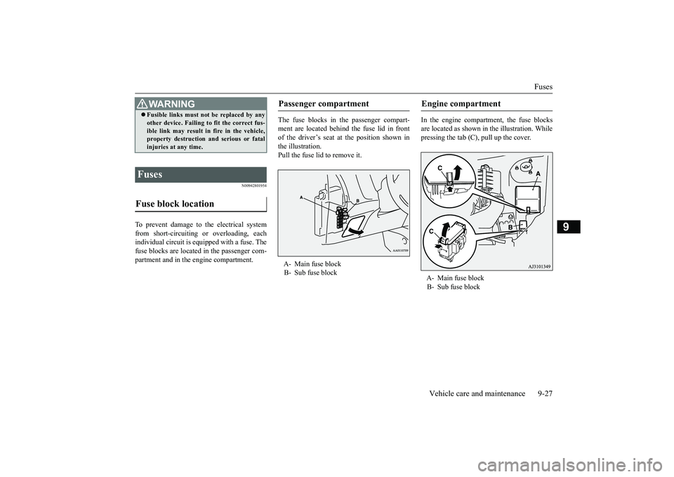
The fuse blocks in the passenger compart- ment are located behind the fuse lid in front of the driver’s seat at the position shown in the illustration.Pull the fuse lid to remove it.
In the engine compartment, the fuse blocks are located as shown in the illustration. While pressing the tab (C), pull up the cover.
WA R N I N G Fusible links must not be replaced by any other device. Failing to fit the correct fus-ible link may result in fire in the vehicle,property destruction and serious or fatal injuries at any time.
Fuses Fuse block location
Passenger compartment A- Main fuse block B- Sub fuse block
Engine compartment A- Main fuse block B- Sub fuse block
BK0264300US.book 27 ページ 2018年2月28日 水曜日 午後5時16分