lock MITSUBISHI OUTLANDER III 2016 Owner's Manual
[x] Cancel search | Manufacturer: MITSUBISHI, Model Year: 2016, Model line: OUTLANDER III, Model: MITSUBISHI OUTLANDER III 2016Pages: 464, PDF Size: 60.77 MB
Page 47 of 464
Seat belts
Seat and restraint systems 4-21
4
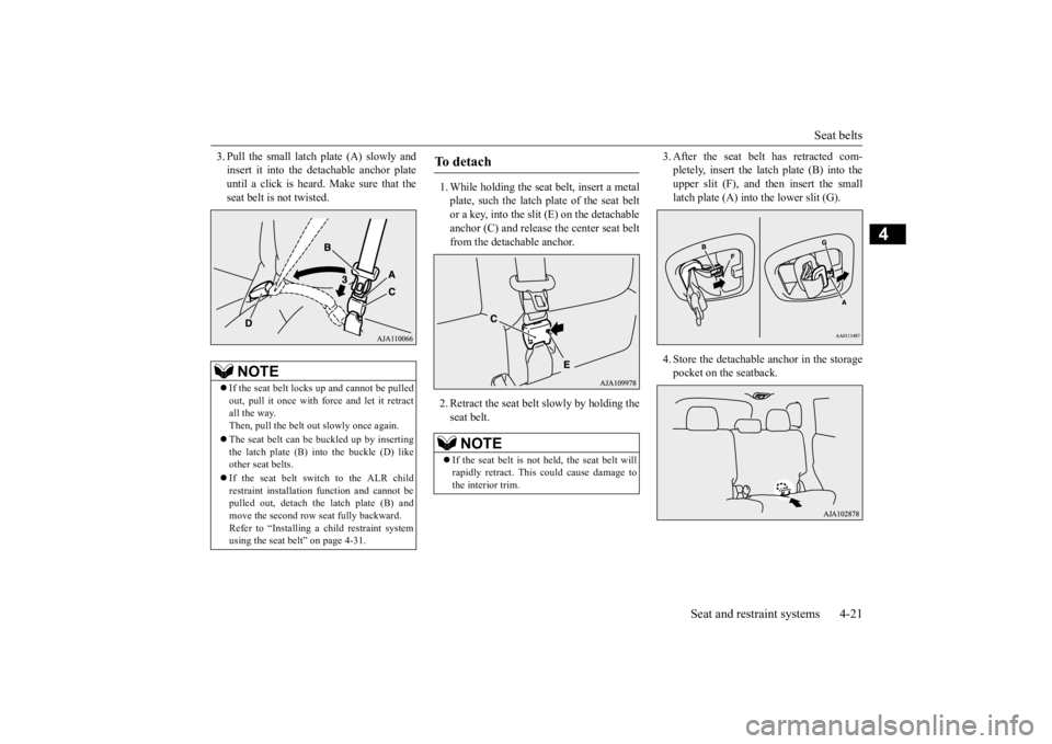
3. Pull the small latch plate (A) slowly and insert it into the detachable anchor plateuntil a click is heard. Make sure that the seat belt is not twisted.
1. While holding the seat
belt, insert a metal
plate, such the latch plate of the seat belt or a key, into the slit (E) on the detachable anchor (C) and release the center seat beltfrom the detachable anchor. 2. Retract the seat belt slowly by holding the seat belt.
3. After the seat belt has retracted com- pletely, insert the latch plate (B) into theupper slit (F), and th
en insert the small
latch plate (A) into the lower slit (G). 4. Store the detachable anchor in the storage pocket on the seatback.
NOTE
If the seat belt lock
s up and cannot be pulled
out, pull it once with fo
rce and let it retract
all the way.Then, pull the belt out
slowly once again.
The seat belt can be
buckled up by inserting
the latch plate (B) into the buckle (D) like other seat belts. If the seat belt switch to the ALR child restraint installation
function and cannot be
pulled out, detach the latch plate (B) andmove the second row seat fully backward. Refer to “Installing a child restraint system using the seat be
lt” on page 4-31.
To d e t a c h
NOTE
If the seat belt is not held, the seat belt will rapidly retract. This
could cause damage to
the interior trim.
BK0223400US.book 21 ページ 2015年2月13日 金曜日 午後12時15分
Page 49 of 464
Seat belts
Seat and restraint systems 4-23
4
N00406301354
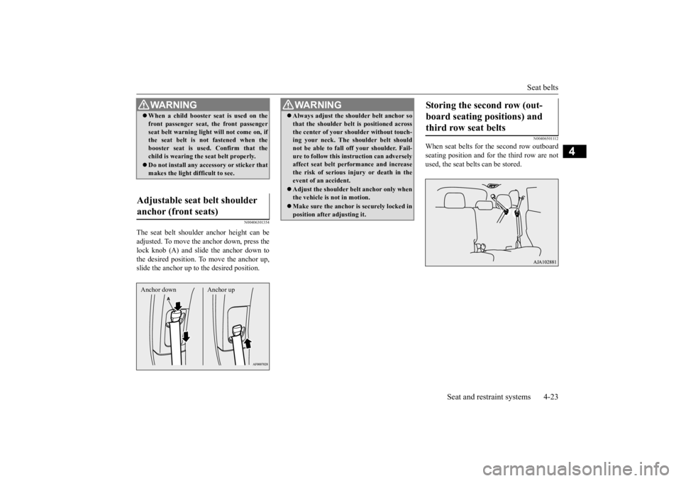
The seat belt shoulder
anchor height can be
adjusted. To move the anchor down, press thelock knob (A) and slide the anchor down to the desired position. To
move the anchor up,
slide the anchor up to the desired position.
N00406501112
When seat belts for the second row outboardseating position and for the third row are not used, the seat belts can be stored.
WA R N I N G When a child booster se
at is used on the
front passenger seat, the front passengerseat belt warning ligh
t will not come on, if
the seat belt is not fastened when the booster seat is used
. Confirm that the
child is wearing the seat belt properly. Do not install any acce
ssory or sticker that
makes the light difficult to see.
Adjustable seat belt shoulder anchor (front seats) Anchor down Anchor up
WA R N I N G Always adjust the shou
lder belt anchor so
that the shoulder belt
is positioned across
the center of your shoulder without touch-ing your neck. The sh
oulder belt should
not be able to fall off your shoulder. Fail- ure to follow this instruction can adverselyaffect seat belt performance and increase the risk of serious in
jury or death in the
event of an accident. Adjust the shoulder be
lt anchor only when
the vehicle is not in motion. Make sure the anchor is securely locked in position after adjusting it.
Storing the second row (out- board seating positions) and third row seat belts
BK0223400US.book 23 ページ 2015年2月13日 金曜日 午後12時15分
Page 57 of 464
Child restraint systems
Seat and restraint systems 4-31
4
N00407301494
With the exception of the driver, the seat belt in all other seating pos
itions can be converted
from normal Emergency Locking Retractor(ELR) mode, to Automatic Locking Retractor (ALR) mode. This means that when you pull the seat belt fully out of the retractor, the retractor will switch to its ALR child restraint installation function.
Always use the ALR
child restraint installation function when you install a child restraint system using the seat belt.Children 12 years old and under should always be restrained in the rear seat, when- ever possible, although the front passengerseat belt can also be converted to ALR mode.
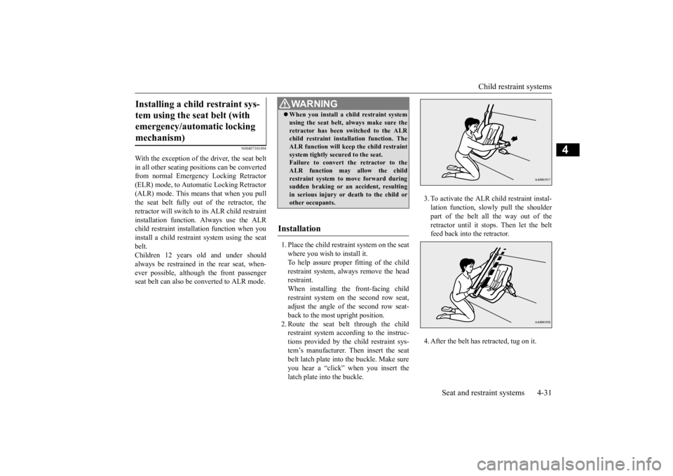
1. Place the child restraint system on the seat where you wish to install it. To help assure proper fitting of the child restraint syst
em, always remove the head
restraint. When installing the front-facing child restraint system on the second row seat,adjust the angle of the second row seat- back to the most upright position. 2. Route the seat belt through the childrestraint system according to the instruc- tions provided by the child restraint sys- tem’s manufacturer. Then insert the seatbelt latch plate into
the buckle. Make sure
you hear a “click” when you insert the latch plate into the buckle.
3. To activate the ALR child restraint instal- lation function, slow
ly pull the shoulder
part of the belt all the way out of the retractor until it stops. Then let the belt feed back into the retractor. 4. After the belt has retracted, tug on it.
Installing a child restraint sys- tem using the seat belt (with emergency/automatic locking mechanism)
WA R N I N G When you install a child restraint system using the seat belt, always make sure theretractor has been switched to the ALRchild restraint installation function. The ALR function will keep the child restraint system tightly secured to the seat.Failure to convert the retractor to the ALR function may allow the child restraint system to move forward duringsudden braking
or an accide
nt, resulting
in serious injury or
death to the child or
other occupants.
Installation
BK0223400US.book 31 ページ 2015年2月13日 金曜日 午後12時15分
Page 58 of 464
Child restraint systems 4-32 Seat and restraint systems
4
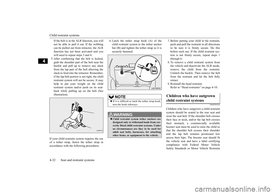
If the belt is in the ALR function, you will not be able to pull it out. If the webbingcan be pulled out from retractor, the ALR function has not been activated and you will need to repeat steps 3 and 4.5. After confirming that the belt is locked, grab the shoulder part of the belt near the buckle and pull up to remove any slackfrom the lap part of the belt allowing the slack to feed into the retractor. Remember, if the lap belt portion is not tight, the child restraint system will
not be secure. It may
help to put your weight on the childrestraint system and/or push on its seat- back while pulling up on the belt (See illustration).
6. Latch the tether strap hook (A) of the child restraint system to the tether anchorbar (B) and tighten the tether strap so it is securely fastened.
7. Before putting your child in the restraint, push and pull the restraint in all directionsto be sure it is firmly secure. Do this before each use. If
the child restraint sys-
tem is not firmly se
cure, repeat steps 1
through 6. 8. To remove a child restraint system from the vehicle and deactivate the ALR mode,remove the child from the restraint. Unlatch the buckle. Then remove the belt from the restraint and let the belt fully retract. 9. Reinstall the head restraint.Refer to “Head restraints” on page 4-10.
N00407601628
Children who have outgrown a child restraint system should be
seated in the rear seat and
wear the seat belt. If the shoulder belt crossestheir face or neck, and/or the lap belt crosses their stomach, a commercially available booster seat must be used
to raise the child so
that the shoulder belt
crosses their shoulder
and the lap belt re
mains positioned low
across their hips. The
booster seat should fit
the vehicle seat and ha
ve a label certifying
compliance with Federal Motor Vehicle Safety Standards or Motor Vehicle Restraint
If your child restraint system requires the use of a tether strap, fasten the tether strap inaccordance with the following procedures.
NOTE
If it is difficult to
latch the tether strap hook,
turn the hook sideways.WA R N I N G Child restraint system tether anchors are designed only to with
stand loads from cor-
rectly fitted child restraint systems. Underno circumstances are they to be used for adult seat belts, harnesses, for attaching other items, or equipment to the vehicle.
Children who have outgrown child restraint systems
BK0223400US.book 32 ページ 2015年2月13日 金曜日 午後12時15分
Page 59 of 464
Maintenance and inspection of seat belts
Seat and restraint systems 4-33
4
Systems and Booster Seats Safety Regula- tions.
N00407000221
The seat belt webbing
may be cleaned with
mild soap or detergent solution. Do not use anorganic solvent. Allow the belts to dry in the shade. Do not allow them to retract until com- pletely dry. Do not attempt to bleach or re-dye the belts. The color may rub off and the webbing strength may be affected.
Regularly check your seat belt buckles and their release mechanisms for positive engage-ment and release of the latch plate. Check the retractors for automatic locking when in the Automatic Locking Retractor function. The entire seat belt assembly should be replaced if the webbing shows any obvious cuts, tears, increase in thickness in any sec- tion of the webbing from broken fibers, orsevere fading from sunl
ight. All of these con-
ditions indicate a we
akening of the belt,
which may adversely affect seat belt perfor- mance in an accident.
N00407701788
This vehicle is equippe
d with a Supplemental
Restraint System (SRS), which includes air- bags for the driver and passengers.
The SRS front airbags are designed to supple- ment the primary protection of the driver andfront passenger seat
belt systems by provid-
ing those occupants wi
th protection against
head and chest injuries
in certain moderate to
severe frontal collisions. The SRS front air- bags, together with sens
ors at the front of the
vehicle and sensors attached to the frontseats, form an advanced airbag system. The SRS side airbags and the curtain airbags are also designed to supplement the seat belts. The SRS side airbags provide the driver and front passenger with protection against chest injuries by deploying the bag on the sideimpacted in moderate
to severe side impact
collisions. The SRS curtain airbags provide the driver and the passengers on the front seatand the second row outboard seats with pro- tection against head injuries by deploying the curtain airbag on the si
de impacted in moder-
ate to severe side imp
act collisions and by
deploying both curtain
airbags when a roll-
over is detected. The curtain airbags are alsodesigned to help reduce the risk of complete and partial ejection fro
m the vehicle through
side windows in both side impact and roll-over type accidents. The SRS airbags are NOT a substitute for use of the seat belts. For maximum protection in all types of accident
s, seat belts must
ALWAYS be worn by everyone who drives or
WA R N I N G Any child who is t
oo small to properly
wear a seat belt must be properly restrained in an appropriate child restraint system, to reduce their risk ofserious injury or de
ath in an accident.
A child should never be left unattended in, or unsupervised around, your vehicle. When you leave the ve
hicle, always take
the child out as well. Children can die from heat stroke if left or trapped inside the vehicle, especially onhot days. Keep your vehicle locked when not in use. Keep your vehicle ke
ys away from chil-
dren.
Maintenance and inspection of seat belts
WA R N I N G Do not attempt to repair or replace any part of the seat belt assemblies. This workshould be done by an authorized Mitsubishi Motors deal
er. Failure to have
an authorized Mitsub
ishi Motors dealer
perform the work could reduce the effec- tiveness of the belts and could result in a serious injury or de
ath in an
accident.
Supplemental Restraint Sys- tem (SRS) - airbag
BK0223400US.book 33 ページ 2015年2月13日 金曜日 午後12時15分
Page 77 of 464
5
Features and controlsBreak-in recommendations ..............................................................5-3 Keys .................................................................................................5-3 Electronic immobilizer (Anti-theft starting system) ........................5-4Keyless entry system (if so equipped) ..............................................5-7 Free-hand Advanced Security Tr
ansmitter (F.A.S.T.-key) (if so
equipped).....................................................................................5-12Door locks ......................................................................................5-33 Power door locks ......
...........
...........
...........
...........
...........
.........
.....5-35
Child safety locks for rear door ..........
...........
.........
.........
.........
.....5-36
Liftgate (except for vehi
cles equipped with the
power liftgate) ....5-36
Power liftgate (if so equipped) .......................................................5-38 Inside liftgate release .....................................................................5-44Theft-alarm system ........................................................................5-45 Power window control ...................................................................5-49 Sunroof (if so equipped) .................................................................5-51Parking brake .................................................................................5-53 Steering wheel height and reach adjustment ..................................5-54 Inside rearview mirror ...................................................................5-55Outside rearview mirrors ...............................................................5-57 Ignition switch ...............................................................................5-60 Steering wheel lock (if so equipped) ..............................................5-62Starting the engine .........................................................................5-62 Automatic transaxle (if so equipped)..............................................5-64 Continuously variable transmission
(CVT) (if so equipped)..........5-71
Electronically controlled
4WD system (if so equipped).................5-79
S-AWC (Super-All Wheel Control) (if
so equipped) .....................5-81
4-wheel drive operation .................................................................5-85Inspection and maintenance followi
ng rough road operation ........5-87
Cautions on the handling of 4-wheel dr
ive vehicles ..................... 5-88
Service brake ................................................................................. 5-89 Hill start assist (if so equipped) ...................................................... 5-89Brake assist system ........................................................................ 5-90 Anti-lock braking system .............................................................. 5-91 Electric power steering system (EPS) ........................................... 5-93Active stability control (ASC) ....................................................... 5-94 Cruise control (if so equipped) ....................................................... 5-96 Adaptive Cruise Control System (ACC)
(if so equipped) ............ 5-100
Forward Collision Mitigation System
(FCM) (if so equipped) .... 5-111
Lane Departure Warning System (LDW
) (if so equipped)........... 5-116
Tire pressure monitoring system ................................................. 5-119Rear-view camera (if so equipped)............................................... 5-124 Instrument cluster ........................................................................ 5-126 Multi Information display - Type 1 ............................................. 5-128Multi Information display - Type 2 ............................................. 5-146 Indicator light, warning light, and
information screen display list
(multi information display - Type 1) ....................................... 5-154Indicator and warning light package
(multi information display - Type
2) .............................................................................................. 5-171 Indicators ..................................................................................... 5-172Warning lights .............................................................................. 5-173 Information screen display (Vehicle equipped with the multi informa- tion display - Type 1) ............................................................... 5-175Combination headlights and dimmer switch ............................... 5-177 Headlight leveling switch (if so equipped)................................... 5-182 Turn signal lever .......................................................................... 5-183Hazard warning flasher switch .................................................... 5-184
BK0223400US.book 1 ページ 2015年2月13日 金曜日 午後12時15分
Page 79 of 464
Break-in recommendations
Features and controls 5-3
5
N00508701366
Advanced automobile
manufacturing tech-
niques permit you to operate your new vehi- cle without requiring a long break-in periodof low-speed driving. However, you can add to the future perfor- mance and economy of your vehicle byobserving the following precautions during the first 300 miles (500 km). Drive your vehicle at m
oderate speeds during
the break-in period. Avoid revving the engine. Avoid rough driving such as sudden starts, sudden accelerati
on, prolonged high-
speed driving and sudden braking. These actions would have a detrimental effect onthe engine and lead to increased fuel and oil consumption; th
is could ultimately
result in the malfunction of engine com-ponents. Be particularly careful to avoid full acceleration while in low shift posi- tion (low gears). Do not overload the vehicle. Stay within the seating capacity. (Refer to “Cargo load precautions” on page 6-10.) Refrain from towing a trailer or other vehicle (Refer to “T
railer towing” on page
6-11).
N00508801628
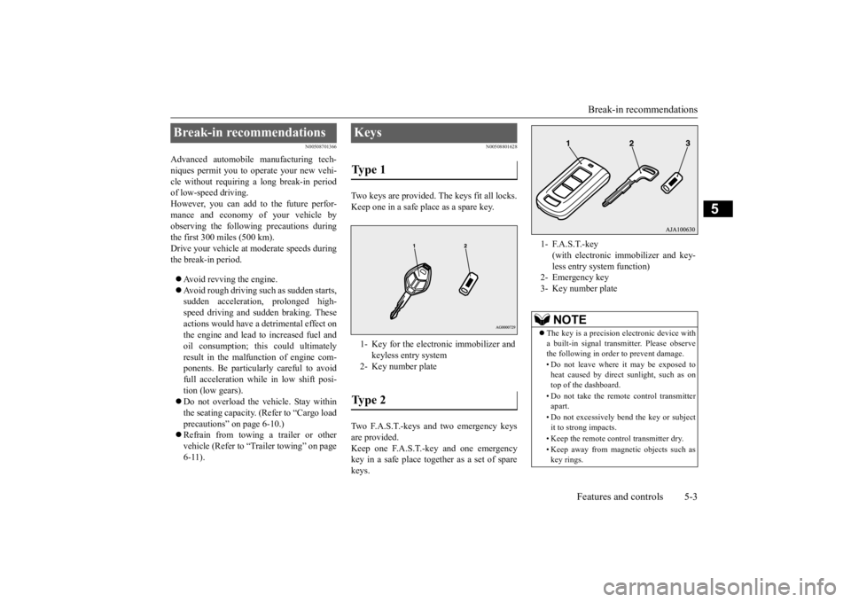
Two keys are provided. The keys fit all locks. Keep one in a safe place as a spare key. Two F.A.S.T.-keys and two emergency keys are provided. Keep one F.A.S.T.-key and one emergency key in a safe place together as a set of sparekeys.
Break-in recommendations
Keys Ty p e 1 1- Key for the electronic immobilizer and
keyless entry system
2- Key number plateTy p e 2
1- F.A.S.T.-key
(with electronic im
mobilizer and key-
less entry system function)
2- Emergency key3- Key number plate
NOTE
The key is a precision
electronic device with
a built-in signal transm
itter. Please observe
the following in order to prevent damage. • Do not leave where it may be exposed to heat caused by direct
sunlight, such as on
top of the dashboard. • Do not take the remote
control transmitter
apart. • Do not excessively bend the key or subject it to strong impacts. • Keep the remote control transmitter dry. • Keep away from magne
tic objects such as
key rings.
BK0223400US.book 3 ページ 2015年2月13日 金曜日 午後12時15分
Page 80 of 464
![MITSUBISHI OUTLANDER III 2016 Owners Manual Electronic immobilizer (Anti-theft starting system) 5-4 Features and controls
5
N00509101790
[For vehicles equippe
d with the Free-hand
Advanced Security Transmitter (F.A.S.T.-key)] For information MITSUBISHI OUTLANDER III 2016 Owners Manual Electronic immobilizer (Anti-theft starting system) 5-4 Features and controls
5
N00509101790
[For vehicles equippe
d with the Free-hand
Advanced Security Transmitter (F.A.S.T.-key)] For information](/img/19/58143/w960_58143-79.png)
Electronic immobilizer (Anti-theft starting system) 5-4 Features and controls
5
N00509101790
[For vehicles equippe
d with the Free-hand
Advanced Security Transmitter (F.A.S.T.-key)] For information on ope
rations for vehicles
equipped with the Free-hand Advanced Secu-rity Transmitter (F.A
.S.T.-key), refer to
“Free-hand Advanced
Security Transmitter
(F.A.S.T.-key): Electr
onic immobilizer (Anti-
theft starting system)” on page 5-18. [Except for vehicles e
quipped with the Free-
hand Advanced Secu
rity Transmitter
(F.A.S.T.-key)]The electronic immobilize
r is designed to sig-
nificantly reduce the
possibility of vehicle
theft. The purpose of the system is to immo-bilize the vehicle if an invalid start is
attempted. A valid st
art attempt can only be
achieved (subject to ce
rtain conditions) using
a key “registered” to the immobilizer system. All of the keys provided with your new vehi- cle have been program
med to the vehicle’s
electronics.
• Keep away from devi
ces that produce mag-
netism, such as audio systems, computersand televisions. • Keep away from devices that emit strong electromagneti
c waves, such as cellular
phones, wireless devices and high fre- quency equipment (i
ncluding medical
devices). • Do not clean with
ultrasonic cleaners.
• Do not leave the key where it may be exposed to high temperature or high humid- ity.
If you lose your key, to prevent the theft of the vehicle immediatel
y contact an autho-
rized Mitsubishi Motors dealer. If you notify an authorized Mitsubishi Motors dealer of the key number, they canmake a new key. The key number is stamped on the key number plate. Keep the key num- ber plate in a safe pl
ace separate from the
key itself. No keys other than those registered in advance can be used to start the engine. Refer to “Electronic immobilizer (Anti-theft starting system)” on page 5-4.Refer to “Free-hand Advanced Security Transmitter (F.A.S.T.-key): “Electronic immobilizer (Anti-theft starting system)” onpage 5-18.NOTE
When the theft-alarm is in the system opera- tional status, the alarm operates if a door orliftgate is opened after using the key, thedoor lock knob or the power door lock switch to unlock the vehicle. The system does not enter the preparation status if the keyless entry system or the F.A.S.T.-key operation was not used to lockthe vehicle.
Electronic immobilizer (Anti-theft starting system)
NOTE
NOTE
In the following cases, the vehicle may not be able to recognize
the registered ID code
from the key. This mean
s the engine will not
start even when the key is turned to the “START” position. • When the key contacts a key ring or other metallic or ma
gnetic object
BK0223400US.book 4 ページ 2015年2月13日 金曜日 午後12時15分
Page 81 of 464
Electronic immobilizer (Ant
i-theft starting system)
Features and controls 5-5
5
Only keys that have been programmed to the vehicle’s electronics can be used to start the vehicle. If you lose the key, you can order a key from your authorized Mitsubi
shi Motors dealer by
referring to the key number. To prevent vehicle theft, the ID code for thevehicle keys must be changed.
Take your vehicle and
all remaining keys to
your authorized Mitsubishi Motors dealer tohave your ID code changed. To add a key, you must already have 2 regis- tered keys. You need to register the ID code to the vehicle. Registering the ID code can be done by your- self (except for vehicles
sold in Canada), or
by your authorized Mitsubishi Motors dealer.For you to register the ID code yourself, fol- low the “Customer key programming” proce- dure below.If you choose to have
your authorized Mit-
subishi Motors dealer register the ID code, take your vehicle and
all remaini
ng keys to
your authorized Mitsubishi Motors dealer.
• When the key grip
contacts metal of
another key • When the key contacts
or is close to other
immobilizer keys (inc
luding keys of other
vehicles)
In cases like the a
bove, move the offending
object(s) away from the key and turn the keyback to the “ACC” or “LOCK” position. Then try to start the engine again. If the engine does not start,
contact an authorized
Mitsubishi Motors dealer. The key may not operate
properly when it is
near an object or faci
lity that emits strong
electromagne
tic waves.
NOTE
Electronic immobilize
r is not compatible
with commercially available remote startingsystems. Use of commercially availableremote starting systems may result in vehicle starting problems
and a loss of security pro-
tection. A system failure is suspected when the igni- tion switch is turned to the “START” posi-tion, and the engine does
not start. In such a
case, contact an au
thorized Mitsubishi
Motors dealer.CAUTION Do not make any altera
tions or additions to
the immobilizer system.
Alterations or addi-
tions could cause failure
of the immobilizer.
Replacement keys
NOTE
Additional keys
NOTE
You are provided with 2 keys, but you may register up to 8 keys.
BK0223400US.book 5 ページ 2015年2月13日 金曜日 午後12時15分
Page 82 of 464
Electronic immobilizer (Anti-theft starting system) 5-6 Features and controls
5
N00562201149
You can program new keys to the system if you have two valid (alr
eady registered) keys
and blank immobilizer ke
y (specially cut for
your vehicle at your Mitsubishi Motorsdealer) by doing the following: 1. Insert the first valid key into the ignition switch and turn the key to the “ON” posi-tion for 5 seconds. 2. Turn the key to the “OFF” or “LOCK” position and remove the first key.3. Within 30 seconds of removing the first key, insert the second valid key into the ignition and turn it to the “ON” position.About 10 seconds la
ter, the immobilizer
display will start to blink.
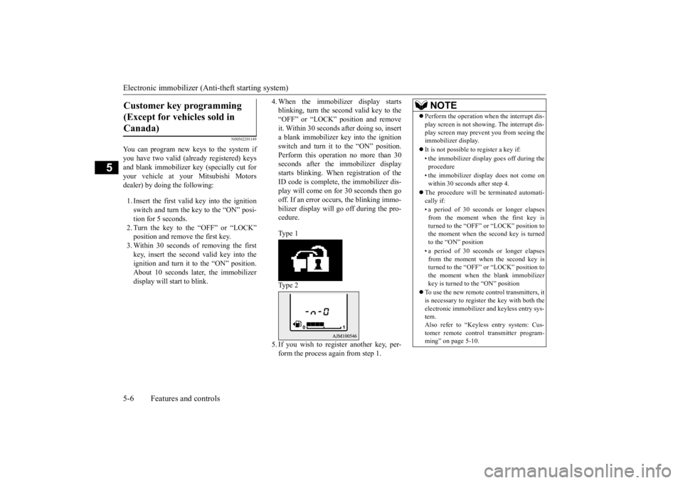
4. When the immobilizer display starts blinking, turn the second valid key to the“OFF” or “LOCK” position and remove it. Within 30 seconds after doing so, insert a blank immobilizer ke
y into the ignition
switch and turn it to the “ON” position. Perform this operation no more than 30 seconds after the immobilizer displaystarts blinking. When registration of the ID code is complete, the immobilizer dis- play will come on for 30 seconds then go off. If an error occurs, the blinking immo- bilizer display will
go off during the pro-
cedure. Type 1 Type 2 5. If you wish to register another key, per- form the process again from step 1.
Customer key programming (Except for vehicles sold in Canada)
NOTE
Perform the operation when the interrupt dis- play screen is not show
ing. The interrupt dis-
play screen may prevent you from seeing theimmobilizer display. It is not possible to
register a key if:
• the immobilizer disp
lay goes off during the
procedure • the immobilizer disp
lay does not come on
within 30 seconds after step 4.
The procedure will be terminated automati- cally if: • a period of 30 seconds or longer elapses from the moment when the first key isturned to the “OFF” or “LOCK” position to the moment when the second key is turned to the “ON” position • a period of 30 seconds or longer elapses from the moment when the second key isturned to the “OFF” or “LOCK” position to the moment when the blank immobilizer key is turned to the “ON” position
To use the new remote control transmitters, it is necessary to register
the key with both the
electronic immobilizer
and keyless entry sys-
tem. Also refer to “Keyless entry system: Cus-tomer remote control transmitter program- ming” on page 5-10.
BK0223400US.book 6 ページ 2015年2月13日 金曜日 午後12時15分