turn signal MITSUBISHI OUTLANDER PHEV 2014 (in English) Owner's Guide
[x] Cancel search | Manufacturer: MITSUBISHI, Model Year: 2014, Model line: OUTLANDER PHEV, Model: MITSUBISHI OUTLANDER PHEV 2014Pages: 442, PDF Size: 19.04 MB
Page 180 of 442
Automatic headlamp levelling(vehicles with discharge head- lamps)
E00517601564
This mechanism automatically adjusts the di-
rection of the headlamps (beam position) de-
pending on changes in the condition of the
vehicle, such as the number of occupants or luggage weight. When the headlamps are il-luminated with the operation mode of the
power switch in ON, the beam position of the headlamps is automatically adjusted when thevehicle stops.
Turn-signal lever
E00506502658
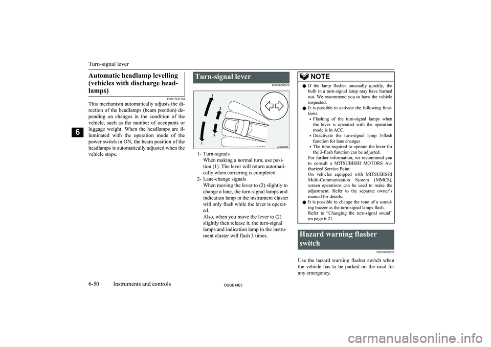
1- Turn-signalsWhen making a normal turn, use posi-
tion (1). The lever will return automati-
cally when cornering is completed.
2- Lane-change signals When moving the lever to (2) slightly to
change a lane, the turn-signal lamps and
indication lamp in the instrument cluster
will only flash while the lever is operat-
ed.
Also, when you move the lever to (2)
slightly then release it, the turn-signal
lamps and indication lamp in the instru-
ment cluster will flash 3 times.
NOTEl If the lamp flashes unusually quickly, the
bulb in a turn-signal lamp may have burned out. We recommend you to have the vehicle
inspected.
l It is possible to activate the following func-
tions.
• Flashing of the turn-signal lamps when
the lever is operated with the operation
mode is in ACC.
• Deactivate the turn-signal lamp 3-flash
function for lane changes
• The time required to operate the lever for
the 3-flash function can be adjusted.
For further information, we recommend you
to consult a MITSUBISHI MOTORS Au-
thorized Service Point.
On vehicles equipped with MITSUBISHI
Multi-Communication System (MMCS), screen operations can be used to make theadjustment. Refer to the separate owner’s
manual for details.
l It is possible to change the tone of a sound-
ing buzzer as the turn-signal lamps flash.
Refer to “Changing the turn-signal sound”
on page 6-21.Hazard warning flasher
switch E00506602037
Use the hazard warning flasher switch when
the vehicle has to be parked on the road for
any emergency.
Turn-signal lever
6-50OGGE14E5Instruments and controls6
Page 181 of 442
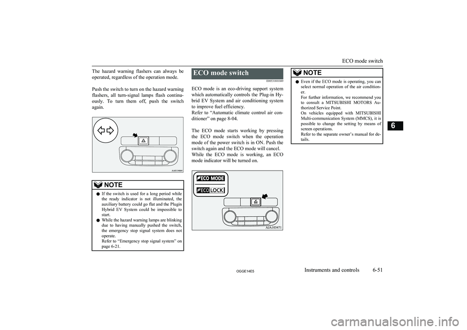
The hazard warning flashers can always beoperated, regardless of the operation mode.
Push the switch to turn on the hazard warning flashers, all turn-signal lamps flash continu-
ously. To turn them off, push the switch
again.NOTEl If the switch is used for a long period while
the ready indicator is not illuminated, theauxiliary battery could go flat and the Plugin
Hybrid EV System could be impossible to start.
l While the hazard warning lamps are blinking
due to having manually pushed the switch,
the emergency stop signal system does not
operate.
Refer to “Emergency stop signal system” on page 6-21.ECO mode switch
E00531801049
ECO mode is an eco-driving support system
which automatically controls the Plug-in Hy- brid EV System and air conditioning system to improve fuel efficiency.
Refer to “Automatic climate control air con-
ditioner” on page 8-04.
The ECO mode starts working by pressing the ECO mode switch when the operationmode of the power switch is in ON. Push the
switch again and the ECO mode will cancel. While the ECO mode is working, an ECO mode indicator will be turned on.NOTEl Even if the ECO mode is operating, you can
select normal operation of the air condition-
er.
For further information, we recommend you to consult a MITSUBISHI MOTORS Au-
thorized Service Point.
On vehicles equipped with MITSUBISHI
Multi-communication System (MMCS), it is
possible to change the setting by means of
screen operations.
Refer to the separate owner’s manual for de- tails.
ECO mode switch
6-51OGGE14E5Instruments and controls6
Page 252 of 442
NOTE2. Press and hold the LDW switch for
more than approximately 10 seconds. The “LDW 2” indicator appears on
the multi information display.
3 . Press the LDW switch, and the
“LDW” indicator on the top-right of the multi information display goes out.
To return to the “LDW 1” mode, put the sys-
tem in ‘OFF state’, press and hold the LDW switch for more than approximately 10 sec-onds. The “LDW 1” indicator appears on the
multi information display.
Standby state
In the standby mode, the system is capable of
recognizing the lane in which your vehicle is positioned and issuing audible warning whenyour vehicle goes out of the lane.
The system automatically shifts from the
‘ON state’ to the ‘standby state’ if all of the following conditions are simultaneously met.
The “LDW” indicator in the information dis-
play changes to
indicator (green).
l The vehicle speed is approximately
65 km/h (40 mph) or higher.
l The turn-signal lever is not operated.
l The hazard lamp is not activated.
l The brake pedal is not depressed.
lEnvironmental conditions are adequate
for the system to recognize the lane markings on both sides.
l The system has been placed in the ‘ON
state’.NOTEl The system stays in the “ON” state for about
7 seconds after the hazard lamp has stopped
flashing or the turn-signal lever has returned to the home position.
Lane departure warning
A buzzer sounds intermittently and indication
of “LANE DEPARTURE” appears in the in-
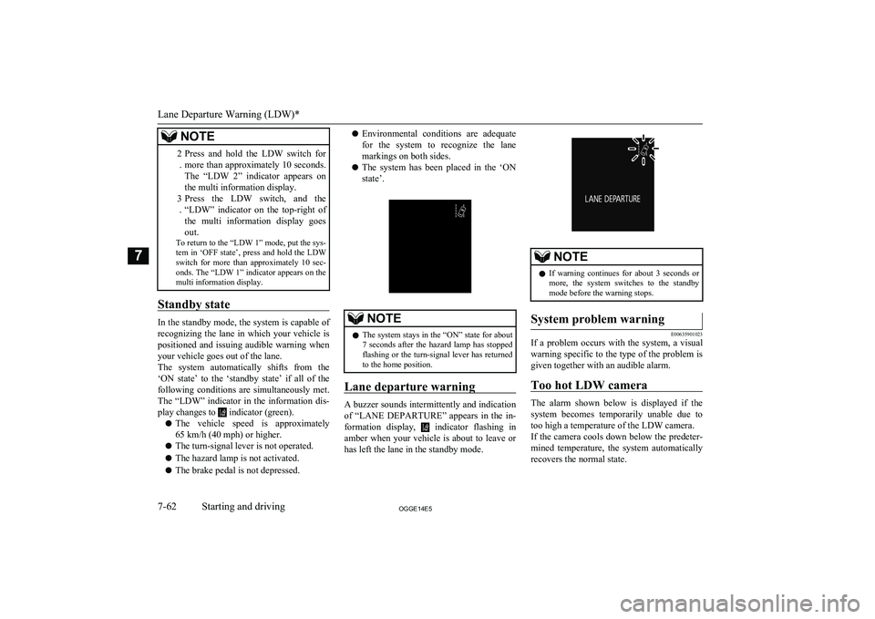
formation display,
indicator flashing in
amber when your vehicle is about to leave or has left the lane in the standby mode.
NOTEl If warning continues for about 3 seconds or
more, the system switches to the standby
mode before the warning stops.System problem warning
E00635901023
If a problem occurs with the system, a visual
warning specific to the type of the problem isgiven together with an audible alarm.
Too hot LDW camera
The alarm shown below is displayed if the system becomes temporarily unable due totoo high a temperature of the LDW camera.If the camera cools down below the predeter-
mined temperature, the system automatically
recovers the normal state.
Lane Departure Warning (LDW)*
7-62OGGE14E5Starting and driving7
Page 295 of 442
/SEL key
(counter-
clockwise)Reduces the frequency being
received./SEL key
(clockwise)Increases the frequency be-
ing received. key
(hold down)Release the button to start
seek station selection, and
when a station is received,
scanning stops. key
(hold down)
Preset Memory
Register the broadcast station in advance, and select this at a later time.
1. Tune in to the frequency to register.
2. Hold down any of the keys from the
1RPT key to the 6
key.
A “Beep” sounds, and the preset key is registered.
NOTEl The preset memory can register a maximum
of 6 stations for each band (FM1, FM2,
FM3).
l If a preset key that already has a station reg-
istered is selected, then this is overwritten with the new preset.NOTEl Pressing the preset key will select the previ-
ously registered frequency.
Auto Memory (Auto Store)
The top 6 stations with a strong signal can be
automatically registered in order with preset keys.
Hold down the RADIO key.
After completion of auto store operations, the product will receive the station registered in
the preset key [1].
CAUTIONl Please be aware that the formerly-registered
frequency in the memory will be overwrit- ten.NOTEl Using auto store for FM1 and FM2 switches
to FM3.
PTY Search
Select PTY (program content), and automati-
cally scan for stations.
1. During FM reception, press the PTY/
SCAN key.
This switches to the PTY selection mode.
2. Turn the
/SEL key to select PTY.
The PTY (program content) indicator
will flash, and station selection will au- tomatically start. When a station is re-
ceived, the station name is displayed.
NOTEl This receives the station detected first.
l 10 seconds after reception, PTY search
mode will be cancelled.Listen to DAB*
E00739100014
This explains how to listen to DAB.
To listen to DAB
1. Press the RADIO key to switch the
band.
Switch between DAB1, DAB2, and DAB3 bands.
The selected band is indicated on the display.
Listen to DAB*
8-27OGGE14E5For pleasant driving8
Page 354 of 442
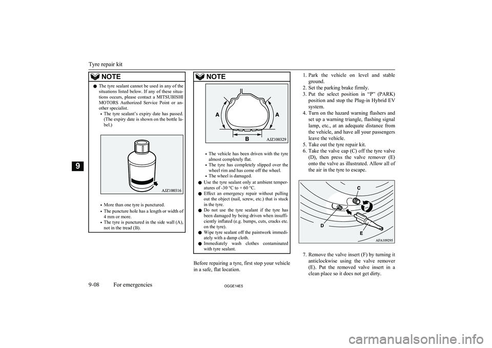
NOTElThe tyre sealant cannot be used in any of the
situations listed below. If any of these situa-
tions occurs, please contact a MITSUBISHI
MOTORS Authorized Service Point or an-
other specialist.
• The tyre sealant’s expiry date has passed.
(The expiry date is shown on the bottle la- bel.)
• More than one tyre is punctured.
• The puncture hole has a length or width of
4 mm or more.
• The tyre is punctured in the side wall (A),
not in the tread (B).
NOTE
• The vehicle has been driven with the tyre
almost completely flat.
• The tyre has completely slipped over the
wheel rim and has come off the wheel.
• The wheel is damaged.
l Use the tyre sealant only at ambient temper-
atures of -30 °C to + 60 °C.
l Effect an emergency repair without pulling
out the object (nail, screw, etc.) that is stuck
in the tyre.
l Do not use the tyre sealant if the tyre has
been damaged by being driven when insuffi- ciently inflated (e.g. bumps, cuts, cracks etc.
on the tyre).
l Wipe tyre sealant off the paintwork immedi-
ately with a damp cloth.
l Immediately wash clothes contaminated
with tyre sealant.
Before repairing a tyre, first stop your vehicle
in a safe, flat location.
1. Park the vehicle on level and stable
ground.
2. Set the parking brake firmly.
3. Put the select position in “P” (PARK)
position and stop the Plug-in Hybrid EV
system.
4. Turn on the hazard warning flashers and
set up a warning triangle, flashing signal
lamp, etc., at an adequate distance from
the vehicle, and have all your passengers
leave the vehicle.
5. Take out the tyre repair kit.
6. Take the valve cap (C) off the tyre valve
(D), then press the valve remover (E)
onto the valve as illustrated. Allow all of the air in the tyre to escape.
7. Remove the valve insert (F) by turning it
anticlockwise using the valve remover (E). Put the removed valve insert in a
clean place so it does not get dirty.
Tyre repair kit
9-08OGGE14E5For emergencies9
Page 399 of 442
NOTElIf you are unsure of how to carry out the
work as required, we recommend you to consult a specialist.
l Be careful not to scratch the vehicle body
when removing a lamp or lens.
l When it rains or when the vehicle has been
washed, the inside of the lens sometimes be-
comes foggy. This is the same phenomenon as when window glass mists up on a humid
day, and does not indicate a functional prob- lem.
When the lamp is switched on, the heat will
remove the fog. However, if water gathers inside the lamp, we recommend you to havethe lamp checked.Bulb location and capacity
E01003200333
When replacing a bulb, use a new bulb with
the same wattage and colour.
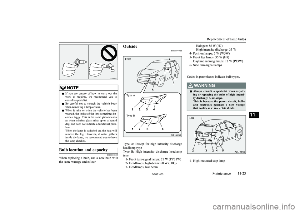
Outside
E01003304055
Type A: Except for high intensity discharge
headlamp type
Type B: High intensity discharge headlamp type 1- Front turn-signal lamps: 21 W (PY21W)
2- Headlamps, high-beam: 60 W (HB3) 3- Headlamps, low beam
Halogen: 55 W (H7)
High intensity discharge: 35 W
4- Position lamps: 5 W (W5W)
5- Front fog lamps: 35 W (H8) Daytime running lamps: 13 W (P13W)
6- Side turn-signal lamps
Codes in parentheses indicate bulb types.WARNINGl Always consult a specialist when repair-
ing or replacing the bulbs of high intensi- ty discharge headlamps.
This is because the power circuit, bulbs and electrodes generate a high voltage
that could cause an electric shock.
1- High-mounted stop lamp
Replacement of lamp bulbs
11-23OGGE14E5Maintenance11 FrontType A
Type B Rear
Page 400 of 442
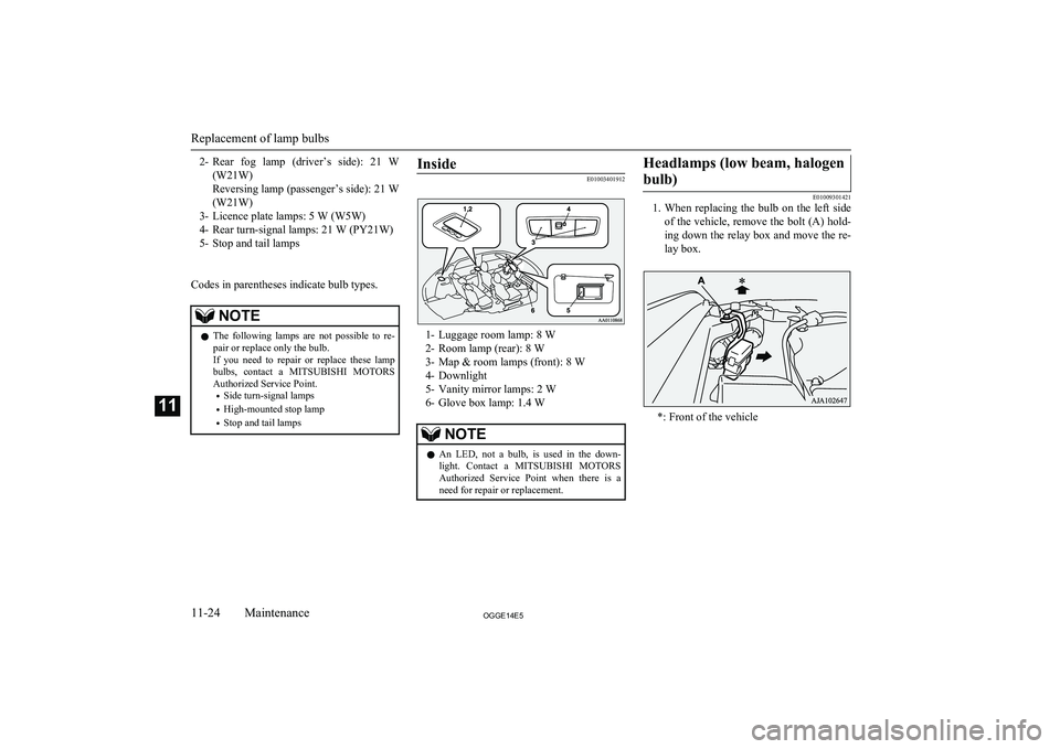
2-Rear fog lamp (driver’s side): 21 W
(W21W)
Reversing lamp (passenger’s side): 21 W (W21W)
3- Licence plate lamps: 5 W (W5W) 4- Rear turn-signal lamps: 21 W (PY21W)
5- Stop and tail lamps
Codes in parentheses indicate bulb types.NOTEl The following lamps are not possible to re-
pair or replace only the bulb.
If you need to repair or replace these lamp
bulbs, contact a MITSUBISHI MOTORS
Authorized Service Point.
• Side turn-signal lamps
• High-mounted stop lamp
• Stop and tail lampsInside
E01003401912
1- Luggage room lamp: 8 W
2- Room lamp (rear): 8 W
3- Map & room lamps (front): 8 W
4- Downlight
5- Vanity mirror lamps: 2 W
6- Glove box lamp: 1.4 W
NOTEl An LED, not a bulb, is used in the down-
light. Contact a MITSUBISHI MOTORS
Authorized Service Point when there is a
need for repair or replacement.Headlamps (low beam, halogen
bulb)
E01009301421
1. When replacing the bulb on the left side
of the vehicle, remove the bolt (A) hold-ing down the relay box and move the re-
lay box.
*: Front of the vehicle
Replacement of lamp bulbs
11-24OGGE14E5Maintenance11
Page 403 of 442
Front turn-signal lamps
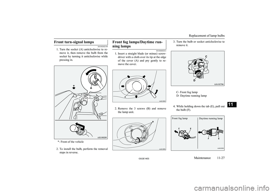
E01003802199
1. Turn the socket (A) anticlockwise to re-
move it, then remove the bulb from the socket by turning it anticlockwise whilepressing in.
*: Front of the vehicle
2. To install the bulb, perform the removal
steps in reverse.
Front fog lamps/Daytime run-
ning lamps
E01004002811
1. Insert a straight blade (or minus) screw-
driver with a cloth over its tip at the edge
of the cover (A) and pry gently to re-
move the cover.
2. Remove the 3 screws (B) and remove
the lamp unit.
3. Turn the bulb or socket anticlockwise to
remove it.
C- Front fog lamp
D- Daytime running lamp
4. While holding down the tab (E), pull out
the bulb (F).
Replacement of lamp bulbs
11-27OGGE14E5Maintenance11 Daytime running lampFront fog lamp
Page 405 of 442
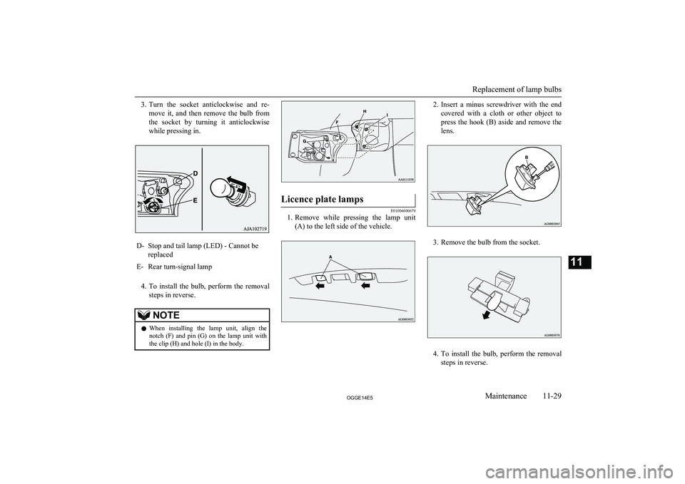
3.Turn the socket anticlockwise and re-
move it, and then remove the bulb from the socket by turning it anticlockwise
while pressing in.D-Stop and tail lamp (LED) - Cannot be
replacedE-Rear turn-signal lamp
4. To install the bulb, perform the removal
steps in reverse.
NOTEl When installing the lamp unit, align the
notch (F) and pin (G) on the lamp unit with the clip (H) and hole (I) in the body.Licence plate lamps
E01004600679
1. Remove while pressing the lamp unit
(A) to the left side of the vehicle.
2. Insert a minus screwdriver with the end
covered with a cloth or other object to press the hook (B) aside and remove the lens.
3. Remove the bulb from the socket.
4. To install the bulb, perform the removal
steps in reverse.
Replacement of lamp bulbs
11-29OGGE14E5Maintenance11
Page 422 of 442
Electric tailgate..................................................4-20
Electric window control.................................... 4-33
Electrical Parking switch...................................7-14
Electronic immobilizer (Anti-theft starting system)................................................ 4-03
Emergency starting............................................9-02
Emergency stop signal system.......................... 7-27
Engine specifications.......................................12-06
Engine Coolant..............................................11-06,12-10
Number....................................................... 12-03
Oil............................................................... 11-05
Oil and oil filter........................................... 12-10
Overheating................................................... 9-04
Specifications.............................................. 12-06
Used engine oils safety instructions and disposal information............................. 2-15
Exterior and interior lamp operation............... 11-15
F
Fluid capacities and lubricants........................ 12-10
Fluid Automatic transmission fluid...................... 12-10
Brake fluid........................................ 11-08,12-10
Clutch fluid................................................. 12-10
CVT fluid.................................................... 12-10
Engine coolant.................................. 11-06,12-10
Plug-in hybrid EV system coolant.............. 11-06
Washer fluid..................................... 11-08,12-10
Forward Collision Mitigation System (FCM)... 7-55
Front fog lamp indication lamp......................... 6-42
Front fog lamps Bulb capacity.............................................. 11-23
Replacement................................................ 11-27
Switch........................................................... 6-52
Front room lamp................................................ 8-72
Bulb capacity.............................................. 11-24
Front seats......................................................... 5-03
Front turn-signal lamps Bulb capacity.............................................. 11-23
Replacement................................................ 11-27
Fuel consumption............................................ 12-09
Fuel Filling the fuel tank....................................... 2-12Fuel selection................................................ 2-12Modification/alterations to the electrical systems......................................... 2-14
Tank capacity................................................ 2-13
Fuses................................................................ 11-16
Fusible links.................................................... 11-16
G
General maintenance....................................... 11-15
General vehicle data........................................ 12-04
Genuine parts.....................................................2-15
Glove box lamp Bulb capacity.............................................. 11-24
H
Hazard warning flasher switch.......................... 6-50
Hazard warning indication lamps......................6-41
Head restraints................................................... 5-05
Headlamp levelling switch................................ 6-49
Headlamp washer switch...................................6-58
Headlamps Bulb capacity.............................................. 11-23
Headlamp flasher.......................................... 6-47Replacement..................................... 11-24,11-25Switch........................................................... 6-45
Heated mirror.................................................... 7-08
Heated seats....................................................... 5-04
Heating.............................................................. 8-14
High-mounted stop lamp................................. 11-23
Hill start assist................................................... 7-26
Hinges and latches lubrication........................ 11-16
Horn switch....................................................... 6-60
I
If the vehicle breaks down................................ 9-02
Indication lamps................................................ 6-41
Information screen display................................ 6-44
Inside rear-view mirror......................................7-05
Inside tailgate release........................................ 4-26
Inspection and maintenance following rough road operation........................................ 7-20
Instruments........................................................ 6-02
Interior lamps.................................................... 8-72
J
Jack.................................................................... 9-06Storage.......................................................... 9-06
Jump starting (Emergency starting).................. 9-02
K
Keyless entry system......................................... 4-03
Keyless operation system.................................. 4-06
Alphabetical index
13- 2 OGGE14E5Alphabetical index