maintenance MITSUBISHI OUTLANDER PHEV 2014 Owner's Manual (in English)
[x] Cancel search | Manufacturer: MITSUBISHI, Model Year: 2014, Model line: OUTLANDER PHEV, Model: MITSUBISHI OUTLANDER PHEV 2014Pages: 442, PDF Size: 19.04 MB
Page 2 of 442
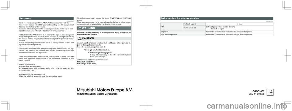
ForewordE09200105969
Thank you for selecting an OUTLANDER PHEV as your new vehicle.
This owner’s manual will add to your understanding and full enjoyment of
the many fine features of this vehicle.
It contains information prepared to acquaint you with the proper way to oper-
ate and maintain your vehicle for the utmost in driving pleasure.
MITSUBISHI MOTORS Europe B.V. reserves the right to make changes in
design and specifications and/or to make additions to or improvements in
this product without obligation to install them on products previously manu- factured.
It is an absolute requirement for the driver to strictly observe all laws and
regulations concerning vehicles.
This owner’s manual has been written in compliance with such laws and reg- ulations, but some of the contents may become contradictory with later amendment of the laws and regulations.
Please leave this owner’s manual in this vehicle at time of resale. The next
owner will appreciate having access to the information contained in this
owner’s manual.
Repairs to your vehicle:
Vehicles in the warranty period:
All warranty repairs must be carried out by a MITSUBISHI MOTORS Au-
thorized Service Point.
Vehicles outside the warranty period:
Where the vehicle is repaired is at the discretion of the owner.
Throughout this owner’s manual the words WARNING and CAUTION
appear.
These serve as reminders to be especially careful. Failure to follow instruc-
tions could result in personal injury or damage to your vehicle.WARNING
indicates a strong possibility of severe personal injury or death if in- structions are not followed.
CAUTION
means hazards or unsafe practices that could cause minor personal in-
jury or damage to your vehicle.
You will see another important symbol:
NOTE:gives helpful information.*:indicates optional equipment.
It may differ according to the sales classification; refer to the sales catalogue.
Abbreviations used in this owner’s manual:
LHD: Left-Hand Drive
RHD: Right-Hand Drive
Information for station service
E09300103852Fuel
Fuel tank capacity45 litresFuel requirementsUnleaded petrol octane number (EN228)95 RON or higherEngine oilRefer to the “Maintenance” section for the selection of engine oil.Tyre inflation pressureRefer to the “Maintenance” section for the tyre inflation pressure.
© 2013 Mitsubishi Motors Corporation
14
OGGE14E5
BLC-14-000978
Page 3 of 442
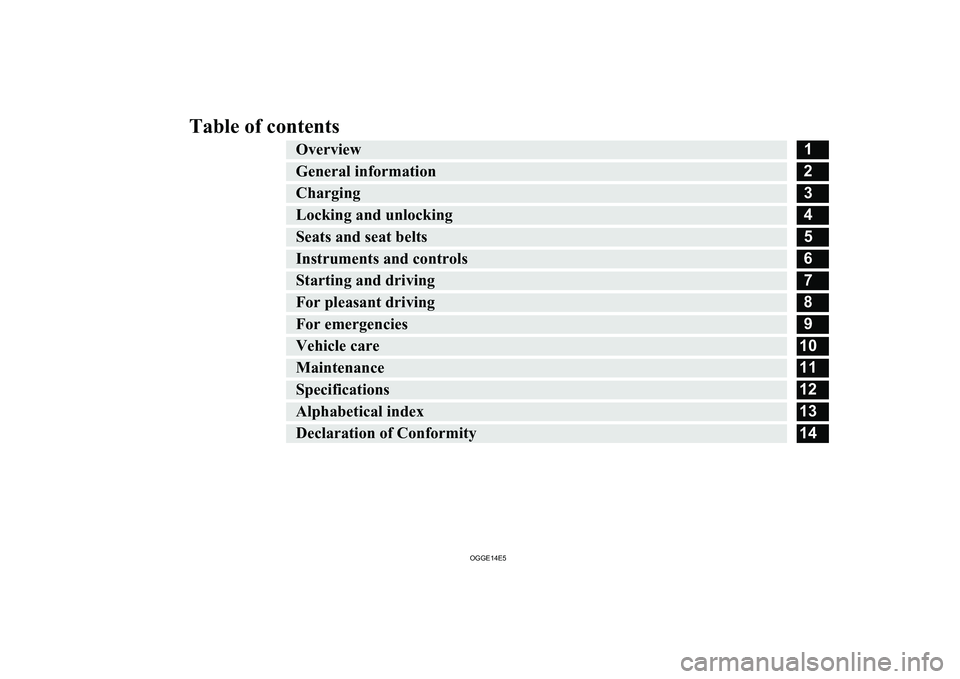
Table of contentsOverview1General information2Charging3Locking and unlocking4Seats and seat belts5Instruments and controls6Starting and driving7For pleasant driving8For emergencies9Vehicle care10Maintenance11Specifications12Alphabetical index13Declaration of Conformity14
OGGE14E5
Page 21 of 442
NOTE•Certain front, side or rear collisions.
• Certain Plug-in Hybrid EV system mal-
functions.
l When the emergency shut-off system is acti-
vated, the ready indicator is turned off. Refer
to “Indication and warning lamps” on page 6-23.
l If the emergency shut-off system activates,
contact a MITSUBISHI MOTORS Author-
ized Service Point.Inspection and maintenance
E00204300033
When performing inspection and mainte-
nance, be careful in the following points.
WARNINGl Before performing inspection or mainte-
nance, be sure to disconnect the charge connector from the vehicle and confirmthat put the operation mode of the power
switch in “OFF”.WARNINGl Never touch, disassemble, remove or re-
place highvoltage parts, exposed electrical
components, cables or connectors. Failure
to follow this instruction can result in se- vere burns or electric shock causing seri-ous injury or death. High-voltage cables are colored orange. The vehicle high volt-
age system has no user serviceable parts. Take your vehicle to a MITSUBISHI
MOTORS Authorized Service Point for
any necessary maintenance.
l Never touch the service plug under the
rear seat. Improper handling of this could
cause an electric shock which result in a
serious injury or death. The service plug
is used to shut off the high voltage from the drive battery when repairing the vehi-
cle at a MITSUBISHI MOTORS Author-
ized Service Point.
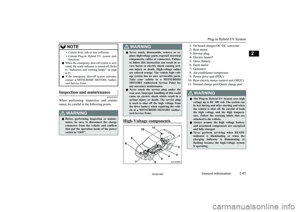
High-Voltage components
1- On board charger/DC-DC converter
2- Rear motor
3- Service plug
4- Electric heater*
5- Drive Battery
6- Front motor
7- Generator
8- Air conditioner compressor
9- Power drive unit (PDU)
10- Rear electric motor control unit (MUC) 11- Normal charge port/Quick charge portWARNINGl The Plug-in Hybrid EV System uses high
voltage up to DC 300 volt. The system can
be hot during and after starting and when the vehicle is shut off. Be careful of both the high voltage and the high tempera-
ture. Follow the warning labels that are
attached to the vehicle.
l Always assume the high voltage battery
and associated components are energized and fully charged.
l Never perform servicing when READY
indicator is illuminating or when the charging indicator is illuminating orflashing because the high-voltage system
is operating.
Plug-in Hybrid EV System
2-07OGGE14E5General information2
Page 130 of 442
If there is a problem involving one or more of
the SRS components, the warning lamp will come on and stay on. At the same time, the
warning display will appear on the informa- tion screen in the multi information display.
The SRS warning lamp/display is shared by
the SRS airbag and the seat belt pretensioner system.WARNINGl If any of the following conditions occur,
there may be a problem with the SRS air- bags and/or seat belt pretensioners, and they may not function properly in a colli-
sion or may suddenly activate without a
collision:
• Even when the operation mode is in
ON, the SRS warning lamp does notcome on or it remains on.
• The SRS warning lamp and/or the
warning display comes on while driv- ing.
The SRS airbags and seat belt pretension- ers are designed to help reduce the risk of
serious injury or death in certain colli- sions. If either of the above conditions oc-
curs, immediately have your vehicle checked by a MITSUBISHI MOTORS
Authorized Service Point.SRS servicing
E00407902658
WARNINGl We recommend any maintenance per-
formed on or near the components of the
SRS to be performed by a MITSUBISHI
MOTORS Authorized Service Point.
Improper work on the SRS components or wiring could result in inadvertent de-
ployment of the airbags, or could render
the SRS inoperative; either situation could result in serious injury.
l Do not modify your steering wheel, seat
belt retractor or any other SRS compo-
nents. For example, replacement of the
steering wheel, or modifications to the
front bumper or body structure can ad- versely affect SRS performance and lead
to possible injury.
l If your vehicle has sustained any damage,
we recommend you to have the SRS in- spected to ensure it is in proper workingorder.
l Do not modify your front seats, centre pil-
lar and centre console.
It can adversely affect SRS performance and lead to possible injury.
l If you found any tear, scratch, crack or
damage to the portion where the airbag is
stored, you should have the SRS inspected
by a MITSUBISHI MOTORS Authorized
Service Point.NOTEl If your vehicle has to be scrapped, do this in
line with local legislation and contact a
MITSUBISHI MOTORS Authorized Serv-
ice Point to safely dismantle the airbag sys- tem.
Supplemental restraint system (SRS) - airbag
5-36OGGE14E5Seats and seat belts5
Page 143 of 442
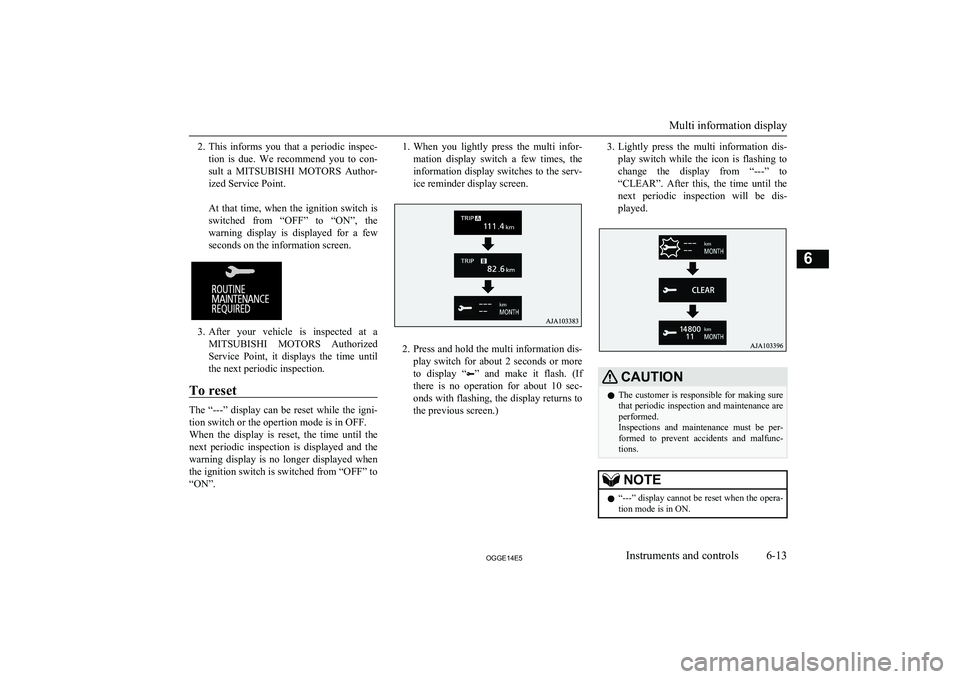
2.This informs you that a periodic inspec-
tion is due. We recommend you to con-
sult a MITSUBISHI MOTORS Author-
ized Service Point.
At that time, when the ignition switch is switched from “OFF” to “ON”, the
warning display is displayed for a few seconds on the information screen.
3. After your vehicle is inspected at a
MITSUBISHI MOTORS Authorized
Service Point, it displays the time until
the next periodic inspection.
To reset
The “---” display can be reset while the igni-
tion switch or the opertion mode is in OFF.
When the display is reset, the time until the
next periodic inspection is displayed and the warning display is no longer displayed when
the ignition switch is switched from “OFF” to
“ON”.
1. When you lightly press the multi infor-
mation display switch a few times, the information display switches to the serv-
ice reminder display screen.
2. Press and hold the multi information dis-
play switch for about 2 seconds or more to display “
” and make it flash. (If
there is no operation for about 10 sec- onds with flashing, the display returns tothe previous screen.)
3. Lightly press the multi information dis-
play switch while the icon is flashing to
change the display from “---” to
“CLEAR”. After this, the time until the
next periodic inspection will be dis- played.CAUTIONl The customer is responsible for making sure
that periodic inspection and maintenance are
performed.
Inspections and maintenance must be per- formed to prevent accidents and malfunc- tions.NOTEl “---” display cannot be reset when the opera-
tion mode is in ON.
Multi information display
6-13OGGE14E5Instruments and controls6
Page 167 of 442
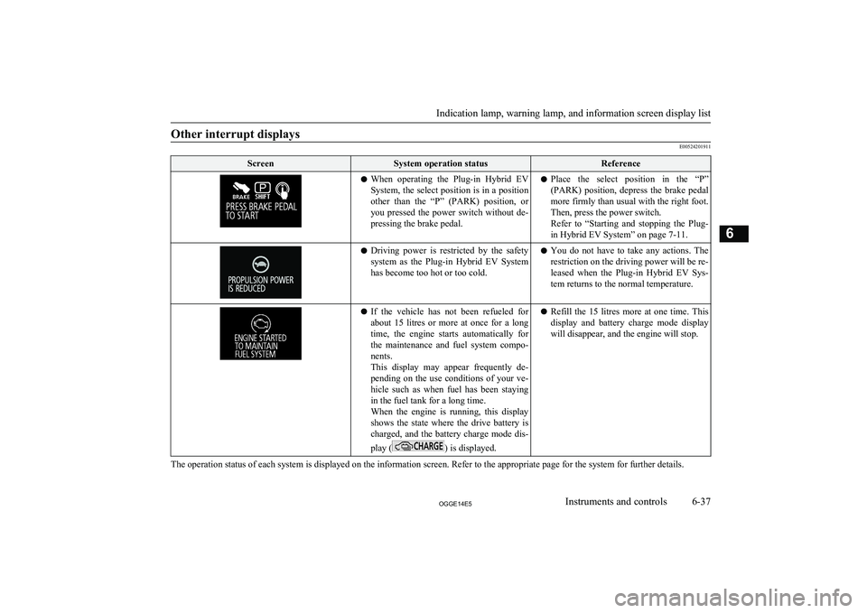
Other interrupt displays
E00524201911
ScreenSystem operation statusReferencelWhen operating the Plug-in Hybrid EV
System, the select position is in a position
other than the “P” (PARK) position, or
you pressed the power switch without de- pressing the brake pedal.l Place the select position in the “P”
(PARK) position, depress the brake pedal
more firmly than usual with the right foot. Then, press the power switch.
Refer to “Starting and stopping the Plug- in Hybrid EV System” on page 7-11.l Driving power is restricted by the safety
system as the Plug-in Hybrid EV System
has become too hot or too cold.l You do not have to take any actions. The
restriction on the driving power will be re- leased when the Plug-in Hybrid EV Sys- tem returns to the normal temperature.l If the vehicle has not been refueled for
about 15 litres or more at once for a long
time, the engine starts automatically for the maintenance and fuel system compo- nents.
This display may appear frequently de-
pending on the use conditions of your ve- hicle such as when fuel has been staying in the fuel tank for a long time.
When the engine is running, this display
shows the state where the drive battery is charged, and the battery charge mode dis-
play (
) is displayed.
l Refill the 15 litres more at one time. This
display and battery charge mode display will disappear, and the engine will stop.
The operation status of each system is displayed on the information screen. Refer to the appropriate page for the system for further details.
Indication lamp, warning lamp, and information screen display list
6-37OGGE14E5Instruments and controls6
Page 191 of 442
Economical driving............................................................................. 7-02
Driving, alcohol and drugs.................................................................. 7-02
Safe driving techniques....................................................................... 7-02
Parking brake...................................................................................... 7-03 Parking................................................................................................ 7-04
Steering wheel height and reach adjustment....................................... 7-05
Inside rear-view mirror....................................................................... 7-05
Outside rear-view mirrors................................................................... 7-06
Power switch....................................................................................... 7-08 Starting and stopping the Plug-in Hybrid EV System........................ 7-11
Selector Lever (Joystick Type)........................................................... 7-12
Select Position indicator......................................................................7-14
Electrical Parking switch.................................................................... 7-14
Regenerative braking level selector (paddle)*.................................... 7-15
S-AWC (Super All Wheel Control).................................................... 7-17
4-wheel drive operation...................................................................... 7-19
Inspection and maintenance following rough road operation............. 7-20
Cautions on handling of 4-wheel drive vehicles................................. 7-20
Battery save switch............................................................................. 7-21
Battery charge switch.......................................................................... 7-22
Acoustic Vehicle Alerting System (AVAS)....................................... 7-23
Braking................................................................................................ 7-24
Hill start assist..................................................................................... 7-26
Brake assist system............................................................................. 7-27
Emergency stop signal system............................................................ 7-27
Anti-lock brake system (ABS)............................................................ 7-28
Electric power steering system (EPS)................................................. 7-30 Active stability control (ASC)............................................................ 7-31Cruise control*.................................................................................... 7-34Speed Limiter*.................................................................................... 7-38
Adaptive Cruise Control System (ACC)*...........................................7-43 Forward Collision Mitigation System (FCM)*...................................7-55Lane Departure Warning (LDW)*...................................................... 7-61
Tyre pressure monitoring system (TPMS).......................................... 7-64 Reversing sensor system*................................................................... 7-69
Rear-view camera*............................................................................. 7-72
Cargo loads......................................................................................... 7-75Trailer towing......................................................................................7-76Starting and driving
OGGE14E57
Page 210 of 442
NOTElDriving on rough roads can be hard on a ve-
hicle. Before you leave paved roads, be sure all scheduled maintenance and service has
been done, and that you have inspected your vehicle. Pay special attention to the condi- tion of the tyres, and check the tyre pres-
sures.
l MITSUBISHI
MOTORS is not responsible
to the operator for any damage or injury caused or liability incurred by improper and
negligent operation of a vehicle. All techni- ques of vehicle operation depend on the skill and experience of the operator and other par-
ticipating parties. Any deviation from the recommended operating instructions above
is at their own risk.
l Note that the stopping distance required of a
4-wheel drive vehicle differs very little from
that of a 2-wheel drive vehicle. When driv-
ing on a snow-covered road or a slippery, muddy surface, make sure that you keep a
sufficient distance between your vehicle and the one ahead of you.
l The driving posture should be more upright;
adjust the seat to a good position for easy
steering and pedal operation. Be sure to wear
the seat belt.
l After driving on rough roads, check each
part of the vehicle and wash it thoroughlywith water. Refer to the “Inspection andmaintenance following rough road opera-
tion” section and “Maintenance” section.Climbing/descending sharp
grades
Your vehicle may not provide sufficient hill
climbing ability and regenerative brake on steep slope. Avoid driving on steep slopes
even though the vehicle is a 4-wheel drive vehicle.
Inspection and maintenance
following rough roadoperation E00606701407
After operating the vehicle in rough road
conditions, be sure to perform the following inspection and maintenance procedures:
l Check that the vehicle has not been dam-
aged by rocks, gravel, etc.
l Carefully wash the vehicle with water.
Drive the vehicle slowly while lightly
depressing the brake pedal in order to dry out the brakes. If the brakes still do
not function properly, we recommend you to have the brakes checked as soon
as possible.
l Remove the insects, dried grass, etc.
clogging the radiator core.
l Check the inside of the vehicle. If water
entry is found, dry the carpet etc.
l Inspect the headlamps. If the headlamp
bulb is flooded with water, we recom-
mend you to have it drained.Cautions on handling of 4-
wheel drive vehicles E00606801844
Tyres and wheels
Since the driving torque can be applied to the
4 wheels, the driving performance of the ve- hicle when operating in 4-wheel drive is
greatly affected by the condition of the tyres.
Pay close attention to the tyres.
l Install only the specified tyres on all
wheels. Refer to “Tyres and wheels” on page 12-08.
l Be sure all 4 tyres and wheels are the
same size and type.
When it is necessary to replace any of
the tyres or wheels, replace all 4 tyres.
l All tyres should be rotated before the
wear difference between the front and
rear tyres is recognizable.
Good vehicle performance cannot be expec- ted if there is a difference in wear between tyres. Refer to “Tyre rotation” on page 11-11.
Inspection and maintenance following rough road operation
7-20OGGE14E5Starting and driving7
Page 256 of 442
Under-inflation also reduces fuel efficiencyand tyre tread life, and may affect the vehi-
cle’s handling and stopping ability.
Please note that the tyre pressure monitoring system (TPMS) is not a substitute for proper
tyre maintenance, and it is the driver’s re- sponsibility to maintain correct tyre pressure,even if under-inflation has not reached thelevel to trigger illumination of the tyre pres-
sure monitoring system (TPMS) low tyre
pressure telltale.
Your vehicle has also been equipped with a warning lamp to indicate when the system is
not operating properly.
The warning lamp is combined with the low
tyre pressure telltale.
When the system detects a malfunction, the
telltale will flash for approximately one mi- nute and then remain continuously illumina- ted. This sequence will continue upon subse-
quent vehicle start-ups as long as the mal-
function exists.
When the warning lamp is illuminated, the system may not be able to detect or signal
low tyre pressure as intended.The tyre pressure monitoring system (TPMS)
malfunctions may occur for a variety of rea-
sons, including the installation of replace- ment or alternate tyres or wheels on the vehi-cle that prevent the tyre pressure monitoring
system (TPMS) from functioning properly. Always check the tyre pressure monitoringsystem (TPMS) malfunction telltale after re-
placing one or more tyres or wheels on your vehicle to ensure that the replacement or al- ternate tyres and wheels allow the tyre pres-
sure monitoring system (TPMS) to continue to function properly.If the warning lamp/display il-
luminates while driving
E00637300079
1. If the warning lamp illuminates, avoid
hard braking, sharp steering manoeuvres
and high speeds. You should stop and adjust the tyres to the proper inflationpressure as soon as possible. Adjust the spare tyre at the same time. Refer to
“Tyres” on page 11-10.
NOTEl In addition, the warning display will be dis-
played on the information screen in the mul-
ti-information display.
l When inspecting or adjusting the tyre pres-
sure, do not apply excessive force to the
valve stem to avoid breakage.NOTEl After inspecting or adjusting the tyre pres-
sure, always reinstall the valve cap on the
valve stem.
Without the valve cap, dirt or moisture could
get into the valve, resulting in damage to the tyre inflation pressure sensor.
l Do not use metal valve caps, which may
cause a metal reaction, resulting in corrosion and damage of the tyre inflation pressure
sensors.
l Once adjustments have been made, the
warning lamp will go off after a few minutesof driving.
2. If the warning lamp remains illuminated
after you have been driving for about 10
minutes after you adjust the tyre infla- tion pressure, one or more of the tyresmay have a puncture. Inspect the tyreand if it has a puncture, have it repaired
by a MITSUBISHI MOTORS Author-
ized Service Point as soon as possible.
WARNINGl If the warning lamp/display illuminates
while you are driving, avoid hard brak- ing, sharp steering manoeuvres and high speeds.
Driving with an under-inflated tyre ad-
versely affects vehicle performance and
can result in an accident.
Tyre pressure monitoring system (TPMS)
7-66OGGE14E5Starting and driving7
Page 281 of 442
Important operation tips forthe air conditioner E00708302098
l Park the vehicle in the shade.
Parking in the hot sun will make the ve-
hicle inside extremely hot, and it will re-
quire more time to cool the interior.
If it is necessary to park in the sun, open
the windows for the first few minutes of air conditioning operation to expel the
hot air.
l Close the windows when the air condi-
tioner is in use. The entry of outside air
through open windows will reduce the cooling efficiency.
l Too much cooling is not good for the
health. Keep the difference between the
vehicle interior temperature and outside
temperature to 5 to 6 °C.
l When operating the system, make sure
the air intake, which is located in front of the windscreen, is free of obstructionssuch as leaves and snow. Leaves collec-
ted in the air-intake plenum may reduce
air flow and plug the plenum water drains.
l Too much cooling/heating can affect the
EV cruising range, so maintain an appro-
priate temperature to extend the EV
cruising range.Air conditioning system refrig-
erant and lubricant recommen-dations
If the air conditioner seems less effective than usual, the cause might be a refrigerant leak. We recommend you to have the system
inspected.
The air conditioning system in your vehicle must be charged with the refrigerant
HFC-134a and the lubricant POE MA68EV.
Use of any other refrigerant or lubricant will cause severe damage which will result in the
need to replace your vehicle’s entire air con- ditioning system. The release of refrigerantinto the atmosphere is not recommended.
The new refrigerant HFC-134a in your vehi-
cle will not harm the ozone layer.
We recommend you to recover and recycle the refrigerant for reuse.
During a long period of disuse
The air conditioner should be operated for atleast five minutes each week, even in cold
weather. This is to prevent the compressor from seizing and to maintain the air condi-
tioner in the best operating condition.
Air purifier
E00708400718
An air filter has been incorporated into this air conditioner so that dirt and dust are
cleaned from the air.
Replace the air filter periodically as its ability
to clean the air will be reduced as it collects pollen and dirt. For the maintenance interval,
refer to the “SERVICE BOOKLET”.NOTEl Operation in certain conditions such as driv-
ing on a dusty road and frequent use of the air conditioner can lead to reduction of serv-
ice life of the filter. When you feel that the air flow is lower than normal or when the
windscreen or windows start to fog up easi- ly, replace the air filter.
We recommend you to have it checked.Remote Climate Control
E00735401045
You can run the air conditioner in advance ofusing the vehicle.
For details, refer to “Remote Climate Con- trol” on page 3-23.
Important operation tips for the air conditioner
8-13OGGE14E5For pleasant driving8