wheel size MITSUBISHI OUTLANDER PHEV 2014 Owner's Manual (in English)
[x] Cancel search | Manufacturer: MITSUBISHI, Model Year: 2014, Model line: OUTLANDER PHEV, Model: MITSUBISHI OUTLANDER PHEV 2014Pages: 442, PDF Size: 19.04 MB
Page 14 of 442
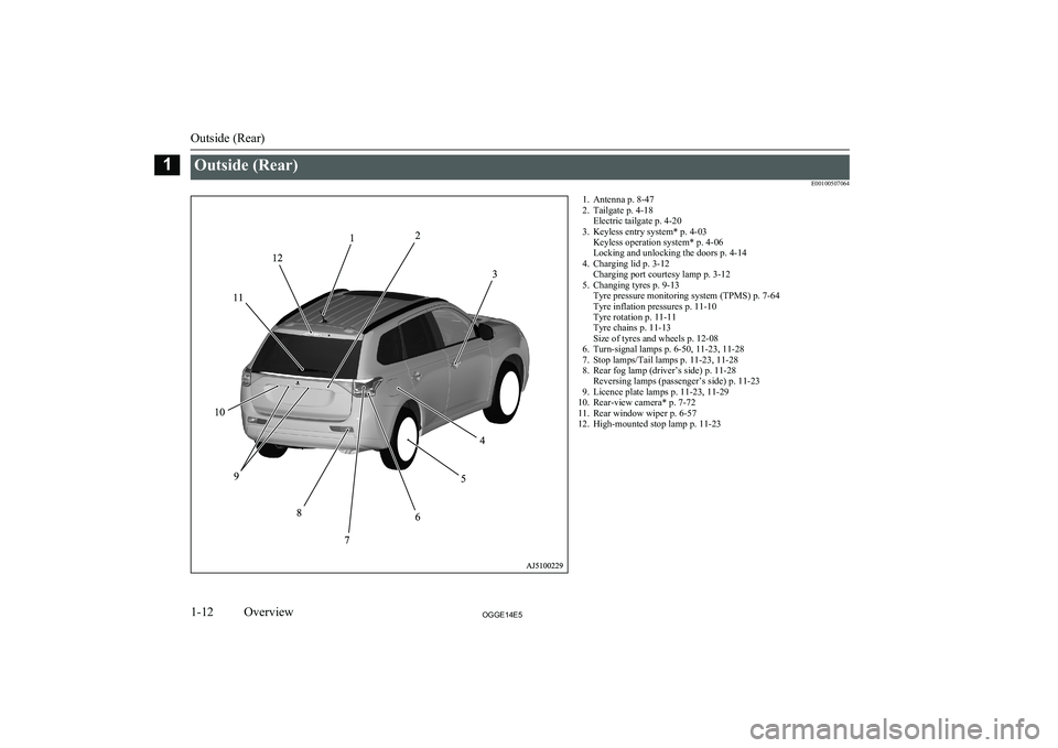
Outside (Rear)E001005070641. Antenna p. 8-472. Tailgate p. 4-18 Electric tailgate p. 4-20
3. Keyless entry system* p. 4-03 Keyless operation system* p. 4-06
Locking and unlocking the doors p. 4-14
4. Charging lid p. 3-12 Charging port courtesy lamp p. 3-12
5. Changing tyres p. 9-13 Tyre pressure monitoring system (TPMS) p. 7-64
Tyre inflation pressures p. 11-10
Tyre rotation p. 11-11
Tyre chains p. 11-13
Size of tyres and wheels p. 12-08
6. Turn-signal lamps p. 6-50, 11-23, 11-28
7. Stop lamps/Tail lamps p. 11-23, 11-28
8. Rear fog lamp (driver’s side) p. 11-28 Reversing lamps (passenger’s side) p. 11-23
9. Licence plate lamps p. 11-23, 11-29
10. Rear-view camera* p. 7-72
11. Rear window wiper p. 6-57
12. High-mounted stop lamp p. 11-23
Outside (Rear)
1-12OGGE14E5Overview1
Page 28 of 442
5.When the gun stops automatically, do
not fill with fuel any more.
6. To close, turn the fuel cap slowly clock-
wise until you hear clicking sounds, then
gently push the fuel tank filler door
closed.Installation of accessories
E00200300963
We recommend you to consult aMITSUBISHI MOTORS Authorized Service
Point.
l The installation of accessories, optional
parts, etc., should only be carried out
within the limits prescribed by law in your country, and in accordance with the
guidelines and warnings contained with-
in the documents accompanying this ve- hicle.
l Installing electric components incorrect-
ly could lead to a fire. Please refer to Modification/alteration to the electrical
or fuel systems section within this own- er’s manual.
l Using a cellular phone or radio set inside
the vehicle without an external antenna
may cause electrical system interference,
which could lead to unsafe vehicle oper- ation.
l Tyres and wheels which do not meet
specifications must not be used.
Refer to the “Specifications” section for information regarding wheel and tyre
sizes.
Important points!
Due to large number of accessory and re- placement parts of different manufactures
available in the market, it is not possible, not only for MITSUBISHI MOTORS , but also
for a MITSUBISHI MOTORS Authorized
Service Point, to check whether the attach- ment or installation of such parts affects theoverall safety of your MITSUBISHI-vehicle.
Even when such parts are officially author-
ized, for example by a “general operators permit” (an appraisal for the part) or throughthe execution of the part in an officially ap-
proved manner of construction, or when a single operation permit following the attach-
ment or installation of such parts, it cannot be deduced from that alone, that the driving
safety of your vehicle has not been affected.
Consider also that there basically exists no li-
ability on the part of the appraiser or the offi- cial. Maximum safety can only be ensured
with parts recommended, sold and fitted or
installed by a MITSUBISHI MOTORS au-
thorized Service Point ( MITSUBISHI
MOTORS GENUINE replacement parts and
MITSUBISHI MOTORS accessories). The
same also pertains to modifications of
MITSUBISHI vehicles with respect to the
production specifications. For safety reasons,
do not attempt any modifications other than those that follow the recommendations of a
MITSUBISHI MOTORS authorized Service
Point.Modification/alterations to
the electrical or fuel systems E00200400368
MITSUBISHI MOTORS CORPORATION
has always manufactured safe, high quality vehicles. In order to maintain this safety and
quality, it is important that any accessory that
is to be fitted, or any modifications carried
out which involve the electrical or fuel sys- tems, should be carried out in accordancewith MITSUBISHI guidelines.
Installation of accessories
2-14OGGE14E5General information2
Page 208 of 442
CAUTIONlControl of the braking force does not en-
hance the stopping performance of the vehi-
cle, therefore, pay careful attention to the safety of your surroundings when driving.
Left-right differential limiting
function
The left-right differential limiting function is
a function that enhances driving performance and vehicle stability by preventing idle spin-
ning of a wheel when driving on a slippery road or when the road surfaces of left andright wheels are different.
Yaw control function
The yaw control function is a function thatenhances vehicle cornering performance and vehicle stability with management of vehicle
turning power (yaw moment) by controlling the brake force when the vehicle does not
turn in response to steering input, such as
when the steering wheel is turned quickly or when driving on a slippery road.
4WD lock switch
E00637000021
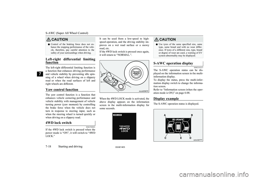
If the 4WD lock switch is pressed when the
power mode is “ON”, it will switch to “4WD LOCK.”
It can be used from a low-speed to high-
speed operation, and the driving stability im- proves on a wet road surface or a snowyroad, etc.
If the 4WD lock switch is pressed once again, it will return to “NORMAL.”.
When the 4WD LOCK mode is activated, the
above display appears on the information
screen in the multi-information display for some seconds.
CAUTIONl Use tyres of the same specified size, same
type, same brand and with no wear differ- ence. If tyres of a different size, type, brandor degree of wear are used, a warning of EVsystem abnormality may be displayed.S-AWC operation display
E00623101217
The S-AWC operation status can be dis-
played on the information screen in the multi-
information display.
To display the status, press the multi-infor-
mation display switch to change the informa- tion screen.
Refer to “Information screen (when the oper- ation mode is ON)” on page 6-08.
Display example
The S-AWC operation status is displayed.
S-AWC (Super All Wheel Control)
7-18OGGE14E5Starting and driving7
Page 210 of 442
NOTElDriving on rough roads can be hard on a ve-
hicle. Before you leave paved roads, be sure all scheduled maintenance and service has
been done, and that you have inspected your vehicle. Pay special attention to the condi- tion of the tyres, and check the tyre pres-
sures.
l MITSUBISHI
MOTORS is not responsible
to the operator for any damage or injury caused or liability incurred by improper and
negligent operation of a vehicle. All techni- ques of vehicle operation depend on the skill and experience of the operator and other par-
ticipating parties. Any deviation from the recommended operating instructions above
is at their own risk.
l Note that the stopping distance required of a
4-wheel drive vehicle differs very little from
that of a 2-wheel drive vehicle. When driv-
ing on a snow-covered road or a slippery, muddy surface, make sure that you keep a
sufficient distance between your vehicle and the one ahead of you.
l The driving posture should be more upright;
adjust the seat to a good position for easy
steering and pedal operation. Be sure to wear
the seat belt.
l After driving on rough roads, check each
part of the vehicle and wash it thoroughlywith water. Refer to the “Inspection andmaintenance following rough road opera-
tion” section and “Maintenance” section.Climbing/descending sharp
grades
Your vehicle may not provide sufficient hill
climbing ability and regenerative brake on steep slope. Avoid driving on steep slopes
even though the vehicle is a 4-wheel drive vehicle.
Inspection and maintenance
following rough roadoperation E00606701407
After operating the vehicle in rough road
conditions, be sure to perform the following inspection and maintenance procedures:
l Check that the vehicle has not been dam-
aged by rocks, gravel, etc.
l Carefully wash the vehicle with water.
Drive the vehicle slowly while lightly
depressing the brake pedal in order to dry out the brakes. If the brakes still do
not function properly, we recommend you to have the brakes checked as soon
as possible.
l Remove the insects, dried grass, etc.
clogging the radiator core.
l Check the inside of the vehicle. If water
entry is found, dry the carpet etc.
l Inspect the headlamps. If the headlamp
bulb is flooded with water, we recom-
mend you to have it drained.Cautions on handling of 4-
wheel drive vehicles E00606801844
Tyres and wheels
Since the driving torque can be applied to the
4 wheels, the driving performance of the ve- hicle when operating in 4-wheel drive is
greatly affected by the condition of the tyres.
Pay close attention to the tyres.
l Install only the specified tyres on all
wheels. Refer to “Tyres and wheels” on page 12-08.
l Be sure all 4 tyres and wheels are the
same size and type.
When it is necessary to replace any of
the tyres or wheels, replace all 4 tyres.
l All tyres should be rotated before the
wear difference between the front and
rear tyres is recognizable.
Good vehicle performance cannot be expec- ted if there is a difference in wear between tyres. Refer to “Tyre rotation” on page 11-11.
Inspection and maintenance following rough road operation
7-20OGGE14E5Starting and driving7
Page 211 of 442
lCheck the tyre inflation pressure regular-
ly.CAUTIONl Always use tyres of the same size, same
type, and same brand, and which have no
wear differences. Using tyres of different size, type, brands or degree of wear, will in-
crease the differential oil temperature, result-
ing in possible damage to the driving sys- tem. Further, the drive train will be subjec-
ted to excessive loading possibly leading to oil leakage, component seizure, or other seri-ous faults.
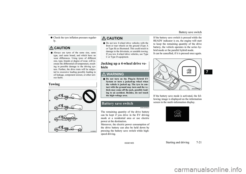
Towing
CAUTIONl Do not tow 4-wheel drive vehicles with the
front or rear wheels on the ground (Type Aor Type B) as illustrated. This could result in
damage to the drivetrain, or unstable towing. If you tow 4-wheel drive vehicles, use Type
C or Type D equipment.
Jacking up a 4-wheel drive ve-
hicle
WARNINGl Do not turn on the Plug-in Hybrid EV
System or turn a jacked-up wheel whenthe vehicle is jacked up. The tyre in con-
tact with the ground may turn and the ve- hicle may come off the jack, possibly lead-
ing to an accident. Besides, do not touch
the high-voltage area.Battery save switch
E00636800022
The remaining quantity of the drive battery
can be kept if you drive in the EV driving mode at a residential area or use electric
power at the destination.
Moreover, the electric power consumption of
the drive battery can also be held down by
pressing the battery save switch while high- speed driving.
If the battery save switch is pressed while the
READY indicator is on, the engine will start
to keep the remaining quantity of the drive battery, the vehicle operates in the series hy-
brid mode or the parallel hybrid mode.
It can be cancelled, if it is pressed once again.
If the battery save mode is activated, the fol-
lowing image is displayed on the information screen in the multi-information display.
Battery save switch
7-21OGGE14E5Starting and driving7
Page 219 of 442
lYou will hear the operation sound of the
motor coming from the Plug-in Hybrid
EV System compartment immediately following start off after starting the
Plug-in Hybrid EV System. If the brake
pedal is depressed at that moment, you can feel the brake pedal pulsating.
This pulsation is due to the self-diagno-
sis operation of the ABS and does not
indicate a malfunction.
l The ABS will operate after the vehicle
has accelerated to a speed in excess ofapproximately 10 km/h (6 mph). It stops
operating when the vehicle decelerates
to a speed below about 5 km/h (3 mph).CAUTIONl Even the ABS cannot prevent the natural
laws of physics from acting on the vehicle. Itcannot for instance avoid accidents that may
result from excessive speed on bends or fol- lowing another vehicle too closely or aqua- planing. It should remain the driver’s task to
observe safety precautions to judge speeds and brake applications correctly in such con-
ditions.
l Be sure to use tyres of the same type and
size on 4 wheels.
If tyre types or sizes are mixed, ABS may not function normally.CAUTIONl Never install a limited-slip differential,
which is not MITSUBISHI MOTORS GEN-
UINE parts, as the ABS may not function
normally.
We recommend you to consult a
MITSUBISHI MOTORS Authorized Serv-
ice Point.ABS warning lamp/display
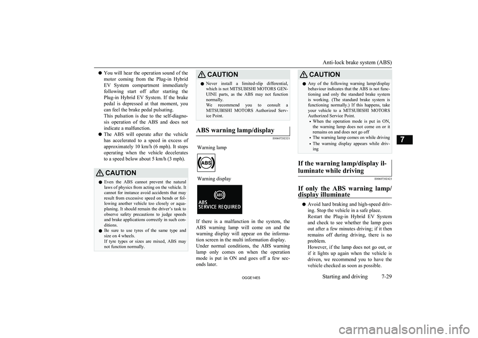
E00607202321
Warning lampWarning display
If there is a malfunction in the system, the
ABS warning lamp will come on and the
warning display will appear on the informa- tion screen in the multi information display.
Under normal conditions, the ABS warning
lamp only comes on when the operation
mode is put in ON and goes off a few sec- onds later.
CAUTIONl Any of the following warning lamp/display
behaviour indicates that the ABS is not func-tioning and only the standard brake system
is working. (The standard brake system is functioning normally.) If this happens, takeyour vehicle to a MITSUBISHI MOTORS
Authorized Service Point.
• When the operation mode is put in ON,
the warning lamp does not come on or it remains on and does not go off
• The warning lamp comes on while driving
• The warning display appears while driv-
ingIf the warning lamp/display il-
luminate while driving
E00607302423
If only the ABS warning lamp/ display illuminate
l Avoid hard braking and high-speed driv-
ing. Stop the vehicle in a safe place.
Restart the Plug-in Hybrid EV System
and check to see whether the lamp goes
out after a few minutes driving; if it then remains off during driving, there is no
problem.
However, if the lamp does not go out, or if it lights up again when the vehicle is driven, we recommend you to have the
vehicle checked as soon as possible.
Anti-lock brake system (ABS)
7-29OGGE14E5Starting and driving7
Page 221 of 442
The power steering system has mechanical
steering capability in case the power assist is lost. If the power assist is lost for some rea-
son, you will still be able to steer your vehi-
cle, but you will notice it takes much more effort to steer. If this happens, have your ve-hicle inspected at a MITSUBISHI MOTORS
Authorized Service Point.WARNINGl Do not stop the Plug-in Hybrid EV Sys-
tem while the vehicle is moving. Stopping the Plug-in Hybrid EV System would
make the steering wheel extremely hard to turn, possibly resulting in an accident.NOTEl During repeated full-lock turning of the
steering wheel (for example, while you are manoeuvring the vehicle into a parking space), a protection function may be activa-
ted to prevent overheating of the power steering system. This function will make the
steering wheel gradually harder to turn. In
this event, limit your turning of the steering wheel for a while. When the system has
cooled down, the steering action will return to normal.NOTEl If you turn the steering wheel while the vehi-
cle is stationary with the headlamps on, the headlamps may become dim. This behaviour
is not abnormal. The headlamps will return to their original brightness after a shortwhile.
Electric power steering system
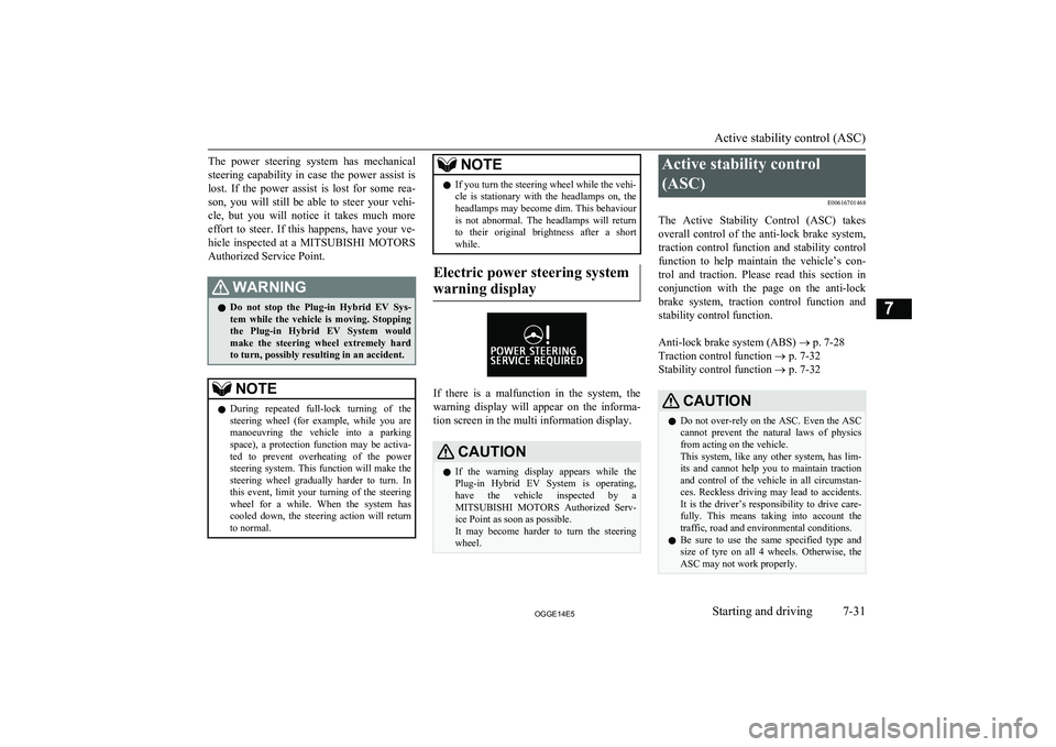
warning display
If there is a malfunction in the system, the warning display will appear on the informa-
tion screen in the multi information display.
CAUTIONl If the warning display appears while the
Plug-in Hybrid EV System is operating,
have the vehicle inspected by a
MITSUBISHI MOTORS Authorized Serv-
ice Point as soon as possible.
It may become harder to turn the steering wheel.Active stability control
(ASC) E00616701468
The Active Stability Control (ASC) takes
overall control of the anti-lock brake system, traction control function and stability control
function to help maintain the vehicle’s con-
trol and traction. Please read this section in conjunction with the page on the anti-lock
brake system, traction control function and stability control function.
Anti-lock brake system (ABS) ® p. 7-28
Traction control function ® p. 7-32
Stability control function ® p. 7-32CAUTIONl Do not over-rely on the ASC. Even the ASC
cannot prevent the natural laws of physics
from acting on the vehicle.
This system, like any other system, has lim-
its and cannot help you to maintain traction and control of the vehicle in all circumstan- ces. Reckless driving may lead to accidents. It is the driver’s responsibility to drive care-
fully. This means taking into account the traffic, road and environmental conditions.
l Be sure to use the same specified type and
size of tyre on all 4 wheels. Otherwise, the ASC may not work properly.
Active stability control (ASC)
7-31OGGE14E5Starting and driving7
Page 249 of 442
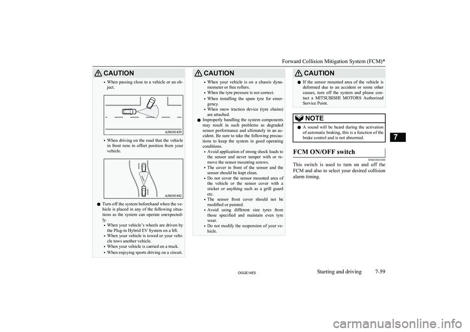
CAUTION•When passing close to a vehicle or an ob-
ject.
• When driving on the road that the vehicle
in front runs in offset position from your
vehicle.
l Turn off the system beforehand when the ve-
hicle is placed in any of the following situa-
tions as the system can operate unexpected- ly.
• When your vehicle’s wheels are driven by
the Plug-in Hybrid EV System on a lift.
• When your vehicle is towed or your vehi-
cle tows another vehicle.
• When your vehicle is carried on a truck.
• When enjoying sports driving on a circuit.
CAUTION•When your vehicle is on a chassis dyna-
mometer or free rollers.
• When the tyre pressure is not correct.
• When installing the spare tyre for emer-
gency.
• When snow traction device (tyre chains)
are attached.
l Improperly handling the system components
may result in such problems as degraded
sensor performance and ultimately in an ac- cident. Be sure to take the following precau-
tions to keep the system in good operating
conditions.
• Avoid application of strong shock loads to
the sensor and never tamper with or re- move the sensor mounting screws.
• The cover in front of the sensor and the
sensor should be kept clean.
• Do not cover the sensor mounted area of
the vehicle or the sensor cover with a
sticker or anything such as a grill guard etc.
• The sensor front cover should not be
modified or painted.
• Avoid using different size tyres from
those specified and maintain even tyre
wear.
• Do not modify the suspension of your ve-
hicle.CAUTIONl If the sensor mounted area of the vehicle is
deformed due to an accident or some other causes, turn off the system and please con-
tact a MITSUBISHI MOTORS Authorized
Service Point.NOTEl A sound will be heard during the activation
of automatic braking, this is a function of the brake control and is not abnormal.FCM ON/OFF switch
E00635601088
This switch is used to turn on and off the
FCM and also to select your desired collision alarm timing.
Forward Collision Mitigation System (FCM)*
7-59OGGE14E5Starting and driving7
Page 348 of 442
If the vehicle breaks downE00800102381
If the vehicle breaks down on the road, move it to the shoulder and use the hazard warning
flashers and/or the warning triangle etc.
Refer to “Hazard warning flasher switch” on page 6-50.
When the vehicle is faulty and will not move,
get help from passengers or bystanders to
push the vehicle and move it to a safe place.
At this time, put the operation mode of the power switch in “ON” and put the select po-sition in “N” (NEUTRAL) position.WARNINGl If you are unable to safely assess the vehi-
cle due to vehicle damage, do not touch
the vehicle. Leave the vehicle and contact emergency services. Advise emergency
responders that this is a Plug-in Hybrid Electric vehicle.
If the ready indicator goes out
while driving
Vehicle operation and control are affected if
the ready indicator goes out while driving.
Before moving the vehicle to a safe area, be aware of the following:
l The brake booster may become inopera-
tive and the pedal effort will increase.
Press down the brake pedal harder than usual.
l The power steering system may not op-
erate, the steering wheel feels heavy when turning it.Emergency starting
E00800503920
If the Plug-in Hybrid EV system cannot be
started because the auxiliary battery is weak or dead, the battery from another vehicle can
be used with jumper cables to start the Plugin
Hybrid EV system.
WARNINGl To start the Plug-in Hybrid EV system us-
ing jumper cables from another vehicle
and perform the correct procedures ac-
cording to the instruction below. Incor- rect procedures could result in a fire, ex-
plosion, electric shock or damage to the
vehicles.
l Keep sparks, cigarettes and flames away
from the battery because the battery may
produce an explosion.CAUTIONl The Plug-in Hybrid EV system cannot be
started by pulling or pushing the vehicle.CAUTIONl Check the other vehicle. It must have a 12-
volt battery. If the other system isn’t 12-volt,shorting can damage both vehicles.
l Use the proper cables suitable for the battery
size to prevent overheating of the cables.
l Check the jumper cables for damage and
corrosion before use.
l Always wear protective eye goggles when
working near the battery.
l Keep the battery out of the reach of children.
l Do not attempt jump starting the auxiliary
battery while the drive battery is being charged. Doing so could damage the charg-
ing equipment or the vehicle.NOTEl If the auxiliary battery is disconnected, the
operation mode of the power switch is mem-
orized. When a booster battery is connected
by jumper cables, the operation mode re- turns to the state before the auxiliary battery
ran down.
Pay due attention if you do not know the op-
eration mode before the auxiliary battery
was fully discharged.
l If the auxiliary battery is fully discharged
with the select position in the “P” (PARK)
position, the select position cannot be changed to other position from the “P”
(PARK) position in some cases. In such a case, the front wheels have been locked.
Therefore, the vehicle cannot be moved.
If the vehicle breaks down
9-02OGGE14E5For emergencies9
Page 363 of 442
CAUTIONlDo not mix one type of tyre with another or
use a different size from the one listed. This
would cause early wear and poor handling.To store the tools and jack
E00803800037
Reverse the removing procedure when stor-
ing the jack, jack bar and wheel nut wrench.
Refer to “Tools and jack” on page 9-06.
Wheel covers*
E00801300735
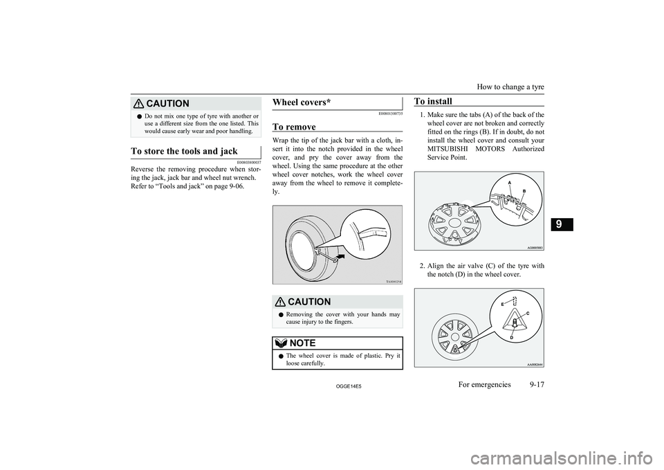
To remove
Wrap the tip of the jack bar with a cloth, in- sert it into the notch provided in the wheel
cover, and pry the cover away from the wheel. Using the same procedure at the other
wheel cover notches, work the wheel cover away from the wheel to remove it complete-
ly.
CAUTIONl Removing the cover with your hands may
cause injury to the fingers.NOTEl The wheel cover is made of plastic. Pry it
loose carefully.To install
1. Make sure the tabs (A) of the back of the
wheel cover are not broken and correctly fitted on the rings (B). If in doubt, do not install the wheel cover and consult your
MITSUBISHI MOTORS Authorized
Service Point.
2. Align the air valve (C) of the tyre with
the notch (D) in the wheel cover.
How to change a tyre
9-17OGGE14E5For emergencies9