weight MITSUBISHI OUTLANDER PHEV 2018 (in English) User Guide
[x] Cancel search | Manufacturer: MITSUBISHI, Model Year: 2018, Model line: OUTLANDER PHEV, Model: MITSUBISHI OUTLANDER PHEV 2018Pages: 538, PDF Size: 25.01 MB
Page 318 of 538
NOTElBecause the rear-view camera has a special
lens, the lines on the ground between park-
ing spaces may not look parallel on the screen.
l In the following situations, the screen indi-
cation may be difficult to see. There is no abnormality.
• Low light (nighttime).
• When the light of the sun or the light from
a vehicle’s headlamps shines directly into
the lens.
l If the camera is hot and is then cooled by
rain or a car wash, the lens can mist up. This
phenomenon does not indicate a malfunc- tion.
l It is not possible to fully see obstacles when
the lens is dirty. If the lens becomes conta- minated by water droplets, snow, mud or oil,
wipe off the contamination, taking care not to scratch the lens.
l Please observe the following cautions. Ig-
noring them could lead to a camera malfunc-
tion.
• Do not subject the camera to physical
shock.
• Do not apply wax to the camera.
• Do not splash the camera with boiling wa-
ter.
• Do not disassemble the camera.Reference lines on the screen
E00649100029
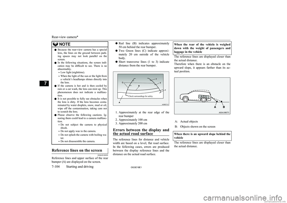
Reference lines and upper surface of the rear
bumper (A) are displayed on the screen.
l Red line (B) indicates approximately
50 cm behind the rear bumper.
l Two Green lines (C) indicate approxi-
mately 20 cm outside of the vehicle
body.
l Short transverse lines (1 to 3) indicate
distance from the rear bumper.Check surroundings for safety.
1. Approximately at the rear edge of the
rear bumper
2. Approximately 100 cm
3. Approximately 200 cm
Errors between the display and the actual road surface
The reference lines for distance and vehicle
width are based on a level, flat road surface. In the following cases, errors are produced between the display reference lines and the distance on the actual road surface.
When the rear of the vehicle is weighed
down with the weight of passengers and luggage in the vehicle
The reference lines are displayed closer than
the actual distance.
Therefore when there is an obstacle on the
upward slope, it appears farther than its ac- tual position.
A:Actual objectsB:Objects shown on the screen
When there is an upward slope behind the
vehicle
The reference lines are displayed closer than the actual distance.
Rear-view camera*
7-104OGGE18E1Starting and driving7
Page 325 of 538
NOTElWhen the expected course lines are dis-
played in the front-view, the expected course lines are also displayed in the bird’s eyeview(Front: solid line, Rear: broken line).Rear-view mode
E00645600084
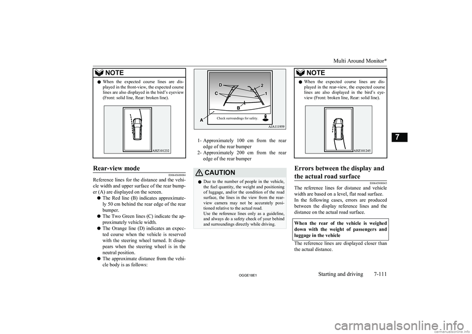
Reference lines for the distance and the vehi-
cle width and upper surface of the rear bump-
er (A) are displayed on the screen.
l The Red line (B) indicates approximate-
ly 50 cm behind the rear edge of the rear
bumper.
l The Two Green lines (C) indicate the ap-
proximately vehicle width.
l The Orange line (D) indicates an expec-
ted course when the vehicle is reserved
with the steering wheel turned. It disap- pears when the steering wheel is in the
neutral position.
l The approximate distance from the vehi-
cle body is as follows:
1- Approximately 100 cm from the rear
edge of the rear bumper
2- Approximately 200 cm from the rear
edge of the rear bumper
CAUTIONl Due to the number of people in the vehicle,
the fuel quantity, the weight and positioning of luggage, and/or the condition of the roadsurface, the lines in the view from the rear-
view camera may not be accurately posi- tioned relative to the actual road.
Use the reference lines only as a guideline,
and always do a safety check of your behind and surroundings directly while driving.NOTEl When the expected course lines are dis-
played in the rear-view, the expected course lines are also displayed in the bird’s eye-view (Front: broken line, Rear: solid line).Errors between the display and
the actual road surface
E00645900045
The reference lines for distance and vehicle width are based on a level, flat road surface.In the following cases, errors are produced between the display reference lines and the
distance on the actual road surface.
When the rear of the vehicle is weighed down with the weight of passengers and
luggage in the vehicle
The reference lines are displayed closer than the actual distance.
Multi Around Monitor*
7-111OGGE18E1Starting and driving7 Check surroundings for safety.
Page 329 of 538

Cargo loadsE00609902713
Cargo loads precautionsCAUTIONl Do not load cargo or luggage higher than the
top of the seatback. Be sure that your cargo
or luggage cannot move once your vehicle is moving. Having the driver’s vision blocked,
and your cargo being thrown inside the cab- in if you suddenly have to brake can cause a
serious accident or injury.
l Load heavy cargo or luggage in the front of
the vehicle. If the load in the back of the ve-
hicle is too heavy, steering may become un-
stable.
Loading a roof carrier
CAUTIONl Use a roof carrier that properly fits your ve-
hicle. Do not load luggage directly onto the
roof.
For installation, refer to the instruction man-
ual accompanying the roof carrier.NOTEl We recommend you to use a
MITSUBISHI
MOTORS GENUINE roof carrier, since the
brackets to be used have a special shape. For details, we recommend you to consult aMITSUBISHI MOTORS Authorized Serv-
ice Point.
Roof carrier precaution
CAUTIONl Make sure that the weight of the luggage
does not exceed the allowable roof load.
If the allowable roof load is exceeded, this may cause damage to the vehicle.
The roof load is the total allowable load on
the roof (the weight of the roof carrier plus
the weight of luggage placed on the roof car- rier).
For the specific value, refer to “Maximum
roof load” on page 12-05.CAUTIONl When luggage is loaded onto the vehicle,
please make sure to drive slowly and avoid
excessive manoeuvres such as sudden brak- ing or quick turning.
In addition, place the luggage on the carrier
so that its weight is distributed evenly with the heaviest items on the bottom. Do not load items that are wider than the roof carri-
er.
The additional weight on the roof could raise
the vehicle’s centre of gravity and affect ve-
hicle handling characteristics.
As a result, driving errors or emergency ma- noeuvres could lead to a loss of control and
result in an accident.
l Before driving and after travelling a short
distance, always check the load to make sure
it is securely fastened to the roof carrier.
Check periodically during your travel that the load remains secure.NOTEl To prevent wind noise or reduction in fuel
economy, remove the roof carrier when not
in use.
l Remove the roof carrier before using an au-
tomatic car wash.
l Be sure that adequate clearance is main-
tained for raising the sunroof (if so equip-
ped) when installing a roof carrier.
Cargo loads
7-115OGGE18E1Starting and driving7
Page 330 of 538
NOTElBe sure that adequate clearance is main-
tained for raising the tailgate while loading
luggage on the roof carrier.Trailer towing
E00610001906
In order to tow a trailer with your vehicle,
have a trailer towing device mounted that
meets all relevant regulations in your area, consult a MITSUBISHI MOTORS Author-
ized Service Point.
The regulations concerning the towing of a
trailer may differ from country to country. You are advised to obey the regulations in
each area.
CAUTIONl Danger of Accident!
A towing bar should be fitted according to MITSUBISHI MOTORS guidelines.
Maximum towable weight with
brake and maximum trailer- nose weight
Never exceed the maximum towable weight
with brake and the maximum trailer-nose weight as listed in the specifications.
(Refer to page “Vehicle weight” on page
12-05.)
If you tow a trailer at an altitude of more than
1,000 m above sea-level, reduce your weight by 10 % of the gross combination weight for
every increase of 1,000 m above sea-level, as
the engine output is lowered owing to de-
crease in atmospheric pressure.
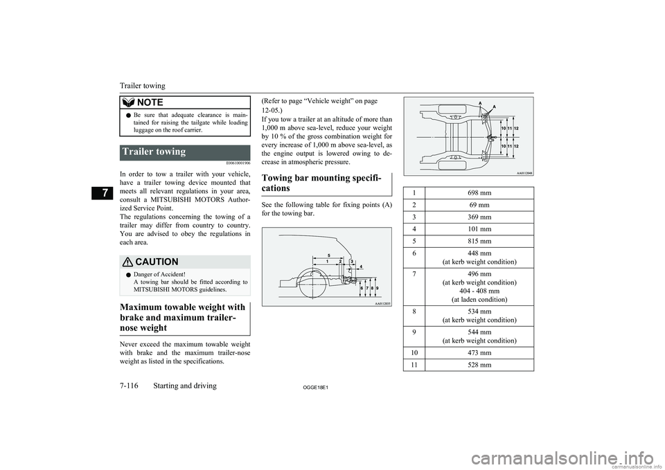
Towing bar mounting specifi-cations
See the following table for fixing points (A) for the towing bar.
1698 mm269 mm3369 mm4101 mm5815 mm6448 mm
(at kerb weight condition)7496 mm
(at kerb weight condition) 404 - 408 mm
(at laden condition)8534 mm
(at kerb weight condition)9544 mm
(at kerb weight condition)10473 mm11528 mm
Trailer towing
7-116OGGE18E1Starting and driving7
Page 417 of 538

Assist gripsE00732800298
The assist grips (located above the doors on the headliner) are not designed to support
body weight. They are intended for use only while seated in the vehicle.CAUTIONl Do not use the assist grips when getting into
or out of the vehicle. The assist grips could
detach causing you to fall.Coat hook
E00725601640
There is a coat hook on the rear seat assist
grip of the driver’s side.WARNINGl Do not put a hanger or any heavy or poin-
ted object on the coat hook. If the curtain
airbag was activated, any such item could
be propelled away with great force and could prevent the curtain airbag from in-
flating correctly. Hang clothes directly on the coat hook (without using a hanger).
Make sure there are no heavy or sharp objects in the pockets of clothes that you
hang on the coat hook.Luggage hooks
E00715700579
There are 4 hooks located on the side walls of
the luggage compartment.
Use the hooks for securing the luggage.CAUTIONl Do not pile up the luggage beyond the seat-
back height. Also, firmly secure the luggage. Otherwise, serious accidents could result due
to hindered rearward view or flying objects
during sudden braking.
Assist grips
8-85OGGE18E1For pleasant driving8
Page 479 of 538
Vehicle labeling................................................................................ 12-02
Vehicle dimensions........................................................................... 12-04
Vehicle performance......................................................................... 12-05 Vehicle weight.................................................................................. 12-05
Engine specifications........................................................................ 12-06
Charging system specifications.........................................................12-07
Electric motor specifications.............................................................12-08
Low voltage electrical system........................................................... 12-08Tyres and wheels...............................................................................12-08
Fuel consumption.............................................................................. 12-09
Refill capacities................................................................................. 12-10Specifications
OGGE18E112
Page 483 of 538

Minimum turning radiusBody5.76 mWheel5.3 m
Vehicle performanceE01100303553Maximum speed170 km/h
Vehicle weightE01100408719ItemExcept for S EditionS EditionLHDRHDLHDRHDKerb weightWithout op-tional parts1,860 kg1,880 kgWith full op- tional parts1,929 kg1,927 kg1,937 kg1,935 kgMaximum gross vehicle weight2,370 kgMaximum axle
weightFront1,160 kgRear1,255 kg, 1,365 kg *Maximum towable
weightWith brake1,500 kgWithout brake750 kgMaximum trailer-nose weight75 kg* : In case of trailer towing
Vehicle performance
12-05OGGE18E1Specifications12
Page 495 of 538

Towing.............................................................. 9-17
Trailer towing.................................................. 7-116
Transaxle fluid ................................................12-10
Turn-signal indication lamps.............................6-47
Turn/Lane-change signals................................. 6-60
Tyre pressure monitoring system (TPMS)........ 7-89
Tyre repair kit.................................................... 9-07
Tyres................................................................ 11-10 How to change a tyre.................................... 9-13
Inflation pressures....................................... 11-10
Rotation....................................................... 11-11
Size (tyre and wheel).................................. 12-08
Snow traction device (tyre chains).............. 11-13
Snow tyres................................................... 11-12
Tread wear indicators.................................. 11-11
Tyre pressure monitoring system (TPMS).. 11-10
Tyre repair kit............................................... 9-07
U
Ultrasonic misacceleration MitigationSystem (UMS)................................................. 7-74
USB input terminal............................................8-69 How to connect a USB memory................... 8-69
How to connect an iPod................................ 8-70
V
Vanity mirror lampBulb capacity.............................................. 11-25
Vehicle care precautions................................. 10-02
Vehicle dimensions......................................... 12-04
Vehicle identification number......................... 12-02
Vehicle identification number plate................ 12-02
Vehicle information code plate....................... 12-02
Vehicle labeling...............................................12-02
Vehicle performance....................................... 12-05
Vehicle weight.................................................12-05
Ventilators......................................................... 8-02
W
Warning lamps.................................................. 6-48
Washer Fluid.................................................. 11-08,12-10
Switch................................................... 6-65,6-66
Washing...........................................................10-03
Waxing............................................................ 10-04
Weight............................................................. 12-05
Wheel Specification............................................... 12-08
Wiper de-icer switch......................................... 6-67
Wiper Rear window................................................. 6-65Windscreen................................................... 6-62
Wiper blades............................................... 11-13
Alphabetical index
13- 5
OGGE18E1Alphabetical index