power steering MITSUBISHI OUTLANDER SPORT 2016 3.G Owners Manual
[x] Cancel search | Manufacturer: MITSUBISHI, Model Year: 2016, Model line: OUTLANDER SPORT, Model: MITSUBISHI OUTLANDER SPORT 2016 3.GPages: 398, PDF Size: 14.63 MB
Page 23 of 398
Front seats
Seat and restraint systems 4-3
4
Safety equipment cannot prevent injury or death in all motor vehicle accidents. You can help reduce the risk of injury or death, how- ever, by following the
instructions in this
manual.
N00401800399
Position the driver’s seat
as far back as possi-
ble while maintaining a position that stillenables you to fully apply the pedals, easily control the steering wheel and safely operate the vehicle.
N00401900228
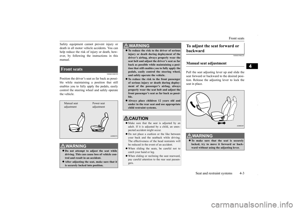
Pull the seat adjusting lever up and slide theseat forward or backward to the desired posi- tion. Release the adjusting lever to lock the seat in place.
Front seats
WA R N I N G Do not attempt to adjust the seat while driving. This can cause loss of vehicle con- trol and result in an accident. After adjusting the seat, make sure that it is securely locked into position.Manual seat adjustment
Power seat adjustment
To reduce the risk to the driver of serious injury or death during deployment of the driver’s airbag, always properly wear the seat belt and adjust th
e driver’s seat as far
back as possible while maintaining a posi-tion that still enables
you to fully apply the
pedals, easily control the steering wheel, and safely operate the vehicle. To reduce the risk to the front passenger of serious injury or death during deploy-ment of the passenger’s airbag, always properly wear the seat belt and adjust the front passenger’s seat as far back as possi-ble. Always place children 12 years old and under in the rear seat and use appropriate child restraint systems.CAUTION Make sure that the seat is adjusted by an adult. If it is adjusted by a child, an unex-pected accident might occur. Do not place a cushion or the like between your back and the seatback while driving. The effectiveness of the head restraints will be reduced in the event of an accident. When sliding the seats, be careful not to catch your hand or leg. When sliding or reclining the seat rearward, pay careful attention to the rear seat passen- gers.WA R N I N G
To adjust the seat forward or backward Manual seat adjustment
WA R N I N G To make sure that the seat is securely locked, try to move it forward or back- ward without using the adjusting lever.
BK0229600US.bo
ok 3 ページ 2015年10月1日 木曜日 午後2時29分
Page 63 of 398
5
Features and controlsBreak-in recommendation
s ..............................................................5-3
Keys ..........................................
.......................................................5-3
Electronic immobilizer (Anti-thef
t starting system) ........................5-4
Keyless entry system (if so equipped) ..............................................5-7Free-hand Advanced Security Transmitter (F.A.S.T.-key) (if so equipped)
.................................................
........................5-12
Door locks .......................
...............................................................5-28
Power door locks ............
...............................................................5-30
Child safety locks for r
ear door .....................................................5-31
Liftgate ......................................
.....................................................5-32
Inside liftgate releas
e .............................................
........................5-33
Theft-alarm system
................................................
........................5-34
Power window control
...........................................
........................5-37
Sunshade (if so equi
pped)..............................................................5-39
Parking brake ..................
...............................................................5-40
Steering wheel height and reach adjustment ..................................5-41Inside rearview mirro
r ...........................................
........................5-42
Outside rearview mirr
ors ...............................................................5-44
Ignition switch ......
.................................................
........................5-46
Starting the engine
.................................................
........................5-47
Manual transaxle (if so equipped) .................................................5-49 Continuously variable transmission
(CVT) (if so equipped).........5-51
Electronically controlled 4WD system (if so equipped)................5-584-wheel drive operation
.........................................
........................5-60
Inspection and maintenance following rough road operation ........5-63 Cautions on the handling of 4-wheel drive vehicles ......................5-63Service brake ..................
...............................................................5-64
Hill start assist .......
.................................................
........................5-65
Brake assist system
...............................................
......................... 5-66
Anti-lock braking syst
em .....................................
......................... 5-67
Electric power steering syst
em (EPS) ........................................... 5-69
Active stability control
(ASC) ....................
................................... 5-70
Cruise control (if so eq
uipped) ...................................................... 5-73
Tire pressure monitoring
system ................................................... 5-77
Rear-view camera (if so eq
uipped) ................................................ 5-81
Instrument cluster
.................................................
......................... 5-83
Multi-information disp
lay ....................................
......................... 5-85
Indicator light, warning light, and information screen disp
lay list ................................................. 5-106
Indicators .................................
.................................................... 5-119
Warning lights ................
.................................................
............. 5-120
Information screen disp
lay ...................................
....................... 5-121
Combination headlights and dimmer switch ............................... 5-123 Headlight leveling switch (if so equipped).................................. 5-129Turn signal lever ..
.................................................
....................... 5-129
Hazard warning flasher
switch .................................................... 5-130
Front fog light switch (if
so equipped) ........................................ 5-130
Wiper and washer swit
ch ......................................
....................... 5-130
Electric rear window def
ogger switch ......................................... 5-136
Horn switch .............................
.................................................... 5-136
Link System (if so equi
pped) .....................
................................. 5-137
Bluetooth
® 2.0 interface (if so
equipped)..................................... 5-137
USB input terminal (if so
equipped) ........................................... 5-160
Sun visors ......................
.................................................
............. 5-163
12 V power outlets .........
.................................................
............. 5-164
HomeLink
® Wireless Control System (if so equipped) ............... 5-165
BK0229600US.bo
ok 1 ページ 2015年10月1日 木曜日 午後2時29分
Page 84 of 398
Free-hand Advanced Security Transmitte
r (F.A.S.T.-key) (if so equipped)
5-22 Features and controls
5
When the ambient temperature is -22 °F (-30 °C) or lower, it may not be possible to start from a standstill even with the selector lever in the “D” (DRIVE) or “R” (REVERSE)position. This phenomenon occurs because the trans- axle has not warmed up sufficiently; it doesnot indicate a problem. If this occurs, place the selector lever in the “P” (PARK) position and let the engine idle for at least 10 minutes.The transaxle will warm up, and you will beable to start normally. Do not leave the vehicle during warm-up operation.
N00568200014
1. Stop the vehicle. 2. Fully engage the parking brake while depressing the brake pedal.3. On vehicles with a manual transaxle, press the engine switch to stop the engine, and then move the gearshift lever to the1st (on a uphill) or
“R” (Reverse) (on a
downhill) position. On vehicles equipped with continuouslyvariable transmission (CVT), move the selector lever to the “P” (PARK) position, and then press the engine switch to stopthe engine.
N00568301067
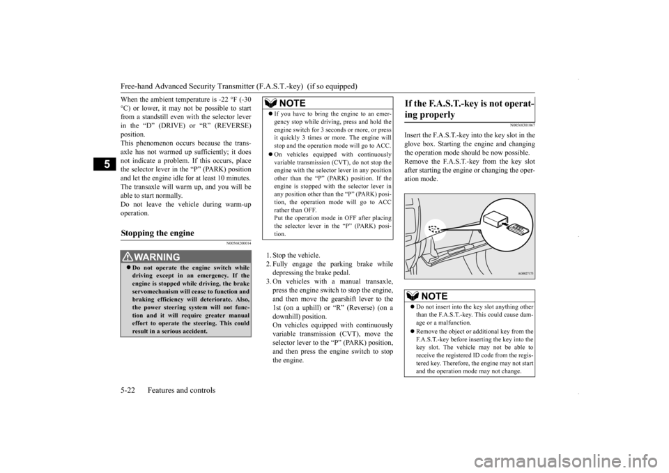
Insert the F.A.S.T.-key into the key slot in theglove box. Starting the engine and changing the operation mode should be now possible. Remove the F.A.S.T.-key from the key slotafter starting the engine or changing the oper- ation mode.
Stopping the engine
WA R N I N G Do not operate the engine switch while driving except in an emergency. If theengine is stopped while
driving, the brake
servomechanism will cease to function and braking efficiency will deteriorate. Also,the power steering system will not func- tion and it will require greater manual effort to operate the steering. This could result in a serious accident.
NOTE
If you have to bring the engine to an emer- gency stop while driving, press and hold the engine switch for 3 seco
nds or more, or press
it quickly 3 times or more. The engine will stop and the operation mode will go to ACC. On vehicles equipped with continuously variable transmission (CVT), do not stop theengine with the selector lever in any position other than the “P” (PARK) position. If the engine is stopped with the selector lever inany position other than
the “P” (PARK) posi-
tion, the operation mode will go to ACC rather than OFF.Put the operation mode in OFF after placing the selector lever in the “P” (PARK) posi- tion.
If the F.A.S.T.-key is not operat- ing properly
NOTE
Do not insert into the key slot anything other than the F.A.S.T.-key. This could cause dam-age or a malfunction. Remove the object or additional key from the F.A.S.T.-key before inserting the key into the key slot. The vehicle may not be able to receive the registered ID code from the regis-tered key. Therefore, the engine may not start and the operation mode may not change.
BK0229600US.bo
ok 22 ページ 2015年10月1日 木曜日 午後2時29分
Page 109 of 398
Starting the engine
Features and controls 5-47
5
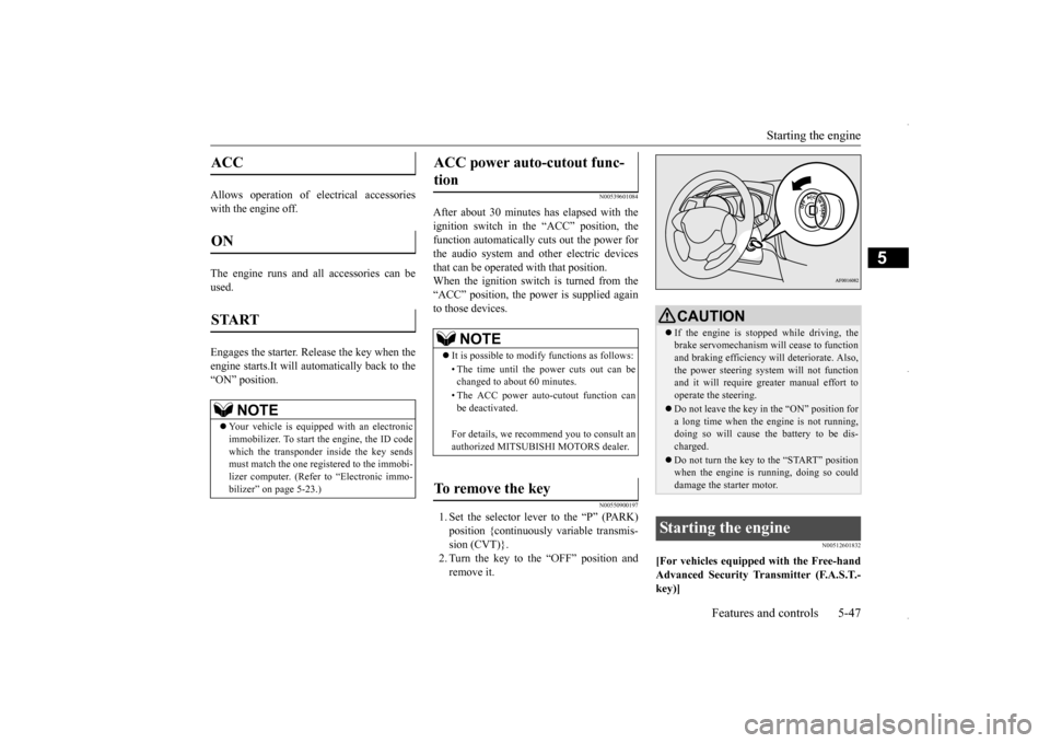
Allows operation of electrical accessories with the engine off. The engine runs and all accessories can be used. Engages the starter. Release the key when the engine starts.It will auto
matically back to the
“ON” position.
N00539601084
After about 30 minutes has elapsed with theignition switch in the “ACC” position, the function automatically cuts out the power for the audio system and other electric devicesthat can be operated with that position. When the ignition switch is turned from the “ACC” position, the power is supplied againto those devices.
N00550900197
1. Set the selector lever to the “P” (PARK) position {continuously variable transmis- sion (CVT)}.2. Turn the key to the “OFF” position and remove it.
N00512601832
[For vehicles equipped with the Free-handAdvanced Security Transmitter (F.A.S.T.- key)]
ACC ON START
NOTE
Your vehicle is equipped with an electronic immobilizer. To start the engine, the ID code which the transponder inside the key sendsmust match the one registered to the immobi- lizer computer. (Refer to “Electronic immo- bilizer” on page 5-23.)
ACC power auto-cutout func- tion
NOTE
It is possible to modify functions as follows: • The time until the power cuts out can be changed to about 60 minutes. • The ACC power auto-cutout function can be deactivated. For details, we recommend you to consult an authorized MITSUBISHI MOTORS dealer.
To remove the key
CAUTION If the engine is stopped while driving, the brake servomechanism will cease to function and braking efficiency will deteriorate. Also, the power steering system will not functionand it will require greater manual effort to operate the steering. Do not leave the key in the “ON” position for a long time when the engine is not running, doing so will cause the battery to be dis-charged. Do not turn the key to the “START” position when the engine is running, doing so could damage the starter motor.
Starting the engine
BK0229600US.bo
ok 47 ページ 2015年10月1日 木曜日 午後2時29分
Page 131 of 398
Electric power steering system (EPS)
Features and controls 5-69
5
The anti-lock braking system and brake force distribution function may not work, so hard braking could make the vehicle unstable. Avoid hard braking and high-speed driving.Stop the vehicle in a safe place and contact an authorized MITSUBISHI MOTORS dealer or repair facility of your choice.
N00529200077
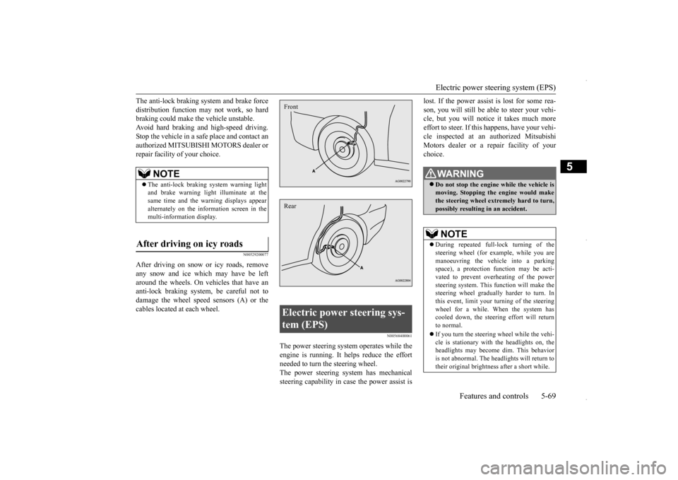
After driving on snow or icy roads, removeany snow and ice which may have be left around the wheels. On vehicles that have an anti-lock braking system, be careful not todamage the wheel speed sensors (A) or the cables located at each wheel.
N00568400061
The power steering system operates while the engine is running. It helps reduce the effortneeded to turn the steering wheel. The power steering system has mechanical steering capability in case the power assist is
lost. If the power assist is lost for some rea- son, you will still be able to steer your vehi- cle, but you will notice it takes much more effort to steer. If this happens, have your vehi-cle inspected at an authorized Mitsubishi Motors dealer or a repair facility of your choice.
NOTE
The anti-lock braking system warning light and brake warning light
illuminate at the
same time and the warning displays appear alternately on the information screen in the multi-information display.
After driving on icy roads
Electric power steering sys- tem (EPS) FrontRear
WA R N I N G Do not stop the engine while the vehicle is moving. Stopping the engine would makethe steering wheel extremely hard to turn, possibly resulting in an accident.NOTE
During repeated full-lock turning of the steering wheel (for example, while you are manoeuvring the vehicle into a parking space), a protection function may be acti-vated to prevent overheating of the power steering system. This function will make the steering wheel gradually harder to turn. Inthis event, limit your turning of the steering wheel for a while. When the system has cooled down, the steering effort will return to normal. If you turn the steering wheel while the vehi- cle is stationary with the headlights on, the headlights may become dim. This behavioris not abnormal. The headlights will return to their original brightness after a short while.
BK0229600US.bo
ok 69 ページ 2015年10月1日 木曜日 午後2時29分
Page 132 of 398
Active stability control (ASC) 5-70 Features and controls
5
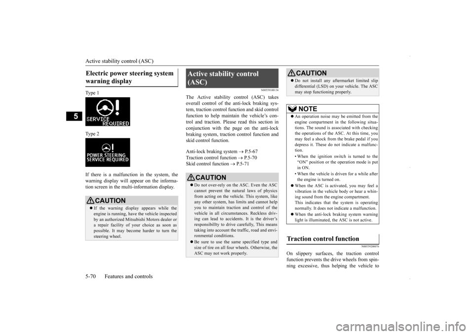
Ty p e 1 Ty p e 2 If there is a malfunction in the system, the warning display will appear on the informa-tion screen in the multi-information display.
N00559100134
The Active stability control (ASC) takesoverall control of the anti-lock braking sys-tem, traction control function and skid control function to help maintain the vehicle’s con- trol and traction. Please read this section inconjunction with the page on the anti-lock braking system, traction control function and skid control function. Anti-lock braking system
P.5-67
Traction control function
P.5-70
Skid control function
P.5-71
N00559200076
On slippery surfaces, the traction control function prevents the dr
ive wheels from spin-
ning excessive, thus helping the vehicle to
Electric power steering system warning display
CAUTION If the warning display appears while the engine is running, have the vehicle inspected by an authorized Mitsubishi Motors dealer ora repair facility of
your choice as soon as
possible. It may become harder to turn the steering wheel.
Active stability control (ASC)
CAUTION Do not over-rely on the ASC. Even the ASC cannot prevent the natural laws of physics from acting on the vehicle. This system, like any other system, has limits and cannot helpyou to maintain traction and control of the vehicle in all circumstances. Reckless driv- ing can lead to accidents. It is the driver’sresponsibillty to drive carefully, This means taking into account the traffic, road and envi- ronmental conditions. Be sure to use the same specified type and size of tire on all four wheels. Otherwise, the ASC may not work properly.
Do not install any aftermarket limited slip differential (LSD) on your vehicle. The ASC may stop functioning properly.NOTE
An operation noise may be emitted from the engine compartment in the following situa- tions. The sound is associated with checkingthe operations of the ASC. At this time, you may feel a shock from the brake pedal if you depress it. These do not indicate a malfunc-tion. • When the ignition switch is turned to the “ON” position or the operation mode is put in ON. • When the vehicle is driven for a while after the engine is turned on.
When the ASC is activated, you may feel a vibration in the vehicle body or hear a whin- ing sound from the engine compartment.This indicates that the system is operating normally. It does not indicate a malfunction. When the anti-lock braking system warning light is illuminated, the ASC is not active.
Traction control function
CAUTION
BK0229600US.bo
ok 70 ページ 2015年10月1日 木曜日 午後2時29分
Page 173 of 398
Indicator light, warning light, an
d information screen display list Features and controls 5-111
5
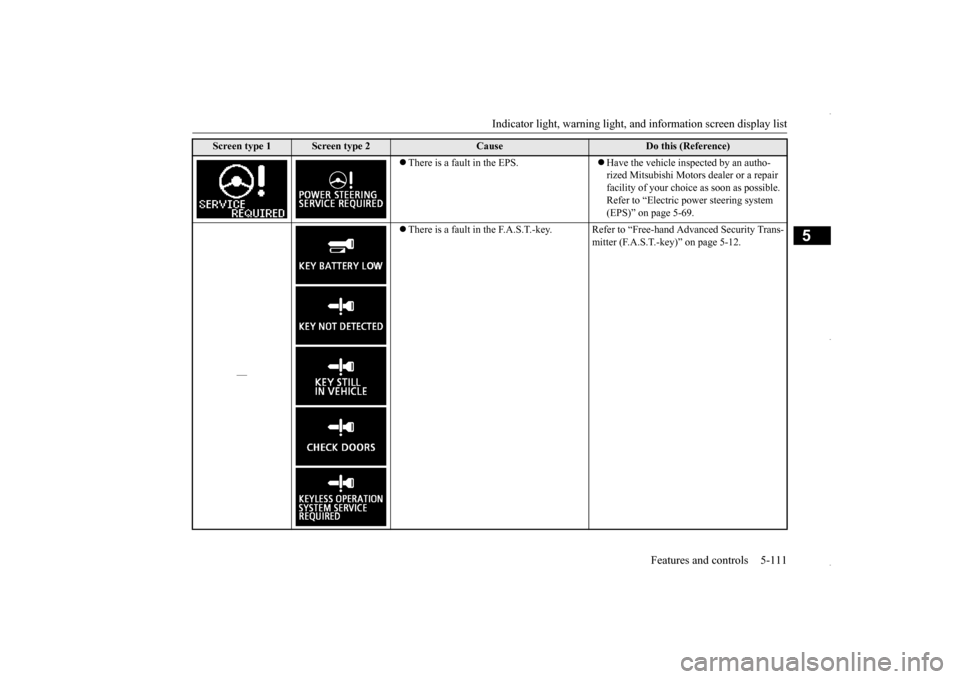
There is a fault in the EPS.
Have the vehicle inspected by an autho- rized Mitsubishi Motors dealer or a repair facility of your choice as soon as possible.Refer to “Electric power steering system (EPS)” on page 5-69.
—
There is a fault in the F.A.S.T.-key. Refer to “Free-hand Advanced Security Trans-
mitter (F.A.S.T.-key)” on page 5-12.
Screen type 1
Screen type 2
Cause
Do this (Reference)
BK0229600US.book
111 ページ 2015年10月1日 木曜日 午後2時29分
Page 200 of 398
Bluetooth® 2.0 interface (if so equipped) 5-138 Features and controls
5
Steering control switch and microphone
P.5-138 Voice recognition function
P.5-140
Useful voice commands
P.5-140
Speaker enrollment function
P.5-142
Connecting the Bluetooth
® 2.0 interface and
the Bluetooth
® device
P.5-144
Operating a music player connected via Blue- tooth
® P.5-150
How to make or receive hands-free calls
P.5-150 Phonebook function
P.5-153
N00564001167
Press this button to increase the volume.
NOTE
If the ignition switch or the operation mode is left in ACC, the accessory power will automatically turn off after a certain period of time and you will no longer be able to use the Bluetooth
® 2.0 interface. The accessory
power comes on again if the ignition switch or the engine switch is operated. Refer to “ACC power auto-cutout function” on page5-47. The Bluetooth
® 2.0 interface cannot be used
if the Bluetooth
® device has a dead battery
or the device power is turned off. Hands-free calls will not be possible if your phone does not have service available. If you place the Bluetooth
® device in the
luggage compartment, you may not be able to use the Bluetooth
® 2.0 interface.
Some Bluetooth
® devices are not compatible
with the Bluetooth
® 2.0 interface.
You can confirm the Link System software version by pressing the HANG-UP button 3times (press and hold 2 times and then press briefly) within 10 seconds.
For details of the Bluetooth
® 2.0 interface,
refer to the following web site:[For vehicles sold in U.S.A.] You can see to access the MITSUBISHI MOTORS NORTH AMERICA website.[For vehicles sold in Canada and MEXICO] You can see to access via the MITSUBISHI MOTORS website.Please read and agree to the “Warning about Links to the Web Sites of Other Companies”. The websites mentioned above may connectyou to websites other than the MITSUBISHI MOTORS website. http://www.mitsubishi-motors.com/en/prod-ucts/index.html Software updates by cellular phone/digital audio device manufacturers may change/alter device connectivity.NOTE
Steering control switch and microphone
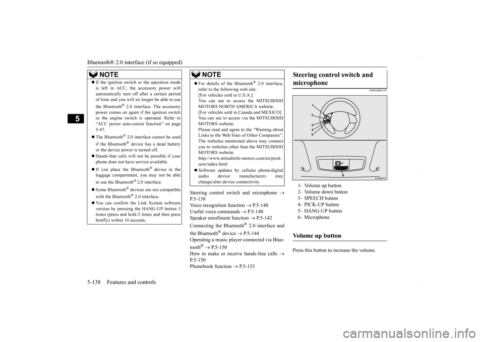
1- Volume up button 2- Volume down button3- SPEECH button 4- PICK-UP button 5- HANG-UP button6- MicrophoneVolume up button
BK0229600US.book
138 ページ 2015年10月1日 木曜日 午後2時29分
Page 248 of 398
Parking 6-6 Driving safety
6
On snowy roads, ice can form on the braking system, making the brakes less effective.While driving in such
conditions, pay close
attention to preceding and following vehicles and to the condition of
the road surface. From
time to time, lightly depress the brake pedal and check how effective the brakes are. It is important to take advantage of the engine braking by downshifting while driving on steep downhill roads in order to prevent the brakes from overheating.
N00629600304
When parking on a hill, set the parking brake,and turn the front wheels toward the curb on adownhill, or away from the curb on an uphill. If necessary, apply chocks to wheels.
Place the gearshift lever into the “R” (Reverse) position when parking on a down- hill slope, into the 1st position when parkingon an uphill slope. Be sure that the parking brake is firmly set when parked and that the selector lever is in the “P” (PARK) position. When parking on a hill, it is important to setthe parking brake before moving the selector lever to the “P” (PARK) position. This pre- vents loading the parking brake against thetransaxle. When this happens, it is difficult to move the selector lever out of the “P” (PARK) position. Never leave the engi
ne running while you
take a short sleep or rest. Also, never leave the engine running in a closed or poorly ven- tilated place.
Your front bumper can be damaged if you scrape it over curbs or parking stop blocks.Be careful when traveling up or down steep slopes where your bumper can scrape the road. More effort could be required to turn the steering wheel. Refer to “Electric power steering system (EPS)” on page 5-69.
When driving in cold weather When driving downhill Parking Parking on a hill
For vehicles equipped with man- ual transaxle For vehicles equipped with contin- uously variable transmission (CVT) Parking with the engine run- ning
WA R N I N G Leaving the engine running risks injury or death from accidentally moving the gear- shift lever (manual transaxle) or the selec- tor lever (CVT) or from the accumulation of toxic exhaust fumes in the passengercompartment.
Where you park
WA R N I N G Do not park your vehicle in areas where combustible materials such as dry grass or leaves can come in contact with a hotexhaust, since a fire could occur.
Do not keep the steering wheel fully turned for a long time
BK0229600US.bo
ok 6 ページ 2015年10月1日 木曜日 午後2時29分
Page 249 of 398
Loading information Driving safety 6-7
6
Always remove the key from the ignition switch and lock all doors and the liftgatewhen leaving the vehicle unattended. Always try to park your vehicle in a well lit area.
N00629900408
It is very importan
t to know how much
weight your vehicle can carry. This weight is called the vehicle capacity weight andincludes the weight of all occupants, cargo (including the roof load), non-factory- installed options, if any, being towed. The tireand loading information placard located on the driver’s door sill of your vehicle will show how much weight it may properly carry. It is important to fami
liarize yourself with the
following terms before loading your vehicle:
Vehicle maximum load on the tire: load on an individual tire that is determined by distributing to each axle its share of the maximum loaded vehicle weight anddividing by two. Vehicle normal load on the tire: load on an individual tire that is determined bydistributing to each axle its share of the curb weight, accessory weight, and nor- mal occupant weight and dividing by two. Maximum loaded vehicle weight: the sum of - (a) Curb weight; (b) Accessory weight;(c) Vehicle capacity weight; and (d) Production options weight. Curb weight: the weight of a motor vehi- cle with standard equipment including the maximum capacity of fuel, oil, and cool- ant. Accessory weight: the combined weight (in excess of those standard items which may be replaced) of automatic transmis-sion, power steering, power brakes, power windows, power seats, radio, and heater, to the extent that these items are availableas factory- installed equipment (whether installed or not). Vehicle capacity weight: the rated cargo and luggage load plus 150 lbs (68 kg)
*
times the vehicle’s designated seating capacity.
Production options weight: the combined weight of those installed regular produc- tion options weighing over 5 lbs (2.3 kg) in excess of those standard items whichthey replace, not previously considered in curb weight or accessory weight, includ- ing heavy duty brakes, ride levelers, roofrack, heavy duty battery, and special trim. Normal occupant weight: 150 lbs (68 kg)
* times the number of specified
occupants. (In your vehicle the number is3) Occupant distribution: Occupant distribu- tion within the passenger compartment (Inyour vehicle the distribution is 2 in front, 1 in second row seat)
N00630100383
The tire and loading information placard is located on the inside sill of the driver’s door.
When leaving the vehicle Loading information
WA R N I N G Never overload your vehicle. Overloading can damage your vehicle, adversely affect vehicle performance, including handling and braking, cause tire failure, and result in an accident.
* :150 lbs (68 kg) is the weight of one per- son as defined by U.S.A. and Canadian regulations.
Tire and loading information placard
BK0229600US.bo
ok 7 ページ 2015年10月1日 木曜日 午後2時29分