low beam MITSUBISHI SHOGUN 2017 Owner's Manual (in English)
[x] Cancel search | Manufacturer: MITSUBISHI, Model Year: 2017, Model line: SHOGUN, Model: MITSUBISHI SHOGUN 2017Pages: 394, PDF Size: 19 MB
Page 96 of 394
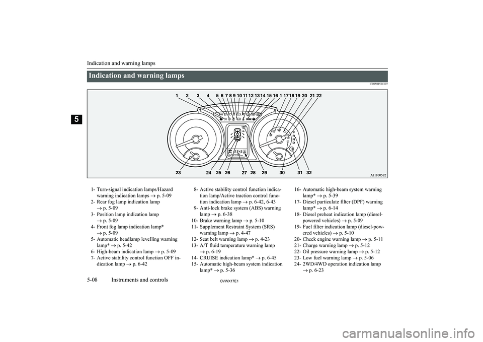
Indication and warning lampsE005015041071- Turn-signal indication lamps/Hazardwarning indication lamps ® p. 5-09
2- Rear fog lamp indication lamp ® p. 5-09
3- Position lamp indication lamp ® p. 5-09
4- Front fog lamp indication lamp* ® p. 5-09
5- Automatic headlamp levelling warning lamp* ® p. 5-42
6- High-beam indication lamp ® p. 5-09
7- Active stability control function OFF in- dication lamp ® p. 6-428- Active stability control function indica-
tion lamp/Active traction control func-
tion indication lamp ® p. 6-42, 6-43
9- Anti-lock brake system (ABS) warning lamp ® p. 6-38
10- Brake warning lamp ® p. 5-10
11- Supplement Restraint System (SRS) warning lamp ® p. 4-47
12- Seat belt warning lamp ® p. 4-23
13- A/T fluid temperature warning lamp ® p. 6-19
14- CRUISE indication lamp* ® p. 6-45
15- Automatic high-beam system indication lamp* ® p. 5-3616- Automatic high-beam system warning
lamp* ® p. 5-39
17- Diesel particulate filter (DPF) warning lamp* ® p. 6-14
18- Diesel preheat indication lamp (diesel- powered vehicles) ® p. 5-09
19- Fuel filter indication lamp (diesel-pow- ered vehicles) ® p. 5-10
20- Check engine warning lamp ® p. 5-11
21- Charge warning lamp ® p. 5-12
22- Oil pressure warning lamp ® p. 5-12
23- Low fuel warning lamp ® p. 5-06
24- 2WD/4WD operation indication lamp ® p. 6-23
Indication and warning lamps
5-08OVWX17E1Instruments and controls5
Page 97 of 394
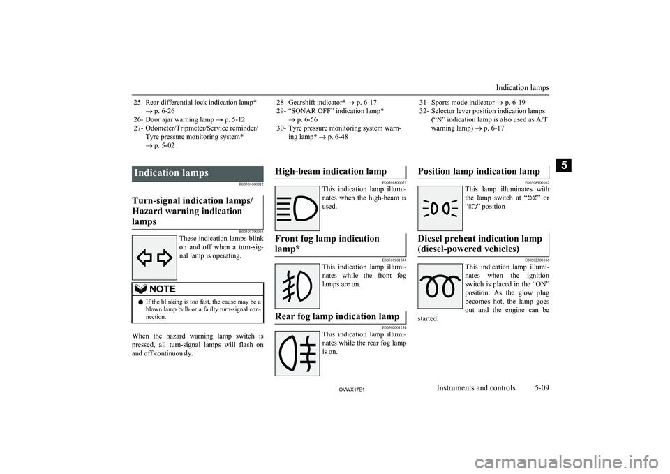
25- Rear differential lock indication lamp*® p. 6-26
26- Door ajar warning lamp ® p. 5-12
27- Odometer/Tripmeter/Service reminder/ Tyre pressure monitoring system*
® p. 5-0228- Gearshift indicator* ® p. 6-17
29- “SONAR OFF” indication lamp* ® p. 6-56
30- Tyre pressure monitoring system warn- ing lamp* ® p. 6-4831- Sports mode indicator ® p. 6-19
32- Selector lever position indication lamps (“N” indication lamp is also used as A/T
warning lamp) ® p. 6-17
Indication lamps
E00501600012Turn-signal indication lamps/
Hazard warning indication lamps
E00501700068
These indication lamps blink
on and off when a turn-sig-
nal lamp is operating.
NOTEl If the blinking is too fast, the cause may be a
blown lamp bulb or a faulty turn-signal con-
nection.
When the hazard warning lamp switch is
pressed, all turn-signal lamps will flash on and off continuously.
High-beam indication lamp
E00501800072
This indication lamp illumi-
nates when the high-beam is used.
Front fog lamp indication
lamp*
E00501901533
This indication lamp illumi-
nates while the front fog lamps are on.
Rear fog lamp indication lamp
E00502001254
This indication lamp illumi-
nates while the rear fog lamp is on.
Position lamp indication lamp
E00508900102
This lamp illuminates with
the lamp switch at “
” or
“
” position
Diesel preheat indication lamp
(diesel-powered vehicles)
E00502300146
This indication lamp illumi-
nates when the ignition
switch is placed in the “ON”
position. As the glow plug becomes hot, the lamp goes
out and the engine can be
started.
Indication lamps
5-09OVWX17E1Instruments and controls5
Page 124 of 394
NOTElThe lamp auto-cutout will not function when
the lamp switch is in the “” position
l When the ignition key has been turned to ei-
ther the “LOCK” or “ACC” position or re- moved from the ignition switch with the
lamp switch in the “
” position, and the
lamp switch is returned to the “OFF” within
approximately 3 minutes, the auto-cutout function will not be activated.
When you want to keep the
lamps on
l Turn the lamp switch in the “OFF” posi-
tion while the ignition switch is in the
“LOCK” or “ACC” position.
l Turn on the lamps with the switch in the
“
” or “” position again, then the
lamps will remain on.
l Remove the ignition key.
NOTElFor further information, we recommend you
to consult a MITSUBISHI MOTORS Au-
thorized Service Point.Lamp monitor buzzer
E00506100256
If the driver’s door is opened when the key is
in the “LOCK” or “ACC” position or re-
moved from the ignition switch while the
lamps are on, a buzzer will sound to remind the driver to turn off the lamps.
When the lamp auto-cutout function acts, the
buzzer will stop automatically.
Dipper (High/Low beam
change)
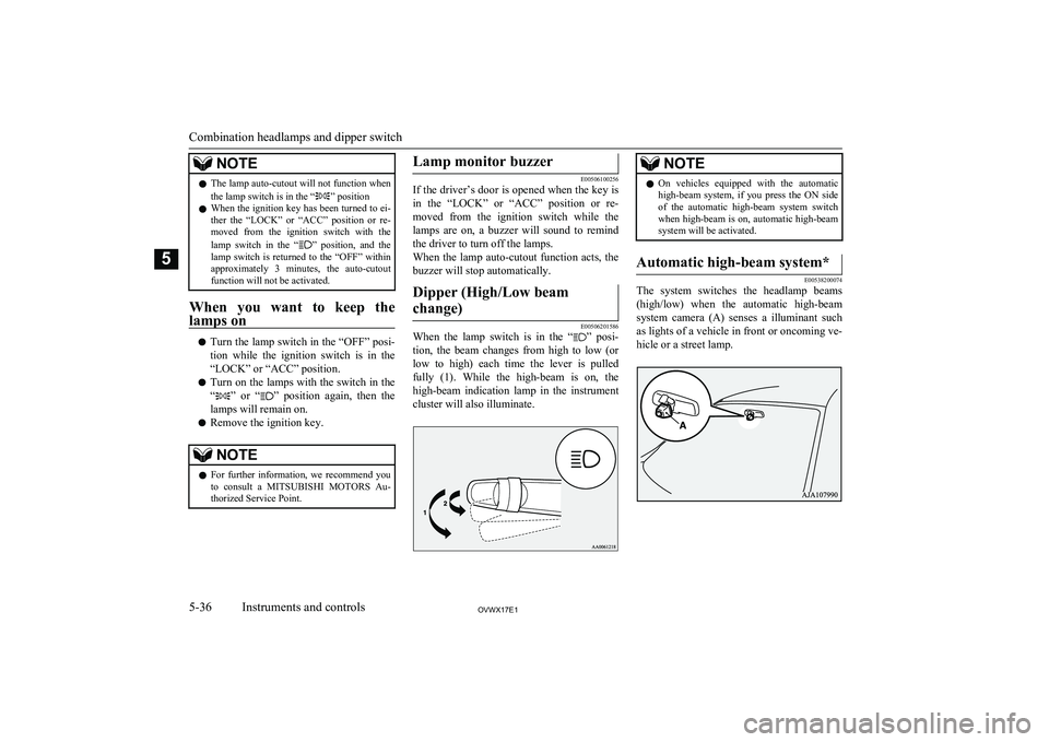
E00506201586
When the lamp switch is in the “” posi-
tion, the beam changes from high to low (or
low to high) each time the lever is pulled fully (1). While the high-beam is on, the
high-beam indication lamp in the instrument
cluster will also illuminate.
NOTEl On vehicles equipped with the automatic
high-beam system, if you press the ON side
of the automatic high-beam system switch when high-beam is on, automatic high-beam
system will be activated.Automatic high-beam system*
E00538200074
The system switches the headlamp beams
(high/low) when the automatic high-beam system camera (A) senses a illuminant such as lights of a vehicle in front or oncoming ve-
hicle or a street lamp.
Combination headlamps and dipper switch
5-36OVWX17E1Instruments and controls5
Page 125 of 394
WARNINGlThe headlamp beams (high/low) may not
be switched automatically under certain
circumstances. Do not overestimate the system. It is the responsibility of the driv-
er to switch the headlamp beams (high/
low) manually to suit each driving condi- tion.
Refer to “Dipper (High/Low beam
change)” on page 5-36.
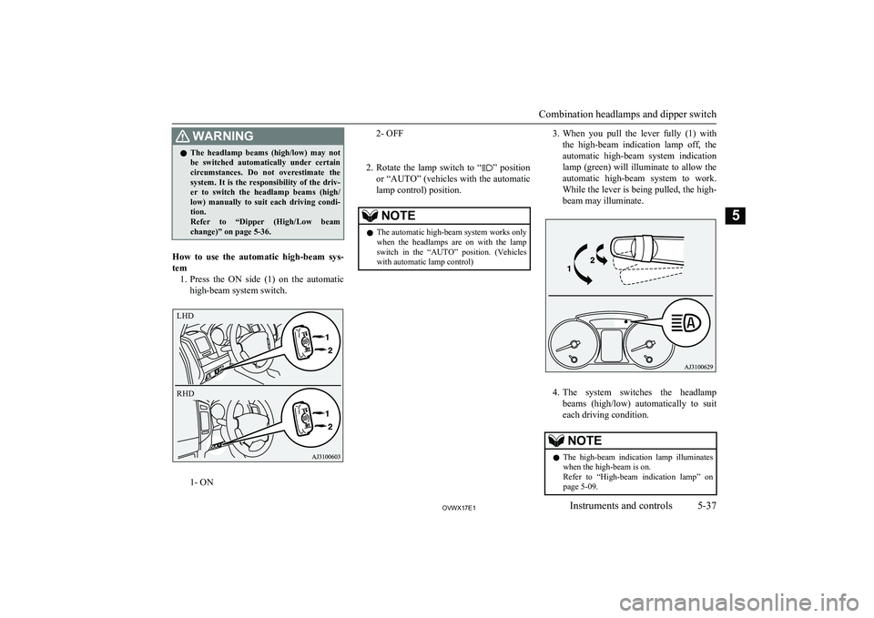
How to use the automatic high-beam sys-
tem 1. Press the ON side (1) on the automatic
high-beam system switch.
1- ON
2- OFF
2. Rotate the lamp switch to “
” position
or “AUTO” (vehicles with the automatic lamp control) position.
NOTEl The automatic high-beam system works only
when the headlamps are on with the lamp switch in the “AUTO” position. (Vehicles with automatic lamp control)3. When you pull the lever fully (1) with
the high-beam indication lamp off, the
automatic high-beam system indication
lamp (green) will illuminate to allow the automatic high-beam system to work.
While the lever is being pulled, the high- beam may illuminate.
4. The system switches the headlamp
beams (high/low) automatically to suit each driving condition.
NOTEl The high-beam indication lamp illuminates
when the high-beam is on.
Refer to “High-beam indication lamp” on
page 5-09.
Combination headlamps and dipper switch
5-37OVWX17E1Instruments and controls5 LHD
RHD
Page 126 of 394
NOTElYou can switch the headlamp beams (high/
low) manually by operating the lever even if the automatic high-beam system is working.Refer to “Dipper (High/Low beam change)”
on page 5-36.
If the lever is operated manually, the auto-
matic high-beam system indication lamp will go off and the automatic high-beam sys- tem will be deactivated.
l The automatic high-beam system is not de-
activated when you pull the lever slightly
(2).
5. To deactivate the automatic high-beam
system, press the OFF side (2) on the au- tomatic high-beam system switch.
Automatic switching conditions
The high-beam headlamps illuminate when all of the following conditions are met:
l Your vehicle speed exceeds approxi-
mately 40 km/h (25 mph).
l It is dark ahead of your vehicle.
l There are no vehicles in front or oncom-
ing vehicles, or none of their exterior
lamps are illuminated.
The low beam headlamps illuminate when
any of the following conditions occur:
l Your vehicle speed does not exceed ap-
proximately 30 km/h (19 mph).
l It is bright ahead of your vehicle.
l An exterior lamp of a vehicle in front or
oncoming vehicle is illuminating.NOTEl The headlamps may not be switched from
high-beam to low beam under the following circumstances.
• A vehicle in front or oncoming vehicle is
hindered by any object such as continuous
bends, elevated median/island, traffic
signs, roadside trees.
• Your vehicle passes an oncoming vehicle
suddenly on a bend with poor visibility.
• Another vehicle crosses ahead of your ve-
hicle
l The headlamps may remain at low beam (or
be switched from high-beam to low beam)
when a reflective object (e.g. street lamp,
traffic signal, noticeboard and signboard) re- flects light.
l Any of the following factors may influence
the headlamp beam switching timing:
• How brightly the exterior lamps of a vehi-
cle in front or oncoming vehicle illumi-
nate.
• Movement or direction of a vehicle in
front or oncoming vehicle.
• Only right or left exterior lamp of a vehi-
cle in front or oncoming vehicle is illumi-
nating.NOTE• A vehicle in front or oncoming vehicle is
a motorcycle.
• Road conditions (gradient, bends and road
surface).
• The number of occupants and luggage
load.
l The automatic high-beam system recognises
environmental conditions by sensing a lightsource ahead of your vehicle. Therefore, you
may feel like something is not quite right
when the headlamp beams are switched au- tomatically.
l The system may not detect a light vehicle
such as a bicycle.
l The system may not detect an ambient
brightness precisely. This causes the trafficto be dazzled by high-beam or the low beam
to be maintained. In such cases, you should switch the headlamp beams manually.
• In bad weather (heavy rain, fog, snow or
sandstorm).
• The windscreen is dirty or fogged up.
• The windscreen is cracked or broken.
• The inside rear view mirror or the camera
is deformed or dirty.
• A light, which is similar to the headlamps
or tail lamps, is shining around your vehi-
cle
• A vehicle in front or oncoming vehicle is
driven without lights, the exterior lamps
are dirty or discoloured, or the direction of the headlamp beams is adjusted im- properly
Combination headlamps and dipper switch
5-38OVWX17E1Instruments and controls5
Page 127 of 394
NOTE•It becomes dark and bright suddenly and
continuously around your vehicle.
• Your vehicle is driven on uneven surfa-
ces.
• Your vehicle is driven on a winding road.
• A reflective object such as a noticeboard
or a mirror reflects a light ahead of yourvehicle
• The rear end of a vehicle in front (such as
a container truck) reflect a strong light.
• Your vehicle’s headlamp is broken or
dirty.
• Your vehicle is inclined due to a flat tyre
or towing.
• The automatic high-beam system warning
lamp comes on.
l Observe the precautions below to maintain
good usage conditions:
• Do not touch the camera lens.
• Do not subject the inside rear view mirror
and the camera to strong impact. Do not spill any liquid over them.
• Do not attempt to disassemble the camera.
• Do not affix a sticker or label on the
windscreen near the camera.
• Do not place any objects on the instru-
ment panel.
• Do no hang any accessories around the in-
side rear view mirror or the camera.
• Avoid overload.
• Do not modify your vehicle.
• When the windscreen is replaced, use the
MITSUBISHI MOTORS genuine parts.Automatic high-beam system
warning lamp
E00538300046
The automatic high-beam system warning
lamp (yellow) will illuminate when the auto-
matic high-beam system detects any fault when the ignition switch is in the “ON” posi-
tion.
CAUTIONl If the warning lamp comes on, we recom-
mend you to have the system checked.NOTEl If the warning lamp comes on, press the
OFF side (2) on the automatic high-beam
system switch to deactivate the system. It is the responsibility of the driver to switch theheadlamp beams (high/low) manually to suit
each driving condition.
Refer to “Dipper (High/Low beam change)”
on page 5-36.Headlamp flasher
E00506300128
The high-beams flash when the lever is
pulled slightly (2), and will go off when it is
released.
When the high-beam is on, the high-beam in- dication lamp in the instrument cluster will il-
luminate.
NOTEl The high-beams can also flash when the
lamp switch is OFF.
l If you turn the lamps off with the headlamps
set to high-beam, the headlamps are auto- matically returned to their low-beam setting
when the lamp switch is next turned to the
“
” position.
Combination headlamps and dipper switch
5-39OVWX17E1Instruments and controls5
Page 128 of 394
Headlamp levellingE00517400015Headlamp levelling switch*
E00517501970
Except for vehicles with dis-
charge headlamps
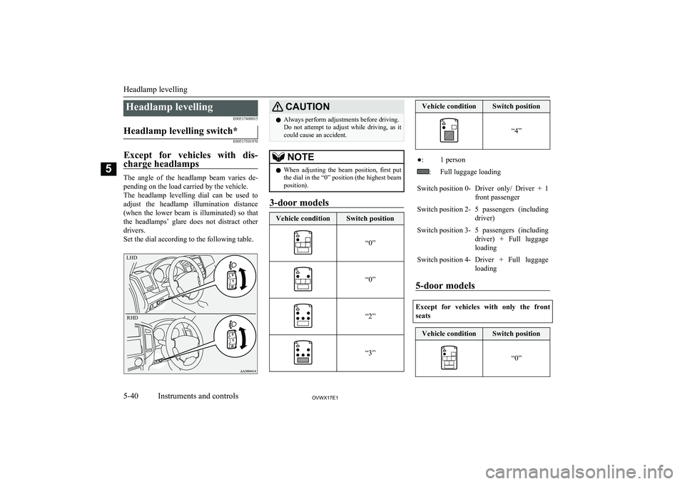
The angle of the headlamp beam varies de- pending on the load carried by the vehicle.The headlamp levelling dial can be used to
adjust the headlamp illumination distance (when the lower beam is illuminated) so that
the headlamps’ glare does not distract other drivers.
Set the dial according to the following table.
LHDRHD
CAUTIONl Always perform adjustments before driving.
Do not attempt to adjust while driving, as it could cause an accident.NOTEl When adjusting the beam position, first put
the dial in the “0” position (the highest beamposition).
3-door models
Vehicle conditionSwitch position
“0”“0”“2”“3”
Vehicle conditionSwitch position
“4”
●:1 person:Full luggage loadingSwitch position 0-Driver only/ Driver + 1
front passengerSwitch position 2-5 passengers (including
driver)Switch position 3-5 passengers (including
driver) + Full luggage loadingSwitch position 4-Driver + Full luggageloading
5-door models
Except for vehicles with only the front seats
Vehicle conditionSwitch position
“0”Headlamp levelling
5-40OVWX17E1Instruments and controls5
Page 339 of 394
No.SymbolElectricalsystemCapaci- ty15Hazard warn-ing flasher10 A16Stop lamps15 A17Radio10 A18Room lamp15 A19Air condition- ing10 A20Front foglamps15 A21———22Windscreen wiper20 A23Tail lamp(right)7.5 A24Tail lamp (left)7.5 A25Headlamp lowbeam (right)10 A *220 A*326Headlamp low
beam (left)10 A *2*1
: Fusible link
*2 : Vehicles without discharge headlamps
*3 : Vehicles with discharge headlampsNo.SymbolElectrical
systemCapaci- ty20 A *327
Headlamp
high-beam (right)
10 A28
Headlamp
high-beam (left)
10 A29Audio40 A *130Heater50 A*1*1
: Fusible link
*2 : Vehicles without discharge headlamps
*3 : Vehicles with discharge headlamps
l Some fuses may not be installed on your
vehicle, depending on the vehicle model
or specifications.
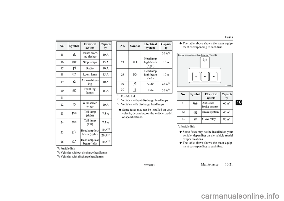
l The table above shows the main equip-
ment corresponding to each fuse.Engine compartment fuse location (Type B)No.SymbolElectrical systemCapaci- ty31Anti-lock
brake system60 A *32Brake system40 A*33Glow relay80 A**
: Fusible link
l Some fuses may not be installed on your
vehicle, depending on the vehicle model
or specifications.
l The table above shows the main equip-
ment corresponding to each fuse.
Fuses
10-21OVWX17E1Maintenance10
Page 342 of 394
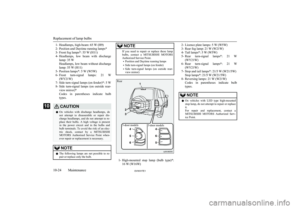
1- Headlamps, high-beam: 65 W (H9)
2- Position and Daytime running lamps*
3- Front fog lamps*: 55 W (H11)
4- Headlamps, low beam with discharge
lamp: 35 W
Headlamps, low beam without discharge lamp: 55 W (H11)
5- Position lamps*: 5 W (W5W)
6- Front turn-signal lamps: 21 W
(WY21W)
7- Side turn-signal lamps (on fender)*: 5 W
8- Side turn-signal lamps (on outside rear-
view mirror)*
Codes in parentheses indicate bulb
types.CAUTIONl On vehicles with discharge headlamps, do
not attempt to disassemble or repair dis-
charge headlamps, and do not attempt to re- place their bulbs. A high voltage is presentin the power circuit and in the bulbs andbulb terminals. To avoid the risk of an elec-
tric shock, contact by a MITSUBISHI
MOTORS Authorized Service Point when-
ever repair or replacement is necessary.NOTEl The following lamps are not possible to re-
pair or replace only the bulb.NOTEIf you need to repair or replace these lampbulbs, contact a MITSUBISHI MOTORS
Authorized Service Point.
• Position and Daytime running lamps
• Side turn-signal lamps (on fender)
• Side turn-signal lamps (on outside rear-
view mirror)
1- High-mounted stop lamp (bulb type)*:
16 W (W16W)
2- Licence plate lamps: 5 W (W5W)
3- Rear fog lamp: 21 W (W21W)
4- Tail lamps*: 5 W (W5W)
5- Rear turn-signal lamps*: 21 W
(WY21W)
6- Rear turn-signal lamps*: 21 W
(WY21W)
7- Stop and tail lamps*: 21/5 W (W21/5W) Stop lamps*: 21/5 W (W21/5W)
8- Reversing lamps: 21 W (W21W) Codes in parentheses indicate bulbtypes.NOTEl On vehicles with LED type high-mounted
stop lamp, do not attempt to repair or replaceit.
For repair and replacement, contact a
MITSUBISHI MOTORS Authorized Serv-
ice Point.
Replacement of lamp bulbs
10-24OVWX17E1Maintenance10 3-door models5-door models
Rear
Page 343 of 394
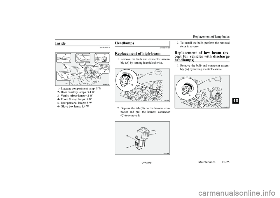
Inside
E01003403118
1- Luggage compartment lamp: 8 W
2- Door courtesy lamps: 3.4 W
3- Vanity mirror lamps* 2 W
4- Room & map lamps: 8 W
5- Rear personal lamps: 8 W
6- Glove box lamp: 1.4 W
Headlamps
E01003501199
Replacement of high-beam
1. Remove the bulb and connector assem-
bly (A) by turning it anticlockwise.
2. Depress the tab (B) on the harness con-
nector and pull the harness connector
(C) to remove it.
3. To install the bulb, perform the removal
steps in reverse.
Replacement of low beam (ex-
cept for vehicles with discharge
headlamps)
1. Remove the bulb and connector assem-
bly (A) by turning it anticlockwise.
Replacement of lamp bulbs
10-25OVWX17E1Maintenance10