sensor MITSUBISHI SPYDER 1990 Service Repair Manual
[x] Cancel search | Manufacturer: MITSUBISHI, Model Year: 1990, Model line: SPYDER, Model: MITSUBISHI SPYDER 1990Pages: 2103, PDF Size: 68.98 MB
Page 474 of 2103
![MITSUBISHI SPYDER 1990 Service Repair Manual E N G I N E
INSPECTION PROCEDURE 16 . ,
Acceleration shock ,
[Comment] Malfunction of the ignition systemIn cases such as the above, the cause is probably that there is an ignition leak ac MITSUBISHI SPYDER 1990 Service Repair Manual E N G I N E
INSPECTION PROCEDURE 16 . ,
Acceleration shock ,
[Comment] Malfunction of the ignition systemIn cases such as the above, the cause is probably that there is an ignition leak ac](/img/19/57345/w960_57345-473.png)
E N G I N E
INSPECTION PROCEDURE 16 . ,
Acceleration shock ,
[Comment] Malfunction of the ignition systemIn cases such as the above, the cause is probably that there is an ignition leak accompanyinglthe increase in the spark plug demand voltage durin g acceleration.Improper control of reduction stiifting.
Are diagnostic trouble codes output
NO YES
Refer to INSPECTION CHART D I A G N O S T I CTROUBLE CODES.
Check the following items.
l
Check the ignition coil, spark plugs, spark plug ca bles.
l Check for occurrence of ignition leak.
l Check the torque reduction link (wire) between the PCM and TCM.
INSPECTION PROCEDURE 17
Deceleration shock Probable cause
[Comment]Malfunction of the system is suspected.l Malfunction of ‘system
III
Are diagnostic trouble codes output
NO
YESR e f e r t o C H A R T F O R TROUBLE CODES.
SCAN TOOL Actuator test
07 motor. (Refer to PROCEDURE FOR DIAGNOSTIC TROUBLE CODES
SCAN TOOL Special function“Reset
Check trouble I
N G
TSB Revision
Check the throttle body minimum air flow.
(Refer to
SCAN TOOL SENS
07 Throttle position (Refer to NGl Check the throttle position sensor
(Refer to INSPECTION PROCEDURE 43.)
Page 476 of 2103
![MITSUBISHI SPYDER 1990 Service Repair Manual ENGINE Troubleshooting
INSPECTION PROCEDURE 20
Knocking
[Comment]l Defective knock sensorIn cases such as the above, the cause is probably t hat the detonation control is defecti MITSUBISHI SPYDER 1990 Service Repair Manual ENGINE Troubleshooting
INSPECTION PROCEDURE 20
Knocking
[Comment]l Defective knock sensorIn cases such as the above, the cause is probably t hat the detonation control is defecti](/img/19/57345/w960_57345-475.png)
ENGINE Troubleshooting
INSPECTION PROCEDURE 20
Knocking
[Comment]l Defective knock sensorIn cases such as the above, the cause is probably t hat the detonation control is defective or l
the heat value of the spark plug is inappropriate. Inappropriate value of the
YES
Are
diagnostic troublecodesRefer to INSPECTION CHART FOR DIAGNOSTIC
outputTROUBLE CODES.
NO
SCAN TOOL SENSORNG
09 Knock sensor volts (Refer toCheck the knock sensor circuit (Refer to INSPECTION
PROCEDURE FOR DIAGNOSTIC TROUBLE
OK
Check the following items. l heat ranae
l Check ‘if (water, alcohol, etc.) got into fuel.
Dieseling cause
[Comment]Fuel leakage from injectors is suspected. l
Fuel leakage from injectors
Check the injectors for fuel leakage.
R e v i s i o n
Page 477 of 2103
![MITSUBISHI SPYDER 1990 Service Repair Manual E N G I N E
INSPECTION PROCEDURE 22
Too high CO and HC concentration when idling
[Comment]Abnormal air-fuel ratio is suspected.
cause
of the air-fuel ratio control system.l MITSUBISHI SPYDER 1990 Service Repair Manual E N G I N E
INSPECTION PROCEDURE 22
Too high CO and HC concentration when idling
[Comment]Abnormal air-fuel ratio is suspected.
cause
of the air-fuel ratio control system.l](/img/19/57345/w960_57345-476.png)
E N G I N E
INSPECTION PROCEDURE 22
Too high CO and HC concentration when idling
[Comment]Abnormal air-fuel ratio is suspected.
cause
of the air-fuel ratio control system.l Deteriorated catalyst .
SCAN TOOL DTC
Are diagnostic trouble codes output Refer to INSPECTION CHART FOR DIAGNOSTICTROUBLE CODES.
NG
27 Intake air temperature sensor. (Refer to Check the intake air temperature sensor circuit.
( R e f e r t o 3 9 . ) .
N G Check the MAP sensor circuit11MAP sensor reading. (Refer to (Refer to INSPECTION PROCEDURE 40.)IOK
SCAN TOOL SENSOR READ TESTS (Data list)
83 sensor volts (rear) (Refer to l Transaxle gear range l Driving with the throttle wide open
O K :
OK
SCAN TOOL SENSOR READ TESTS (Data list)
02 sensor volts (front) (Refer to OK: 1 when suddenlv
N G Check the heated oxygensensor (rear) circuit.
(Refer to INSPECTION PROCEDURE 41.)
NG
02 sensor volts (front) (Refer to
Check the fuel pressure. (Refer to
OK
Check the following items.
l Check the injectors for operation sound.
l Check the injectors for fuel leakage.
l Check the ignition coil, spark plugs, spark plug ca bles.
l Check the compression pressure.
l Check the positive crankcase ventilation system.
l Check the evaporative emission control system.
l Check the EGR system.
NG
Check trouble symptom.
N G
Replace the three-way catalytic converter.
TSB Revisiqn
Page 479 of 2103
![MITSUBISHI SPYDER 1990 Service Repair Manual ENGINE ( N O N - T U R B O ) >
INSPECTION PROCEDURE 25
Transaxle range sensor circuit
[Comment]The transaxle range sensor inputs the condition of the selector lever, i.e. whether it MITSUBISHI SPYDER 1990 Service Repair Manual ENGINE ( N O N - T U R B O ) >
INSPECTION PROCEDURE 25
Transaxle range sensor circuit
[Comment]The transaxle range sensor inputs the condition of the selector lever, i.e. whether it](/img/19/57345/w960_57345-478.png)
ENGINE ( N O N - T U R B O ) >
INSPECTION PROCEDURE 25
Transaxle range sensor circuit
[Comment]The transaxle range sensor inputs the condition of the selector lever, i.e. whether it is in or range or in some other range, to the PCM.
The PCM controls the idle air control motor based o n this input.Improper connector contact, open circuit
Check the transaxle range sensor. (Refer to GROUP On-vehicle Service.) Replace.
lDisconnect the connector,and measure atthe harness
A-l
OK
Check trouble symptom.
OK
Replace the PCM.
Check harness wire betweenN G
PCM transaxle rangesensor connector.
O K
Replace the PCM.
,
INSPECTION PROCEDURE 26
A/C switch and A/C compressor clutch relay system
motor, and also operates the A/C compressor magneti c clutch.Probable cause
l Malfunction of A/C control l Malfunction of A/C switch Improper connector open short-circuited harness wire
l Malfunction of PCM
NG
OKCheck the A/C compressor clutch relay.
Measure at the PCM
l
(Refer to GROUP 55 On-vehicle Service.)
Disconnect the connector, and measure at the harnes s
Replace
Check the
system. (Refer to GROUP 55
side.lVoltage between 64 and ground, and 38 and ground(Ignition switch: ON)
(A/C switch: ON)
OK: Battery positive voltage
l Connect a jumper wire between 64 and ground.
(Ignition switch: ON)
(A/C switch: ON)
OK: A/C compressor clutch turns ON.
OK1NG RepairA-l 06,A-l 07
OK
Check trouble symptom.
Replace the PCM.
NG
TSB Revision
Page 481 of 2103
ENGINE (NON-TURBO)>
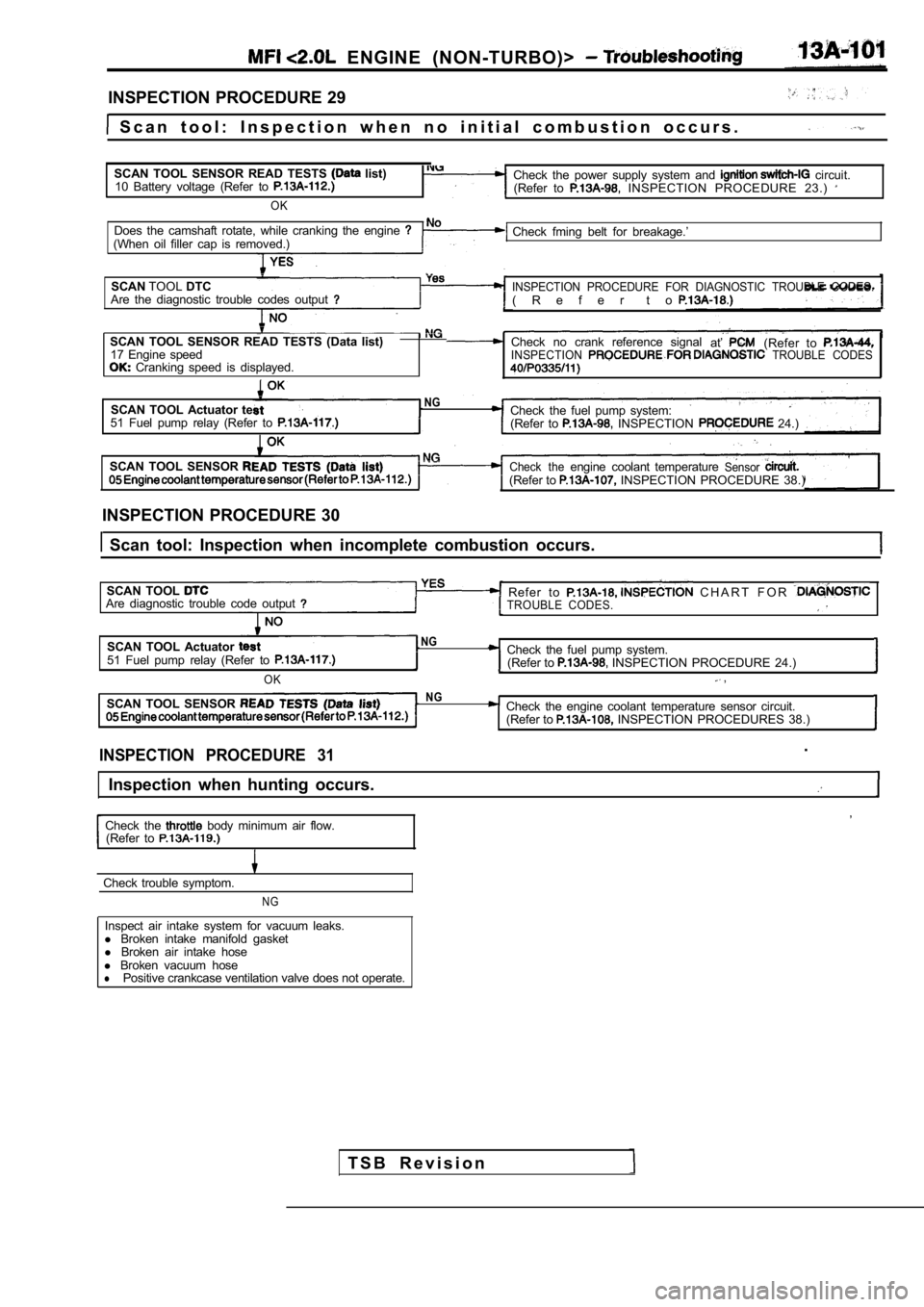
INSPECTION PROCEDURE 29
S c a n t o o l : I n s p e c t i o n w h e n n o i n i t i a l c o m b u s t i o n oc c u r s .
SCAN TOOL SENSOR READ TESTS
list)
10 Battery voltage (Refer to
OK
Check the power supply system and circuit.
(Refer to INSPECTION PROCEDURE 23.)
Does the camshaft rotate, while cranking the engine (When oil filler cap is removed.) Check fming belt for breakage.’
SCAN TOOLDTC
INSPECTION PROCEDURE FOR DIAGNOSTIC TROUBLE CODES.Are the diagnostic trouble codes output( R e f e r t o
SCAN TOOL SENSOR READ TESTS (Data list) Check no crank reference signal
at’(Refer to 17 Engine speedINSPECTION TROUBLE CODES Cranking speed is displayed.
SCAN TOOL Actuator teNGCheck the fuel pump system:51 Fuel pump relay (Refer to (Refer to INSPECTION 24.)
SCAN TOOL SENSOR
Check theengine coolant temperatureSensor(Refer to INSPECTION PROCEDURE 38.)
INSPECTION PROCEDURE 30
Scan tool: Inspection when incomplete combustion o ccurs.
SCAN TOOL
Refer to C H A R T F O R Are diagnostic trouble code outputTROUBLE CODES.
SCAN TOOL Actuator NG
51 Fuel pump relay (Refer to Check the fuel pump system. (Refer to INSPECTION PROCEDURE 24.)
OK ,
SCAN TOOL SENSOR NGCheck the engine coolant temperature sensor circuit .
(Refer to INSPECTION PROCEDURES 38.)
INSPECTION PROCEDURE 31.
Inspection when hunting occurs.
,
Check the body minimum air flow.
(Refer to
Check trouble symptom.
NG
Inspect air intake system for vacuum leaks.
l Broken intake manifold gasket
l Broken air intake hose
l Broken vacuum hose
lPositive crankcase ventilation valve does not opera te.
T S B R e v i s i o n
Page 482 of 2103
ENGINE (NON-TURBO)>
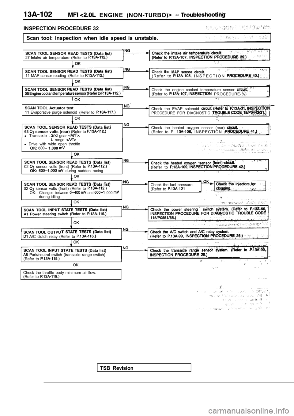
INSPECTION PROCEDURE 32Scan tool: Inspection when idle speed is unstable.
SCAN TOOL SENSOR READ TESTS (Data list)
27
air temperature (Refer to . .
SCAN TOOL SENSOR 11 MAP sensor reading (Refer to
NG CheckMAP sensor circuit.( R e f e r t o I N S P E C T I O N
SCAN TOOL SENSOR NGCheck the engine coolant temperature sensor (Refer to PROCEDURE-%)
SCAN TOOL Actuator test11 Evaporative purge solenoid (Refer toCheck the EVAP solenoid PROCEDURE FOR DIAGNOSTIC
SCAN TOOL SENSOR READ TESTS (Data list)
63 sensor volts (rear) (Refer to l Transaxle gear
Check the heated oxygen sensor (rear) (Refer to P. I N S P E C T I O N . . range l Drive with wide open throttle
OK: 1,000
SCAN TOOL SENSOR READ TESTS (Data list)NG
02 sensor volts (front) (Refer to Check the heated oxygen ‘sensor
OK: during sudden racing (Refer to
SCAN TOOL SENSOR READ TESTS (Data list)
02 sensor volts (front) (Refer to Changes between and ,000 OK:during idling Check the fuel pressure.
(Refer to
SCAN TOOL OUTPU A/C clutch relay (Refer to
SCAN TOOL INPUT STATE TESTS (Data list) Park/neutral switch (transaxle range switch)
(Refer to
OK
Check the throffle body minimum air flow.
(Refer to
. . .
. .
TSB Revision
Page 483 of 2103
(NON-TURBO)> .
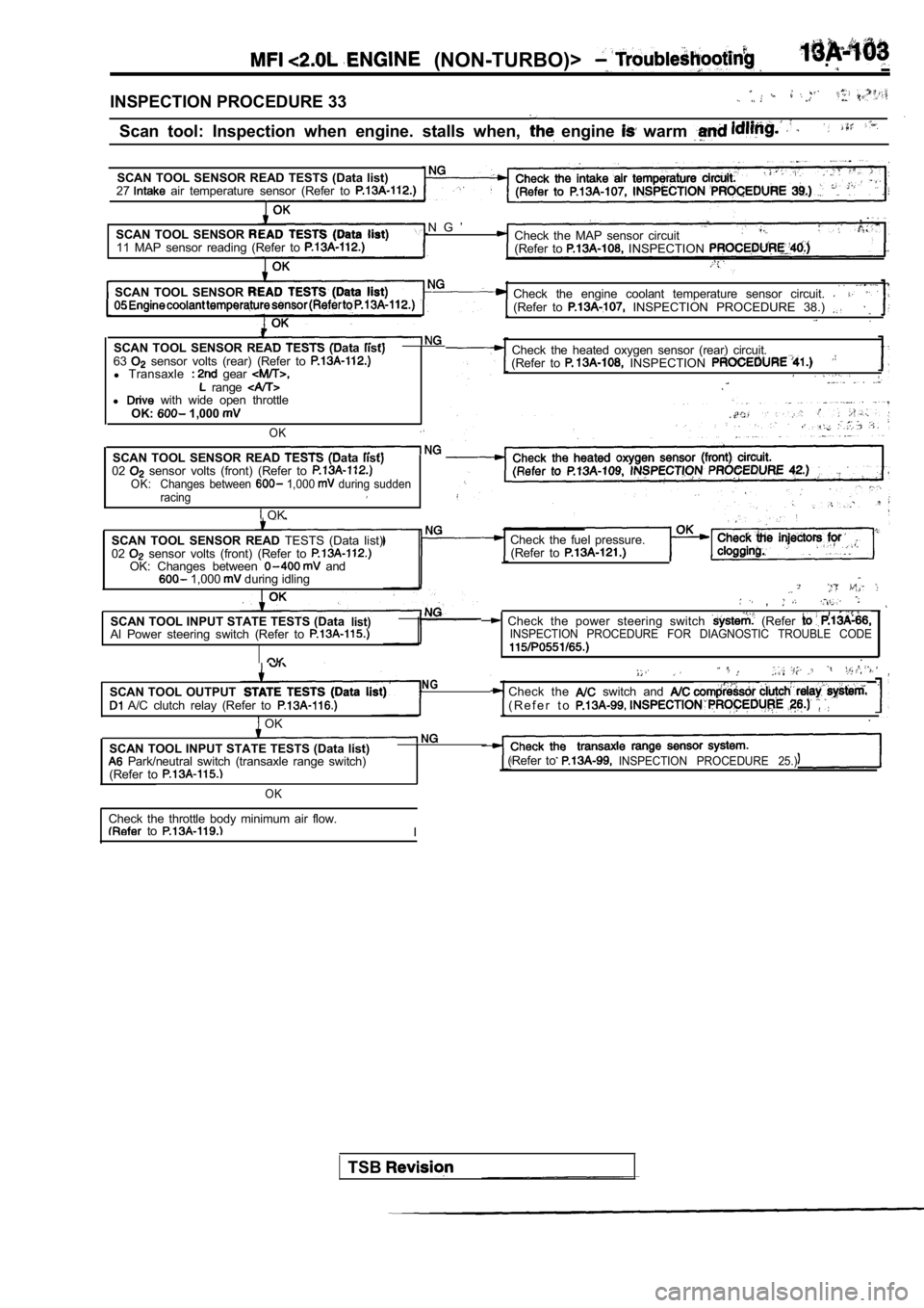
INSPECTION PROCEDURE 33
Scan tool: Inspection when engine. stalls when, engine warm
SCAN TOOL SENSOR READ TESTS (Data list)
27 air temperature sensor (Refer to
.
SCAN TOOL SENSOR N G ’ Check the MAP sensor circuit
11 MAP sensor reading (Refer to
(Refer to INSPECTION
SCAN TOOL SENSOR Check the engine coolant temperature sensor circuit . (Refer to INSPECTION PROCEDURE 38.) .
SCAN TOOL SENSOR READ TESTS (Data list)
63 sensor volts (rear) (Refer to l Transaxle gear range l with wide open throttle
OK: 1,000
OK
SCAN TOOL SENSOR READ TESTS (Data list)
02 sensor volts (front) (Refer to OK: Changes between 1,000 during sudden
racing
OK Check the heated oxygen sensor (rear) circuit.
(Refer to
INSPECTION ,
SCAN TOOL SENSOR READ TESTS (Data list)
02 sensor volts (front) (Refer to OK: Changes between and 1,000 during idling
SCAN TOOL INPUT STATE TESTS (Data
list)Al Power steering switch (Refer to
Check the fuel pressure. (Refer to
,
Check the power steering switch (Refer INSPECTION PROCEDURE FOR DIAGNOSTIC TROUBLE CODE
.
SCAN TOOL OUTPUT
A/C clutch relay (Refer to
OK
NGCheck the switch and ( R e f e r t o .
SCAN TOOL INPUT STATE TESTS (Data list) Park/neutral switch (transaxle range switch)
(Refer to (Refer toINSPECTION PROCEDURE 25.)
OK
Check the throttle body minimum air flow. to I
TSB
Page 484 of 2103
ENGINE (NON-TURBO)> Troubleshooting
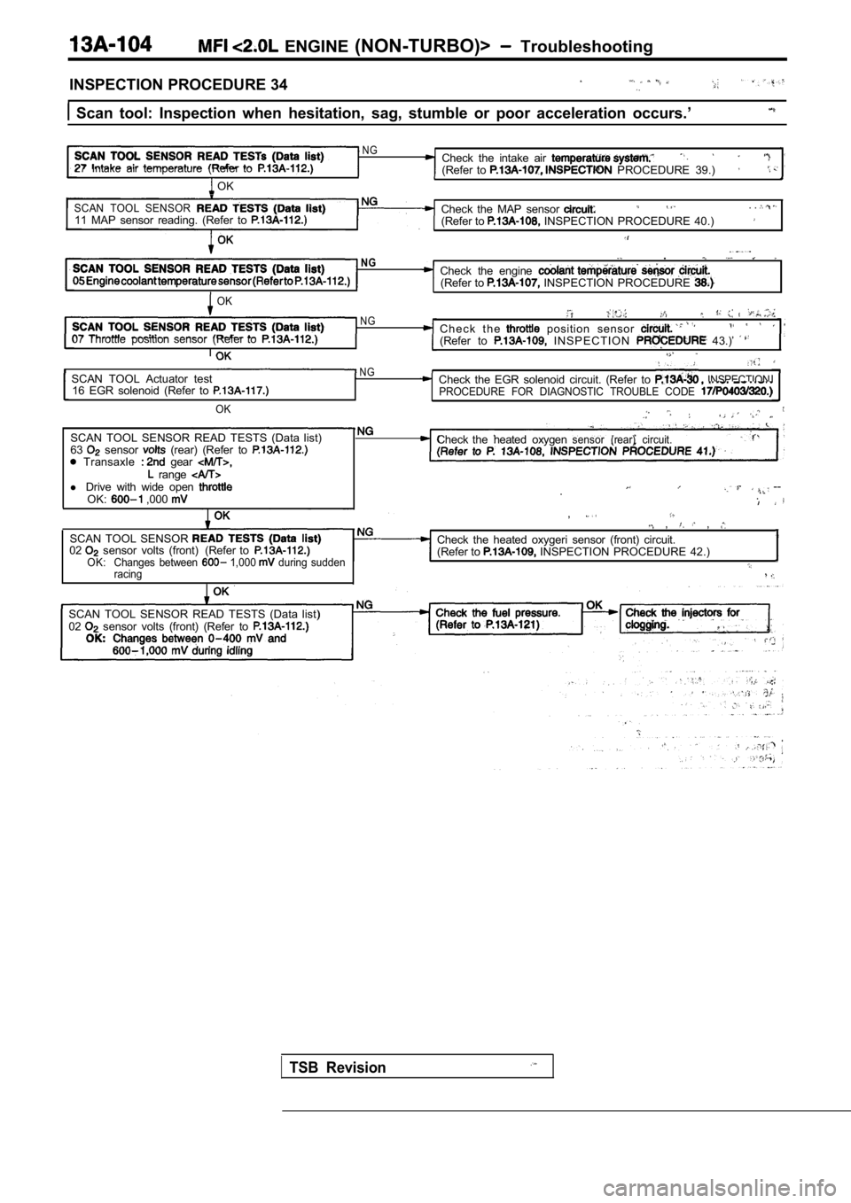
INSPECTION PROCEDURE 34
Scan tool: Inspection when hesitation, sag, stumbl e or poor acceleration occurs.’
N G
27 Intakeair temperature (Refer toCheck the intake air (Refer to PROCEDURE 39.)
OK
SCAN TOOL SENSOR11 MAP sensor reading. (Refer to Check the MAP sensor . .
(Refer to INSPECTION PROCEDURE 40.)
NG.
Check the engine (Refer to INSPECTION PROCEDURE
OK
N G
07 Throttle position sensor (Refer toC h e c k t h e position sensor (Refer to I N S P E C T I O N 43.)’ I
SCAN TOOL Actuator testN GINSPECTION16 EGR solenoid (Refer to
OK
SCAN TOOL SENSOR READ TESTS (Data list)
63 sensor (rear) (Refer to Transaxle gear range l Drive with wide open OK: ,000
Check the EGR solenoid circuit. (Refer to PROCEDURE FOR DIAGNOSTIC TROUBLE CODE
Check thesensor circuit.heated oxygen(rear)
. --.
SCAN TOOL SENSOR 02 sensor volts (front) (Refer toOK: Changes between 1,000 during sudden
racing
, , ,
Check the heated oxygeri sensor (front) circuit.
(Refer to INSPECTION PROCEDURE 42.)
SCAN TOOL SENSOR READ TESTS (Data list)
02 sensor volts (front) (Refer to
TSB Revision
Page 485 of 2103
E N G I N E
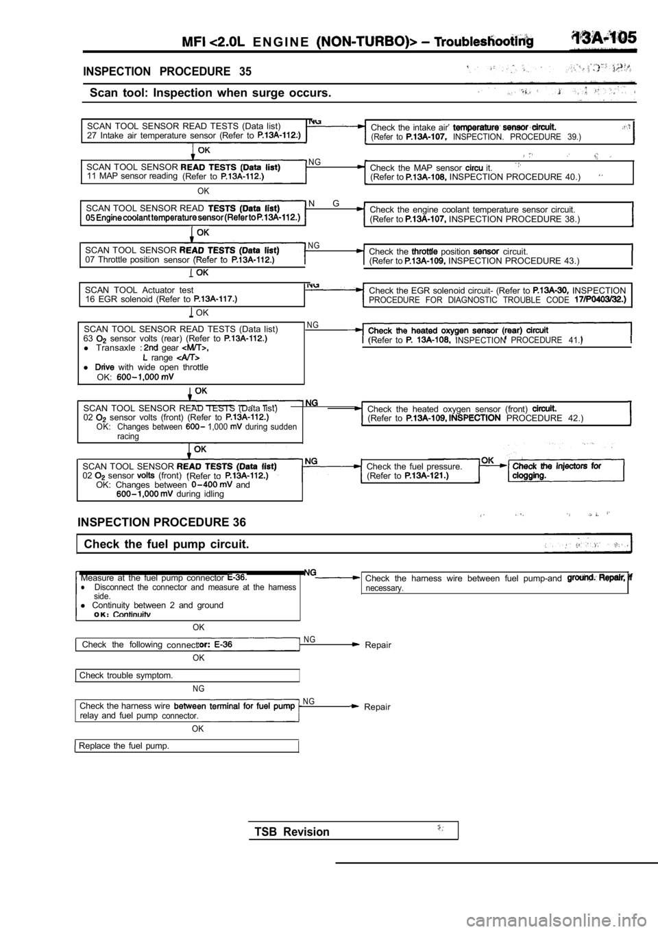
INSPECTION PROCEDURE 35
Scan tool: Inspection when surge occurs.
SCAN TOOL SENSOR READ TESTS (Data list)
27 Intake air temperature sensor (Refer to
Check the intake air’ (Refer to INSPECTION. PROCEDURE 39.)
SCAN TOOL SENSOR 11 MAP sensor reading (Refer to
OK NG
Check the MAP sensor it.(Refer to INSPECTION PROCEDURE 40.)
SCAN TOOL SENSOR READ
N GCheck the engine coolant temperature sensor circuit
.
(Refer to INSPECTION PROCEDURE 38.)
SCAN TOOL SENSOR NGCheck the position circuit.
07 Throttle position sensor (Refer to(Refer to INSPECTION PROCEDURE 43.)
SCAN TOOL Actuator test
16 EGR solenoid (Refer to
OK Check the EGR solenoid circuit- (Refer to
INSPECTIONPROCEDURE FOR DIAGNOSTIC TROUBLE CODE
SCAN TOOL SENSOR READ TESTS (Data list)
63 sensor volts (rear) (Refer to l Transaxle gear range l with wide open throttle
OK:
NG
(Refer to INSPECTION PROCEDURE 41.)
SCAN TOOL SENSOR READ TESTS (Data list)
02 sensor volts (front) (Refer to OK: Changes between 1,000 during sudden
racing
Check the heated oxygen sensor (front) (Refer to PROCEDURE 42.)
SCAN TOOL SENSOR 02 sensor (front) (Refer toOK: Changes between and during idling Check the fuel pressure.
(Refer to
INSPECTION PROCEDURE 36
Check the fuel pump circuit.
Measure at the fuel pump connector
Check the harness wire between fuel pump-and lDisconnect the connector and measure at the harness necessary.
side.
l Continuity between 2 and ground
O K :
OK
Check the following connectNG Repair
OK
Check trouble symptom.
NG
Check the harness wirerelay and fuel pumpconnector.
OK
N G Repair
Replace the fuel pump.
TSB Revision
Page 487 of 2103
E N G I N E
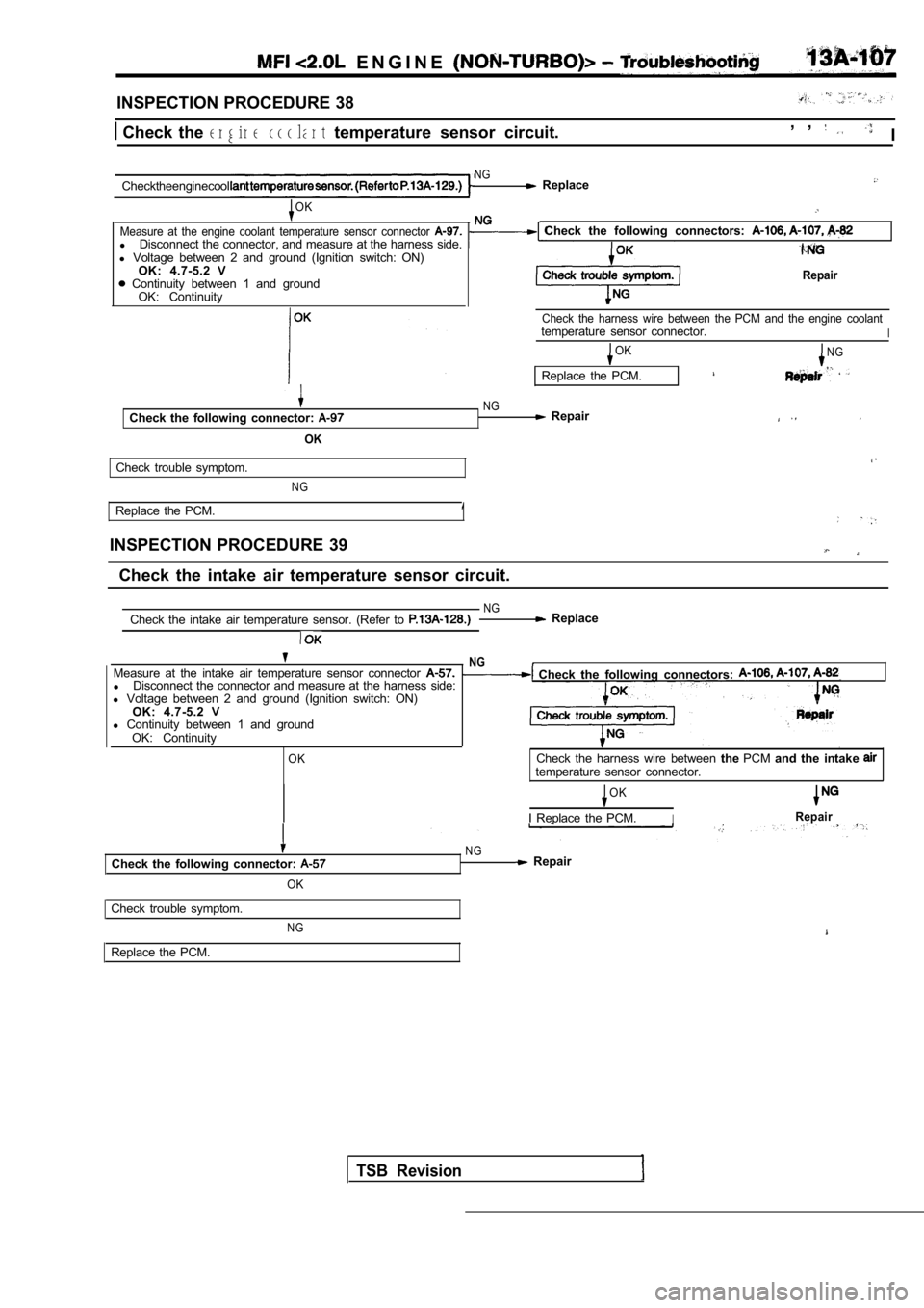
INSPECTION PROCEDURE 38
Check the engine coolant temperature sensor circuit. , , I
Checktheenginecool
NG Replace
OK
Measure at the engine coolant temperature sensor co nnector
lDisconnect the connector, and measure at the harnes s side.
l Voltage between 2 and ground (Ignition switch: ON)
OK: 4.7-5.2
Continuity between 1 and ground OK: Continuity
Check the following connectors:
Repair
Check the harness wire between the PCM and the engi ne coolanttemperature sensor connector.I
Check the following connector:
OK
OKN G
Replace the PCM.
NG Repair
Check trouble symptom.
N G
Replace the PCM.
INSPECTION PROCEDURE 391
Check the intake air temperature sensor circuit.
NGCheck the intake air temperature sensor. (Refer to Replace
NGMeasure at the intake air temperature sensor connec tor Check the following connectors: lDisconnect the connector and measure at the harness side:
l Voltage between 2 and ground (Ignition switch: ON)
OK: 4.7-5.2
l Continuity between 1 and ground
OK: Continuity
OKCheck the harness wire between thePCM and the intake temperature sensor connector.
OK
I Replace the PCM.IRepair
Check the following connector:
OK
NG Repair
Check trouble symptom.
Replace the PCM.
NG
TSB Revision