heater MITSUBISHI SPYDER 1990 Service User Guide
[x] Cancel search | Manufacturer: MITSUBISHI, Model Year: 1990, Model line: SPYDER, Model: MITSUBISHI SPYDER 1990Pages: 2103, PDF Size: 68.98 MB
Page 449 of 2103
![MITSUBISHI SPYDER 1990 Service User Guide (NON-TURBO)>
Scan tool 126
Code General scan tool Downstream Shorted to
No. 38Voltage
21
[Comment]l Heated oxygen sensor failedBackgroundlDownstream heated oxygen sensor requires](/img/19/57345/w960_57345-448.png "MITSUBISHI SPYDER 1990 Service User Guide (NON-TURBO)>
Scan tool 126
Code General scan tool Downstream Shorted to
No. 38Voltage
21
[Comment]l Heated oxygen sensor failedBackgroundlDownstream heated oxygen sensor requires")
(NON-TURBO)>
Scan tool 126
Code General scan tool Downstream Shorted to
No. 38Voltage
21
[Comment]l Heated oxygen sensor failedBackgroundlDownstream heated oxygen sensor requires a heater c ircuit for proper operation.l harness and connectors
l
The heater circuit is supplied with battery voltage through the relay relay).l .
lA failure in the sensors heater circuit prevents it
from providing accurate data to the lIf the PCM monitors more than 1.2 volts, the sensor has shorted to heater circuit voltage.Range of Checkl Two or more minutes after the engine startsl Engine coolant temperature: or moreSet Conditionl Heated oxygen sensor output voltage is more than 1. 2 for 3 seconds.
NGCheck the heated oxygen sensor (rear). (Refer to R e p l a c e
OKNGCheck the following Repair
OK
Check trouble symptom.
NG
Check the harness wire between the PCM and the hea ted NG
sensor (rear) connector.
OK
Replace the PCM.
Scan tool 128
Code General scan tool Closed Loop Temperature
No.
17
[Comment]l Thermostat fully openBackgroundl Engine coolant temperature sensorl The fuel control system remains in open loop due to low engine lEngine coolant temperature sensor lThis DTC will be stored if engine temperature remains for 10 minutesimproperly connected
of operation and no engine coolant temperature sens or code has been set.
l PCM failed,
Range of Check
l Engine: running ,Set ConditionlEngine coolant temperature does not exceed after 10 minutes have passed ,
since starting the engine.
,
NGCheck the thermostat. (Refer to GROUP 14 Thermostat.) Replace
OKNG Replace
Check the following connectors:NG Repair
Check trouble symptom.
temperature
sensor connector. OK
TSB Revision
Page 527 of 2103
E N G I N E ( T U R B O )
AND
ENGINE>
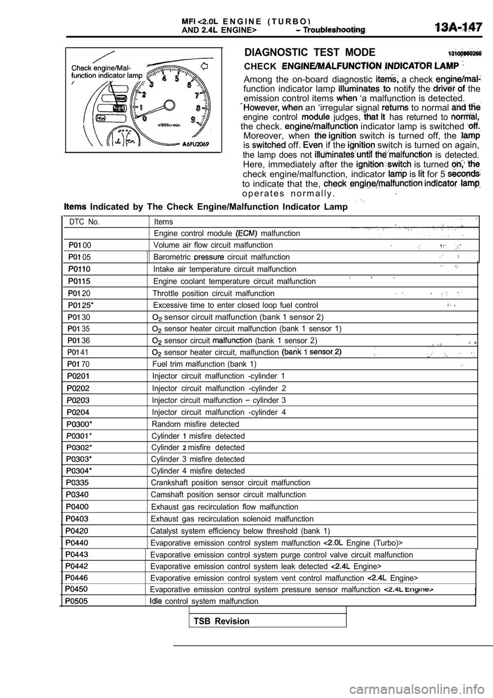
DIAGNOSTIC TEST MODE
CHECK
Among the on-board diagnostic a check
function indicator lamp notify the the
emission control items
‘a malfunction is detected.
an ‘irregular signal to normal
engine control judges, has returned to
the check. indicator lamp is switched
Moreover, when switch is turned off, the
is off. if the switch is turned on again,
the lamp does not is detected.
Here, immediately after the is turned
check engine/malfunction, indicator is for 5
to indicate that the,
o p e r a t e s n o r m a l l y .
Indicated by The Check Engine/Malfunction Indicato r Lamp
00
05
20
30
35
36
41
70
Items
Engine control module
malfunction
Volume air flow circuit malfunction
Barometric
circuit malfunction
Intake air temperature circuit malfunction
Engine coolant temperature circuit malfunction
Throttle position circuit malfunction
Excessive time to enter closed loop fuel control
sensor circuit malfunction (bank 1 sensor 2)
sensor heater circuit malfunction (bank 1 sensor 1 )
sensor circuit (bank 1 sensor 2).
sensor heater circuit, malfunction 1
Fuel trim malfunction (bank 1)
Injector circuit malfunction -cylinder 1
Injector circuit malfunction -cylinder 2
Injector circuit malfunction
cylinder 3
Injector circuit malfunction -cylinder 4
Random misfire detected
Cylinder
misfire detected
Cylinder
2misfire detected
Cylinder 3 misfire detected Cylinder 4 misfire detected
Crankshaft position sensor circuit malfunction
Camshaft position sensor circuit malfunction
Exhaust gas recirculation flow malfunction
Exhaust gas recirculation solenoid malfunction
Catalyst system efficiency below threshold (bank 1) Evaporative emission control system malfunction
Engine (Turbo)>
Evaporative emission control system purge control v alve circuit malfunction
Evaporative emission control system leak detected
Engine>
Evaporative emission control system vent control ma lfunction
Engine>
Evaporative emission control system pressure sensor malfunction
control system malfunction
DTC No.
TSB Revision
Page 535 of 2103
ENGINE (TURBO)
AND
ENGINE> Troubleshooting .
6. Other monitoring
lMisfire
l Evaporative emission control system
l Idle air control system
l Manifold differential pressure sensor
lExcessive time to enter closed loop fuel control
l Throttle position sensor
l Barometric pressure sensor
Intake air temperature sensor
l Serial communication link
l Crankshaft position sensor
l Camshaft position sensor
Volume air flow sensor
Test conditions/procedure
l Engine coolant temperature sensor
l Closed throttle position switch
l Generator terminal circuit
l sensor circuit
l sensor heater circuit
Turbocharger waste gate solenoid
l EGR solenoid
lEvaporative emission purge solenoid
l Evaporativeemissionventilation
solenoid Engine>
l Fuel pressure solenoid
lInjector circuit
1. All of the following conditions should be satisf ied when the drive test is carried out.
(1) Engine coolant temperature:
or higher (when engine is fully warmed up)
(2) Outside air temperature:
or higher
(3)
condition:
lSelector lever position: range
l Overdrive switch: ON
lPower/economy changeover switch: Power
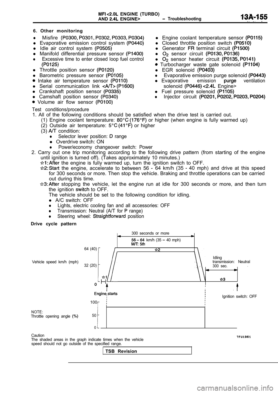
2. Carry out one trip monitoring according to the f ollowing drive pattern (from starting of the engine
until ignition is turned off). (Takes approximately 10 minutes.)
the engine is fully warmed up, turn the ignition s witch to OFF.
the engine, accelerate to between 56 64 km/h (35 40 mph) and drive at this speed
for 300 seconds or more. Then stop the vehicle. Bra king and throttle operations can be carried
out during this time.
stopping the vehicle, let the engine run at idle f or 300 seconds or more, and then turn
the ignition
to OFF.
The vehicle should be set to the following conditio n for idling.
l A/C switch: OFF
lLights, electric cooling fan and all accessories: O FF
lTransmission: Neutral (A/T for range)
lSteering wheel: position
Drive cycle pattern
300 seconds or more
km/h (35 40 mph)
64 (40)
Idling
Vehicle speed km/h (mph) transmission: Neutral
32 (20)
300 seo.
,
Ignition switch: OFF
100
NOTE:Throttle opening angle 50
0
Caution
The shaded areas in the graph indicate times when t he vehicle
speed should not go outside of the specified range.
TSB Revision
Page 539 of 2103
ENGINE (TURBO)
AND
ENGINE> Troubleshooting
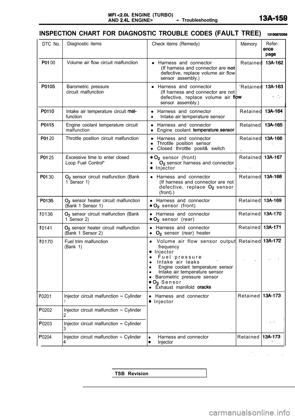
INSPECTION CHART FOR DIAGNOSTIC TROUBLE CODES (FAULT TREE)
DTC No.Diagnostic items Check items (Remedy) MemoryRefer-
,
00Volume air flow circuit malfunctionl Harness and connector
R e t a i n e d
(If harness and connector are not
defective, replace volume air flow
sensor assembly.)
Barometric pressurel Harness and connector
‘ R e t a i n e d
circuit malfunction(If harness and connector are not
defective, replace volume air ,
sensor assembly.)
Intake air temperature circuit l Harness and connector R e t a i n e d
functionlIntake air temperature sensor
Engine coolant temperature circuitl Harness and connector
Retained
malfunctionl Engine coolant
20Throttle position circuit malfunctionl Harness and connector R e t a i n e dl Throttle position sensor
l Closed throttle posit& switch
25
30
‘0136
‘0141
‘0170
Excessive time to enter closed sensor (front) R e t a i n e d
Loop Fuel Control*l sensor harness and connector
I n j e c t o r
sensor circuit malfunction (Bankl
Harness and connector R e t a i n e d
1 Sensor 1)(If harness and connector are not
d e f e c t i v e , r e p l a c e
s e n s o r
(front).)
sensor heater circuit malfunctionl Harness and connector R e t a i n e d
(Bank 1 Sensor 1) sensor (front)
sensor circuit malfunction (Bankl Harness and connector R e t a i n e d
1 Sensor 2) sensor (rear)
sensor heater circuit malfunctionl
Harness and connector R e t a i n e d
(Bank 1 Sensor 2)l sensor (rear) heater
Fuel trim malfunctionl
V o l u m e a i r f l o w s e n s o r o u t p u t R e t a i n e d
(Bank 1)frequency
I n j e c t o r
l F u e l p r e s s u r e
l I n t a k e a i r l e a k s
lEngine coolant temperature sensorlIntake air temperature sensor
l Barometric pressure sensor
S e n s o r
l Exhaust manifold
‘0201 Injector circuit malfunction Cylinderl
Harness and connector R e t a i n e d
1 I n j e c t o r
‘0202Injector circuit malfunction Cylinder
2
‘0203Injector circuit malfunction Cylinder.
3
‘0204Injector circuit malfunction CylinderlHarness and connector R e t a i n e d
4Injector
TSB Revision
Page 549 of 2103
![MITSUBISHI SPYDER 1990 Service User Guide ENGINE (TURBO)
AND ENGINE> Troubleshooting
Code No. 35 (Heated Oxygen) Sensor Heater Circuit Probable cause
Malfunction (Bank 1 Sensor 1)
[Comment]BackgroundOpen or shorted oxy](/img/19/57345/w960_57345-548.png "MITSUBISHI SPYDER 1990 Service User Guide ENGINE (TURBO)
AND ENGINE> Troubleshooting
Code No. 35 (Heated Oxygen) Sensor Heater Circuit Probable cause
Malfunction (Bank 1 Sensor 1)
[Comment]BackgroundOpen or shorted oxy")
ENGINE (TURBO)
AND ENGINE> Troubleshooting
Code No. 35 (Heated Oxygen) Sensor Heater Circuit Probable cause
Malfunction (Bank 1 Sensor 1)
[Comment]BackgroundOpen or shorted oxygen sensor Open circuit in
oxygen sensor lThe engine control module checks whether the heater current Iswithin a specified range Engine module when the heater is energized.
Check Area
l Battery voltage is between 11 and 16 V.
Judgement CriterialHeater current of the front heated oxygen sensor he ater (Bank 1 Sensor 1) has continued,
to be not higher than 0.2 A or not lower than 3.5 A for 6 sec.
l Monitored only once per trip.
NG
(Refer to I,
OK ,
Measure at the
oxygen sensor
(front) connector
lDisconnectthe connector, and mea-sure at the harness side.lVoltage between and ground (Igni-tion switch: ON) Engine (Turbo)>
l Voltage between 2 and ground
(Ignition switch: ON) Engine>OK: positive voltage
Measure at the
connector l connector, and mea-sure at the harness side.
l Voltage between 60 and ground
(Ignition switch: ON)
OK: Battery positive voltage
OK
heated oxygen sensor (front) and the relay connector. if
Check trouble symptom.
Check the following connector:
NG
Replace the ECM.I
TSB Revision
Page 551 of 2103
![MITSUBISHI SPYDER 1990 Service User Guide ENGINE (TURBO)
AND ENGINE>
Code No. (Heated Oxygen) Sensor Heater Circuit
Malfunction (Bank 1 Sensor 2)
[Comment]
Background
lThe engine control module checks whether the heater curre](/img/19/57345/w960_57345-550.png "MITSUBISHI SPYDER 1990 Service User Guide ENGINE (TURBO)
AND ENGINE>
Code No. (Heated Oxygen) Sensor Heater Circuit
Malfunction (Bank 1 Sensor 2)
[Comment]
Background
lThe engine control module checks whether the heater curre")
ENGINE (TURBO)
AND ENGINE>
Code No. (Heated Oxygen) Sensor Heater Circuit
Malfunction (Bank 1 Sensor 2)
[Comment]
Background
lThe engine control module checks whether the heater current is within a specified range
when the is energized.
Check Area
l Battery voltage is between 11 and 16
Judgement CriterialHeater current of the front heated oxygen sensor he ater (Bank 1 Sensor 2) has continuedto be not higher than 0.2 A or not lower than 3.5 A for sec.
l Monitored once trio.
NG Replace
(Refer to
Measure at the heated oxygen sensor
(rear) connector
lDisconnect the connector, heated oxygen sensor (rear) and the relay connector. Repair, if sure at the harness side.IlVoltage between ground (Igni-tion switch: ON)
OK: Battery positive voltage
Measure at the ECM connector
OK
Check the following connector:NG
cause
lOpenorshorted oxygen sensor in oxygen sensor heater’
l Engine control module failed
NG Check the following connector: Repair
OK
Check trouble symptom.
Check trouble symptom. ECM and the heated
oxygen sensor
(rear) connector. Repair, necessary.,
NG
Replace the ECM.
TSB RevisionI
Page 628 of 2103
ENGINE (TURBO)
AND ENGINE> Troubleshooting
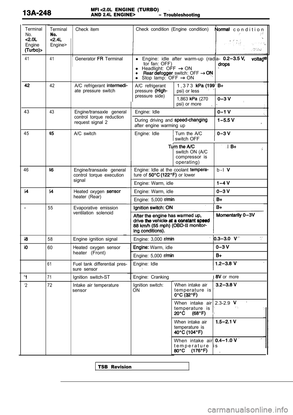
TerminalCheck itemCheck condition (Engine condition) c o n d i t i o n
No.
Engine>
Terminal
No.
Engine
41 41Generator Terminall Engine: idle after warm-up (radia-
tor fan: OFF)
l Headlight: OFF ONl switch: OFF l Stop lamp: OFF ON
A/C refrigerant A/C refrigerant1 , 3 7 3
ate pressure switch
pressurepsi) or less
pressure side)
1,863 (270
psi) or more
Engine/transaxle general
control torque reduction
request signal 2 Engine: Idle
During driving and
after engine warming up
Engine: Idle
Turn the A/C
,
switch OFF
switch ON (A/C
compressor is
operating)
Engine: Idle at the coolant b - l
ture of or lower
Engine: Warm, idle
Engine: Warm, idle
Engine: 5,000
the at a constant speed
Engine: 3,000
Warm, idle
Engine: 5,000
Engine: Idle
I
Engine: CrankingIor more
Ignition switch:
ON When intake air
t e m p e r a t u r e i s
When intake air 2.3-2.9
t e m p e r a t u r e i s
When intake air
temperature is
When intake air
t e m p e r a t u r e i s
.
42
4343
A/C switch45
46Engine/transaxle general
control torque execution
signal
Heated oxygen
heater (Rear)
55Evaporative emission
ventilation solenoid
58Engine ignition signal
Heated oxygen sensor
heater (Front)
60
61Fuel tank differential pres-
sure sensor
71Ignition switch-ST
Intake air temperature
sensor
‘272
TSB Revision
Page 632 of 2103
ENGINE (TURBO)
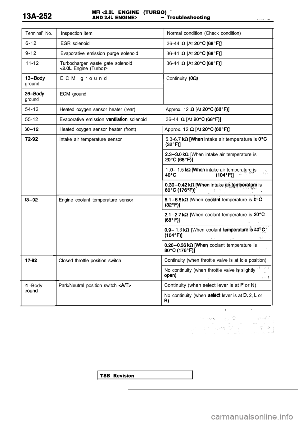
AND ENGINE> Troubleshooting
Terminal’ No.
6 - 1 2
9 - 1 2 11-12
ground
ground
54-12
55-12
72-92
17-92
-Body
Inspection item
EGR solenoid Normal condition (Check condition)
36-44 [At
Evaporative emission purge solenoid
Turbocharger waste gate solenoid
Engine (Turbo)>
36-44 [At
36-44 [At
E C M g r o u n dContinuity
ECM ground
Heated oxygen sensor heater (rear)
Evaporative emission
solenoid Approx. 12
[At
36-44 [At
Heated oxygen sensor heater (front) Approx. 12 [At
Intake air temperature sensor5.3-6.7 intake air temperature is
[When intake air temperature is
1 1.5 intake air temperature is
Engine coolant temperature sensor
intake is
.
[When temperature is
[When coolant temperature is
1.3 [When coolant
coolant temperature is
TSB Revision
Closed throttle position switch
Continuity (when throttle valve is at idle position
)
No continuity (when throttle valve
slightly
Park/Neutral position switch Continuity (when select lever is at or N)
No continuity (when lever is at 2, or
Page 671 of 2103
E N G I N E ( T U R B O )
AND ENGINE>
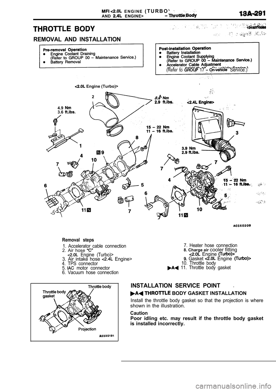
REMOVAL AND INSTALLATION
(Refer to 17 Service.)
Engine (Turbo)>
2 A . .
4.93.6
Removal steps
1. Accelerator cable connection2. Air hose Engine (Turbo)>3. Air intake hose Engine>4. TPS connector
5. motor connector
6. Vacuum hose connection 7. Heater hose connection
8. Charge air
cooler fitting Engine Gasket Engine10. Throttle body 11. Throttle body gasket
INSTALLATION SERVICE POINT.
BODY GASKET INSTALLATION
Install the throttle body gasket so that the projec tion is where
shown in the illustration.
Caution
Poor idling etc. may result if the throttle body ga sket
is installed incorrectly.
Page 694 of 2103
E N G I N E C O O L I N G
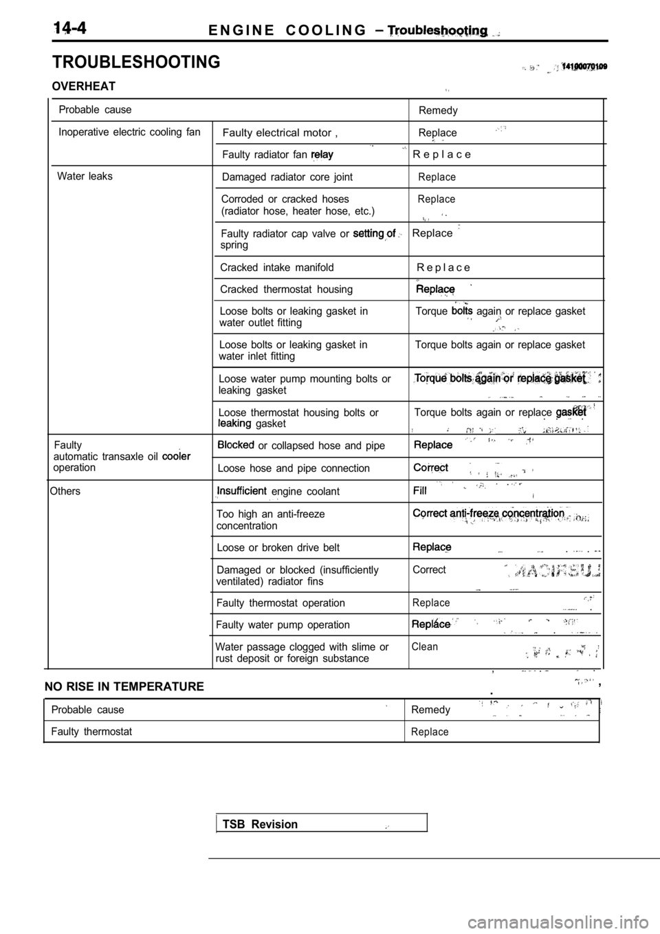
TROUBLESHOOTING
OVERHEAT
Probable cause
Inoperative electric cooling fan
Water leaks
Faulty electrical motor ,
Faulty radiator fan
Damaged radiator core joint
Corroded or cracked hoses
(radiator hose, heater hose, etc.)
Remedy
Replace
R e p l a c e
Replace
Replace
.
Faulty radiator cap valve or Replace
spring
Cracked intake manifold
Cracked thermostat housing
R e p l a c e
Loose bolts or leaking gasket in
water outlet fitting Torque again or replace gasket
Loose bolts or leaking gasket in
water inlet fitting Torque bolts again or replace gasket
Faulty Loose water pump mounting bolts or
leaking gasket
Loose thermostat housing bolts or
gasket
automatic transaxle oil
operation
Others
or collapsed hose and pipe
Loose hose and pipe connection
engine coolant
Too high an anti-freeze
concentration
Torque bolts again or replace . . .
.
Loose or broken drive belt
Damaged or blocked (insufficiently
ventilated) radiator fins
Faulty thermostat operation. .
Correct
Replace .
Faulty water pump operation .
Water passage clogged with slime orClean
rust deposit or foreign substance, . .
NO RISE IN TEMPERATURE
,
.
Probable cause
Faulty thermostatRemedy
Replace
TSB Revision