heater MITSUBISHI SPYDER 1990 Service Owner's Manual
[x] Cancel search | Manufacturer: MITSUBISHI, Model Year: 1990, Model line: SPYDER, Model: MITSUBISHI SPYDER 1990Pages: 2103, PDF Size: 68.98 MB
Page 710 of 2103
Water: Hose and Water Pipe EngineE N G I N E C O O L I N G ( N o n - t u r b o ) >
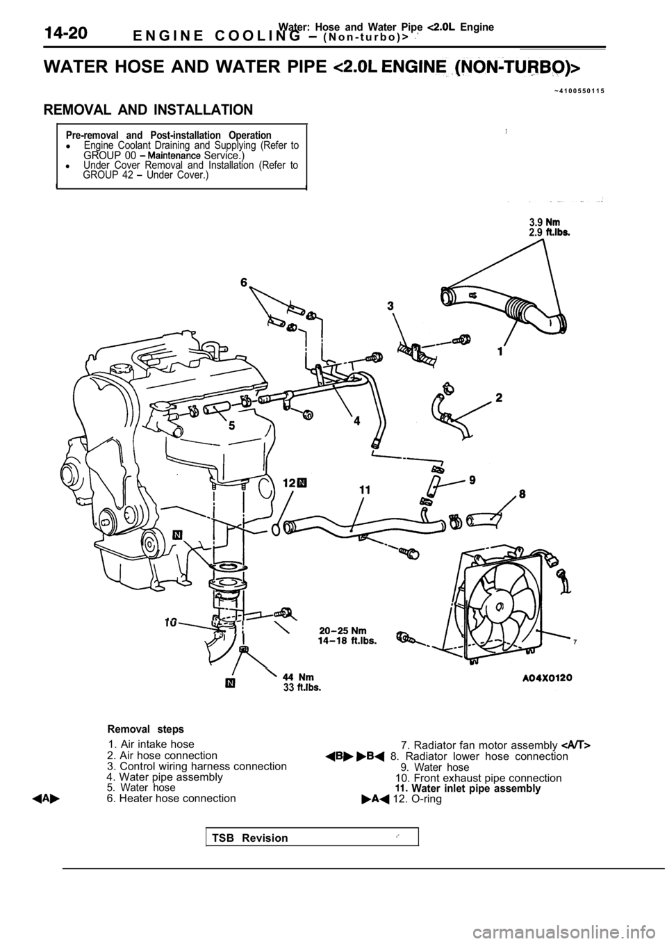
WATER HOSE AND WATER PIPE
~ 4 1 0 0 5 5 0 1 1 5
REMOVAL AND INSTALLATION
Pre-removal and Post-installation OperationlEngine Coolant Draining and Supplying (Refer toGROUP 00 Service.)lUnder Cover Removal and Installation (Refer to
GROUP 42 Under Cover.)I I
3.92.9
7
33
Removal steps
1. Air intake hose
2. Air hose connection 7. Radiator fan motor assembly
8. Radiator lower hose connection
3. Control wiring harness connection
4. Water pipe assembly
5. Water hose6. Heater hose connection
9. Water hose10. Front exhaust pipe connection Water inlet pipe assembly 12. O-ring
TSB Revision
Page 711 of 2103
WaterHose and Water Pipe Engine
ENGINE COOLING (Non-turbo)>
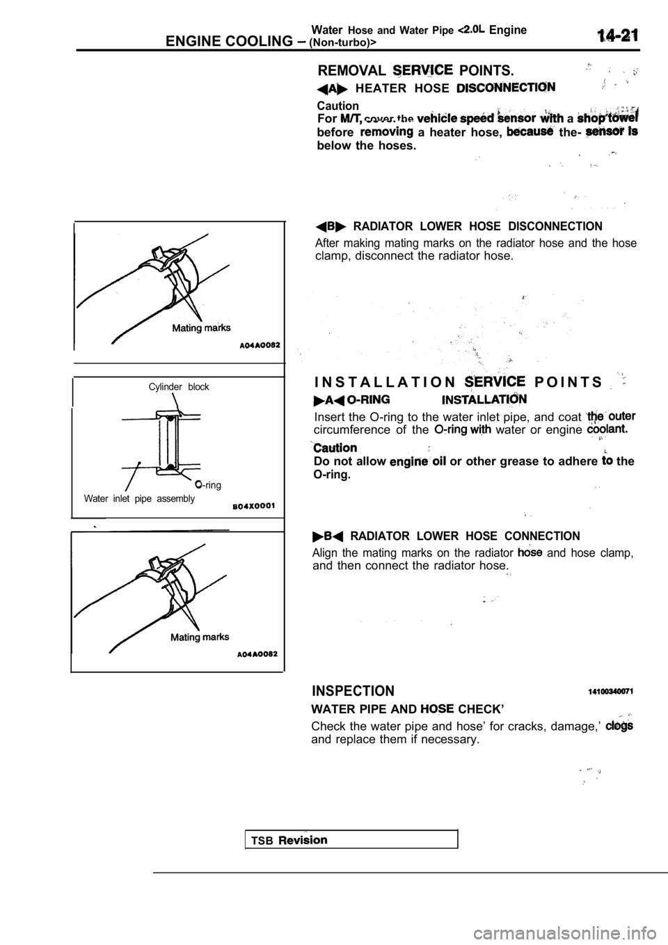
REMOVAL POINTS.
HEATER HOSE
Caution
For cover the a
before a heater hose, the-
below the hoses.
Cylinder block
O-ring
Water inlet pipe assembly
RADIATOR LOWER HOSE DISCONNECTION
After making mating marks on the radiator hose and the hose
clamp, disconnect the radiator hose.
I N S T A L L A T I O N
P O I N T S
Insert the O-ring to the water inlet pipe, and coat
circumference of the water or engine
Do not allow or other grease to adhere the
O-ring.
RADIATOR LOWER HOSE CONNECTION
Align the mating marks on the radiator and hose clamp,
and then connect the radiator hose.
INSPECTION
WATER PIPE AND CHECK’
Check the water pipe and hose’ for cracks, damage,’
and replace them if necessary.
TSB
Page 712 of 2103
Water Hose and
ENGINE COOLING and Engine>
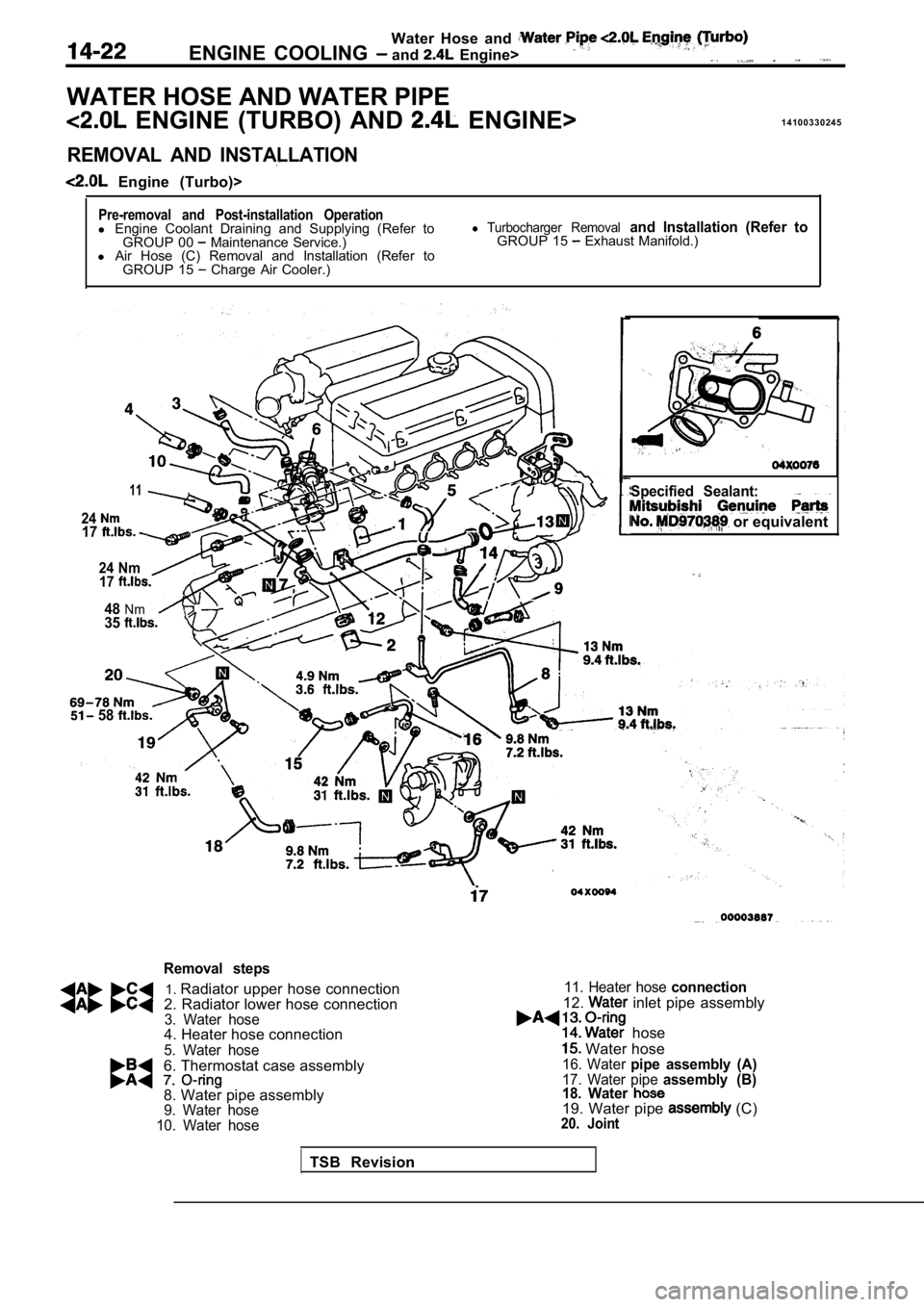
WATER HOSE AND WATER PIPE
ENGINE (TURBO) AND ENGINE>1 4 1 0 0 3 3 0 2 4 5
REMOVAL AND INSTALLATION
Engine (Turbo)>
Pre-removal and Post-installation Operationl
Engine Coolant Draining and Supplying (Refer to
GROUP 00 Maintenance Service.)
l Air Hose (C) Removal and Installation (Refer to
GROUP 15
Charge Air Cooler.)
l Turbocharger Removal and Installation (Refer toGROUP 15 Exhaust Manifold.)
11
2417
24 Nm17
48Nm35
3
Specified Sealant:
or equivalent
58
Removal steps
1. Radiator upper hose connection
2. Radiator lower hose connection
3. Water hose4. Heater hose connection
5. Water hose
6. Thermostat case assembly
8. Water pipe assembly
9. Water hose
10. Water hose
11. Heater hose connection
12. inlet pipe assembly
hose
Water hose16. Water pipe assembly (A)17. Water pipe assembly (B)
18. Water
19. Water pipe (C)20. Joint
TSB Revision
Page 713 of 2103
Water Hose and Water Pipe
ENGINE COOLING and Engine>
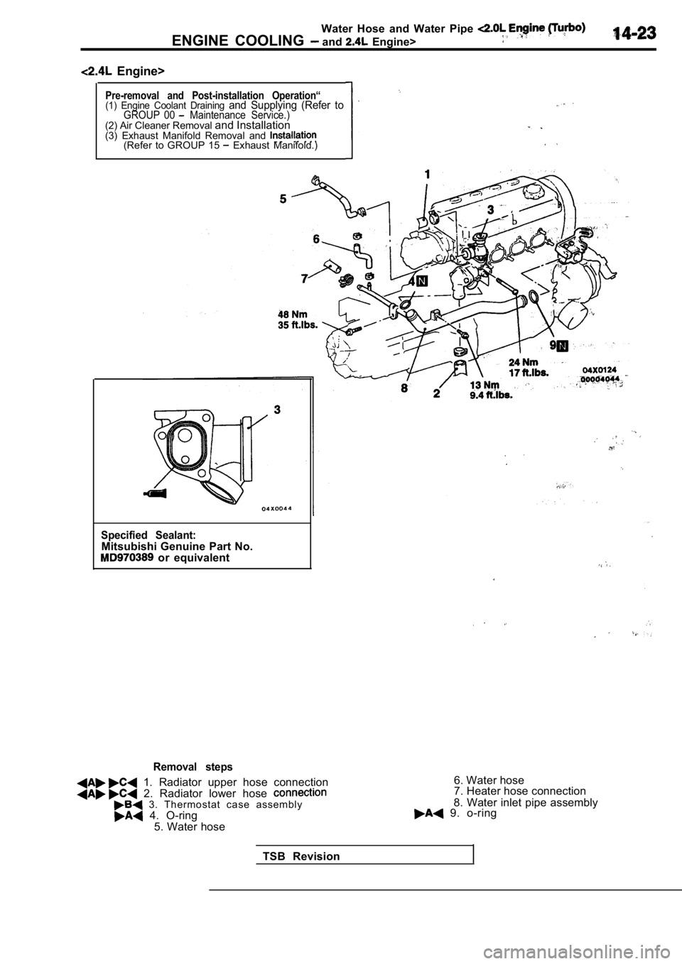
Engine>
Pre-removal and Post-installation Operation“(1) Engine Coolant Draining and Supplying (Refer toGROUP 00 Maintenance Service.)(2) Air Cleaner Removal and Installation
(3) Exhaust Manifold Removal and
(Refer to GROUP 15 Exhaust Manifold.)
Specified Sealant:Mitsubishi Genuine Part No. or equivalent
Removal steps
1. Radiator upper hose connection 2. Radiator lower hose 3. Thermostat case assembly 4. O-ring
5. Water hose 6. Water hose
7. Heater hose connection
8. Water inlet pipe assembly 9. o-ring
TSB Revision
Page 725 of 2103
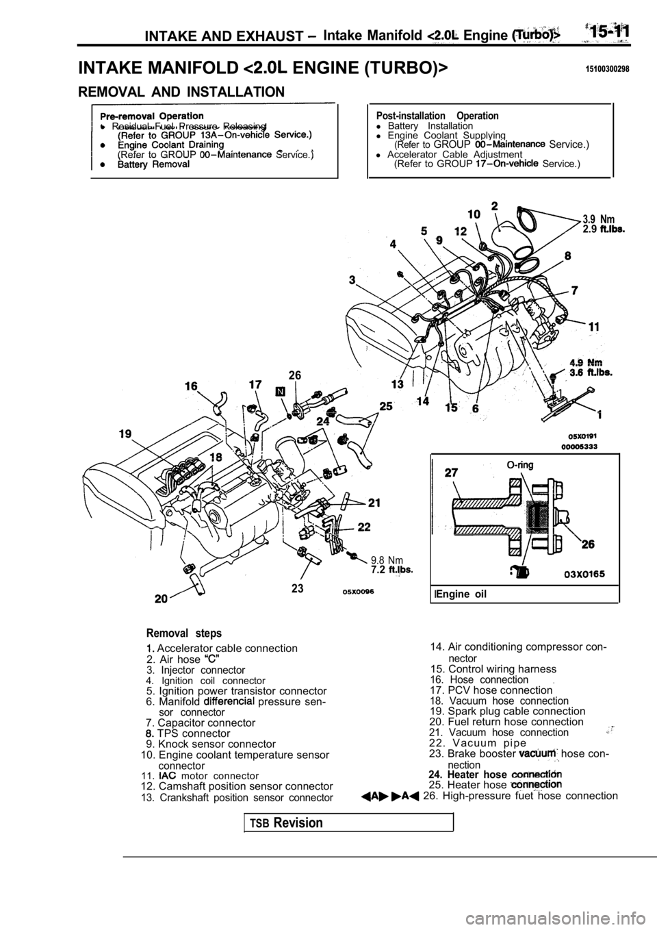
INTAKE AND EXHAUST Intake Manifold Engine
INTAKE MANIFOLD ENGINE (TURBO)>15100300298
REMOVAL AND INSTALLATION
l Residual Fuel Pressure Releasing
(Refer to GROUP
Service.)
26
Post-installation Operationl Battery Installation
l Engine Coolant Supplying
(Refer to GROUP Service.)l Accelerator Cable Adjustment
(Refer to GROUP Service.)
3.9 Nm2.9
9.8 Nm7.2
23
Removal steps
Accelerator cable connection
2. Air hose
3. Injector connector4. Ignition coil connector 5. Ignition power transistor connector
6. Manifold
pressure sen-sor connector
14. Air conditioning compressor con-
7. Capacitor connector
TPS connector
9. Knock sensor connector
10. Engine coolant temperature sensor
connector11. motor connector
12. Camshaft position sensor connector
13. Crankshaft position sensor connector nector
15. Control wiring harness16. Hose connection.17. PCV hose connection18. Vacuum hose connection19. Spark plug cable connection
20. Fuel return hose connection
21. Vacuum hose connection2 2 . V a c u u m p i p e
23. Brake booster hose con-
nection24. Heater hose 25. Heater hose 26. High-pressure fuet hose connection
IEngine oil
TSBRevision
Page 728 of 2103
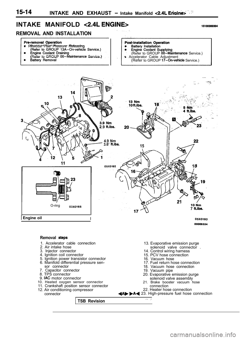
INTAKE AND EXHAUST Intake Manifold
INTAKE MANIFOLD
REMOVAL AND INSTALLATION
l Residual Fuel Pressure Releasing
(Refer to GROUP
Service.) (Refer to GROUP Service.)
l Accelerator Cable Adjustment
(Refer to GROUP
Service.)
2.9
4.9 Nm 3.6’ 15
O-ring
Engine oilI
18
10 Nm7
Removal
1. Accelerator cable connection2. Air intake hose3. Injector connector4. Ignition coil connector
5. Ignition power transistor connector
6. Manifold differential pressure sen-
sor connector
7. Capacitor connector
8. TPS connector
9. motor connector
10. Heated oxygen sensor connector
11. Crankshaft position sensor connector12. Air conditioning compressor
connector
13. Evaporative emission purge
solenoid valve connector .
14. Control wiring harness
15. PCV hose connection
16. Vacuum hose17. Fuel return hose connection18. Vacuum hose connection
19. Vacuum pipe
20. Evaporative emission purge solenoid valve assembly
21. Brake booster vacuum hose
connection22. Heater hose connection 23. High-pressure fuel hose connection
TSB Revision
Page 786 of 2103
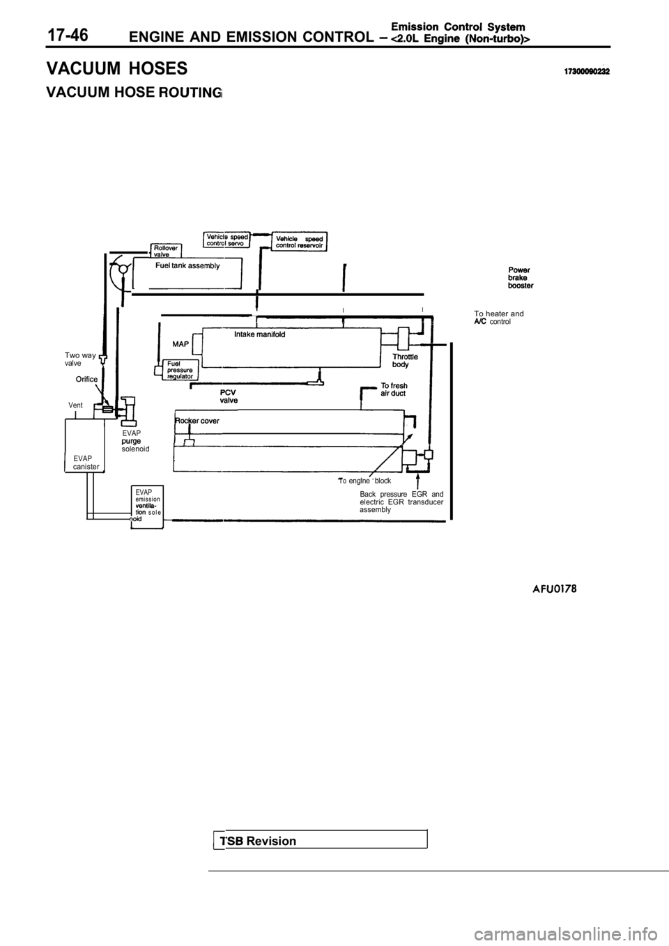
17-46ENGINE AND EMISSION CONTROL
VACUUM HOSES
VACUUM HOSE
Two wayvalve
II
To heater and
control
EVAPcanister
Vent
EVAP
solenoid
T oengine block
EVAPem i s s i o nBack pressure EGR andelectric EGR transducer s o l eassembly
Revision
Page 1927 of 2103
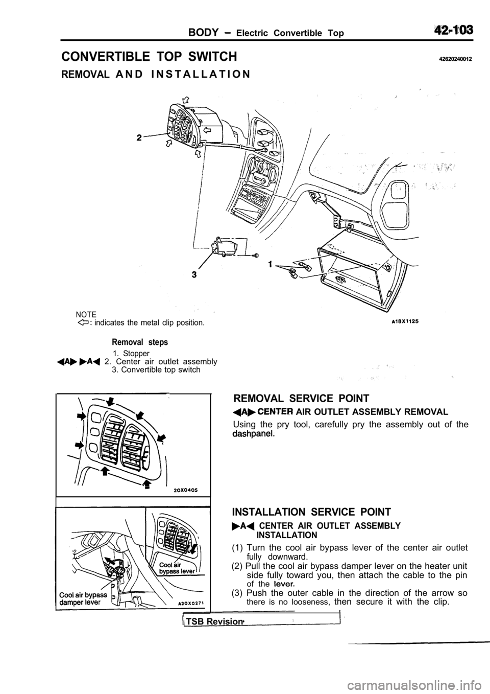
BODY Electric Convertible Top
CONVERTIBLE TOP SWITCH
REMOVAL
42620240012
A N D I N S T A L L A T I O N
NOTE indicates the metal clip position.
Removal steps
1. Stopper 2. Center air outlet assembly3. Convertible top switch
REMOVAL SERVICE POINT
AIR OUTLET ASSEMBLY REMOVAL
Using the pry tool, carefully pry the assembly out of the
INSTALLATION SERVICE POINT
CENTER AIR OUTLET ASSEMBLY
INSTALLATION
(1) Turn the cool air bypass lever of the center ai r outlet
fully downward.
(2) Pull the cool air bypass damper lever on the heater unit
side fully toward you, then attach the cable to the pin
of the
(3) Push the outer cable in the direction of the ar row so
there is no looseness, then secure it with the clip.
TSB Revision
Page 1961 of 2103
INTERIOR Instrument Panel
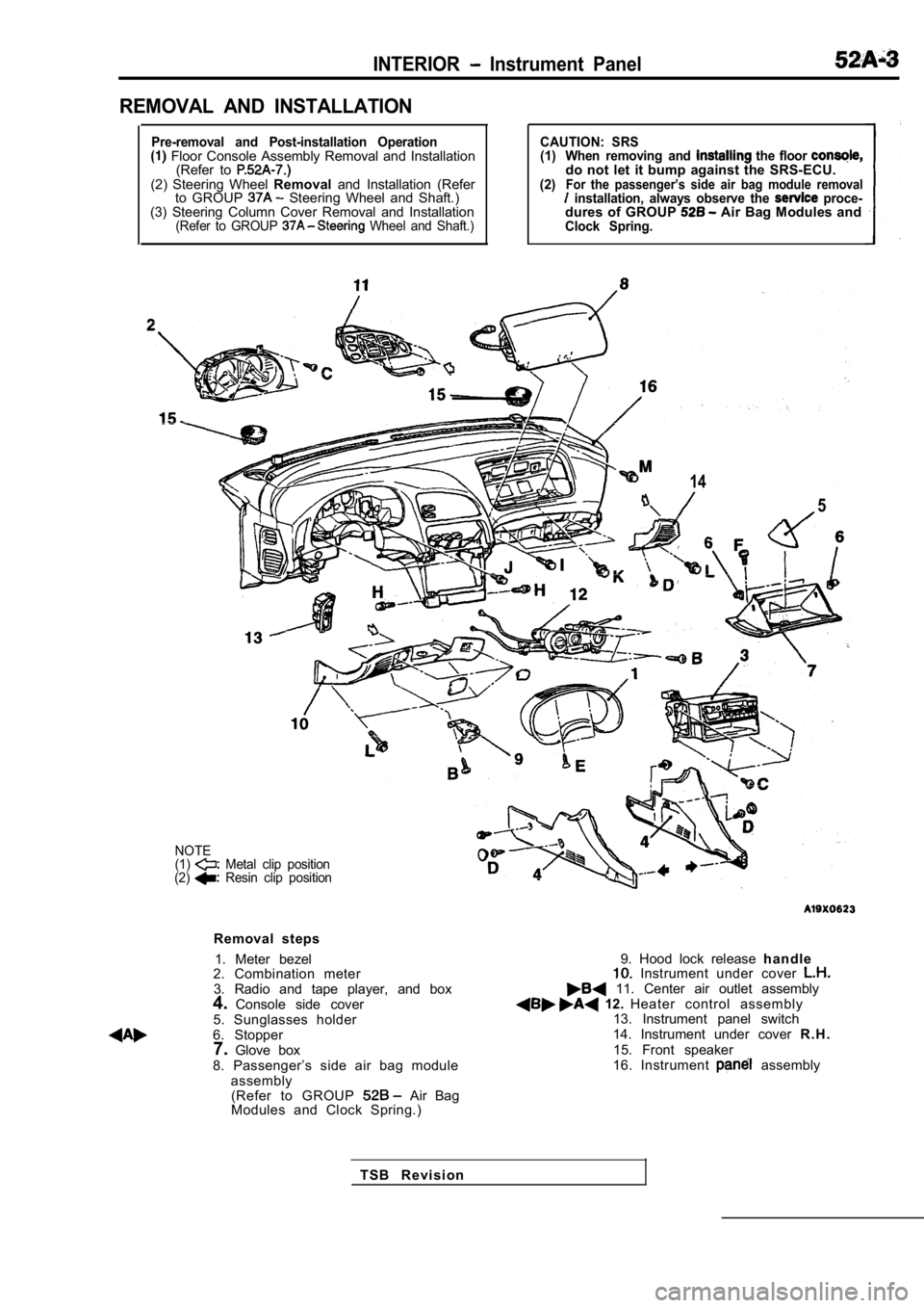
REMOVAL AND INSTALLATION
Pre-removal and Post-installation Operation Floor Console Assembly Removal and Installation(Refer to
(2) Steering Wheel Removaland Installation (Refer
to GROUP Steering Wheel and Shaft.)
(3) Steering Column Cover Removal and Installation
(Refer to GROUP Wheel and Shaft.)
CAUTION: SRS
(1) When removing and the floor do not let it bump against the SRS-ECU.(2)For the passenger’s side air bag module removal installation, always observe the proce-dures of GROUP Air Bag Modules andClock Spring.
14
5
NOTE
(1) Metal clip position
(2) Resin clip position
Removal steps
1. Meter bezel
2. Combination meter
3. Radio and tape player, and box
4. Console side cover
5. Sunglasses holder
6. Stopper 7. Glove box
8. Passenger’s side air bag module assembly(Refer to GROUP
Air Bag
Modules and Clock Spring.)
9. Hood lock release h a n d l e Instrument under cover 11. Center air outlet assembly 12. Heater control assembly
13. Instrument panel switch
14. Instrument under cover R . H .
15. Front speaker
16. Instrument
assembly
T S B R e v i s i o n
Page 1962 of 2103
INTERIOR Instrument Panel
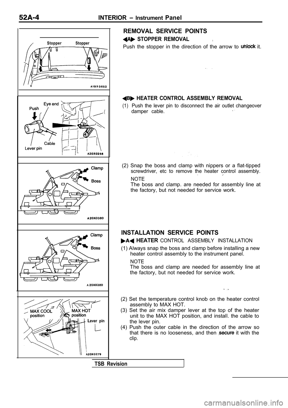
Stopper Stopper
II
A
Lever pin
REMOVAL SERVICE POINTS
STOPPER REMOVAL,
Push the stopper in the direction of the arrow to it.
HEATER CONTROL ASSEMBLY REMOVAL
(1)Push the lever pin to disconnect the air outlet changeover
damper cable..
(2) Snap the boss and clamp with nippers or a flat- tipped
screwdriver, etc to remove the heater control assem bly.
NOTE
The boss and clamp. are needed for assembly line at
the factory, but not needed for service work.
INSTALLATION SERVICE POINTS
HEATER CONTROL ASSEMBLY INSTALLATION
(1) Always snap the boss and clamp before installing a new
heater control assembly to the instrument panel.
NOTE
The boss and clamp are needed for assembly line at
the factory, but not needed for service work.
(2) Set the temperature control knob on the heater control
assembly to MAX HOT.
(3) Set the air mix damper lever at the top of the heater
unit to the MAX HOT position, and install. the cabl e to
the lever pin.
(4) Push the outer cable in the direction of the ar row so
that there is no looseness, and then
it with the
clip.
TSB Revision