key battery MITSUBISHI SPYDER 1990 Service User Guide
[x] Cancel search | Manufacturer: MITSUBISHI, Model Year: 1990, Model line: SPYDER, Model: MITSUBISHI SPYDER 1990Pages: 2103, PDF Size: 68.98 MB
Page 1867 of 2103

BODY
the passenger’s side door lock is turned with
NGDoor lock key cylinder SW(Refer to . .
NGCheck the following Repair.
and .
OK
Check trouble symptom.. .
NGN GMeasure at the key cylinder switch (passenger’s sid e) connector Check the harness between the side) and the door lock power .
Disconnect the connector and measure at harness sid e. between terminal (3) and groundOK:Battery positive voltage .
OK
Check the harness between the key cylinder switch (
passenger’s
side) and the ground. Repair, if necessary.
KEY REMINDER SYSTEM
INSPECTION CHART FOR TROUBLE SYMPTOMS
T r o u b l e s y m p t o m
Probable cause
If the driver’s side inside lock knob is lBroken wire in input circuit in door
locked under the following conditions, the switch.
Chart A
door can not be locked:l Door switch is faulty.
lThe key is inserted in the ignition key l
cylinder..
lThe driver’s side door is closed.
If the driver’s side inside lock knob ‘is lBroken wire in input circuit in Check
locked under the following conditions, the
switch.
door will be locked:l
Door switch is faulty.(Refer-to
lThe key is inserted in the ignition key l
cylinder.l
Broken wire in input in key
lThe driver’s side door is opened.reminder switch.l ETACS-ECU is faulty
If the driver’s side inside lock knob is
Check accordingto
locked under the following conditions, the reminder switch.
door can not be locked:lKey reminder. switch is faulty.(Refer to
lThe key is removed from the ignition l
key cylinder.lThe driver’s side door is opened.
TSB Revision
Page 1884 of 2103
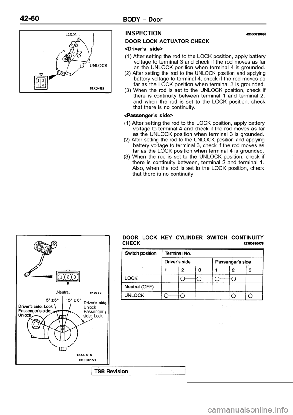
BODY Door
LOCK .INSPECTION
DOOR LOCK ACTUATOR CHECK
(1) After setting the rod to the LOCK position, apply battery
voltage to terminal 3 and check if the rod moves as far
as the UNLOCK position when terminal 4 is grounded.
(2) After setting the rod to the UNLOCK position an d applying
battery voltage to terminal 4, check if the rod moves as
far as the LOCK position when terminal 3 is grounde d.
(3) When the rod is set to the UNLOCK position, che ck if
there is continuity between terminal 1 and terminal 2,
and when the rod is set to the LOCK position, check
that there is no continuity.
side>
(1) After setting the rod to the LOCK position, app ly battery
voltage to terminal 4 and check if the rod moves as far
as the UNLOCK position when terminal 3 is grounded.
(2) After setting the rod to the UNLOCK position an d applying
battery voltage to terminal 3, check if the rod moves as
far as the LOCK position when terminal 4 is grounde d.
(3) When the rod is set to the UNLOCK position, che ck if
there is continuity between, terminal 2 and termina l 1.
Also, when the rod is set to the LOCK position, che ck
that there is no continuity.
Neutral
Driver’sUnlock Passenger’:
side: Lock
DOOR LOCK KEY CYLINDER SWITCH CONTINUITY
CHECK
Page 1900 of 2103
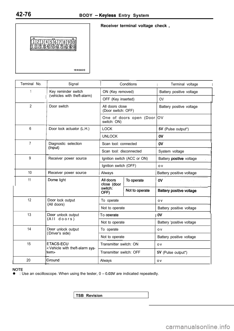
42-76B O D Y Entry System
Terminal No.
1
2
6
7
9
10
11
12
13
14
15
20
Receiver terminal voltage check ,
SignalConditionsITerminal voltageI
Key reminder switch
(vehicles with theft-alarm) ON (Key removed)
OFF (Key inserted) Battery positive voltage
OV
Door switch
Door lock actuator (L.H.) All doors close
(Door switch: OFF) Battery positive voltage
O n e o f d o o r s o p e n ( D o o r O V
switch: ON)
LOCK
(Pulse output*)
UNLOCK
Diagnostic selection
Receiver power source Scan tool: connected
Scan tool: disconnected Ignition switch (ACC or ON)
Ignition switch (OFF)
System voltage
Battery
voltage
o v
,
TSB Revision
Receiver power source Always Battery positive voltage
light
lock output
All doors)To operate
Not to operate
o v
Battery positive voltage
unlock output
A l l d o o r s ) To
Not to operate
II
Battery ‘positive voltage
unlock output
Driver’s side)To operate
Not to operate
o v
Battery positive voltage
Transmitter switch: ONo vVehicle with theft-alarm
Transmitter switch: OFF (Pulse output*)
Alwayso v
l : Use an oscilloscope. When using the tester, 0
are indicated repeatedly.
I
Page 2012 of 2103

SRS Troubleshooting
INSPECTION PROCEDURE FOR DIAGNOSTIC’
Code No. 14 Analog sensor system Probable cause,
[Comment]l
Malfunction of SRS-ECU
The SRS-ECU monitors the analog sensor output and outputs this code whenit detects a sensor failure, abnormal sensor charac teristics or abnormal sensor output.
Insulating tape
,Caution
Turn the ignition key to the “LOCK” position, disco nnect
the negative battery cable and tape the terminal.
Wait at least 60 seconds after disconnecting the battery
cable before doing any further work. (Refer to
Replace the SRS-ECU.
Code No. 15 or 16Safing sensor systemProbable
, l Malfunction of SRS-ECU
These codes are output when the resistance value be tween the safing
sensor
terminals in the SW-ECU is out of the normal range. Refer to the following table 1 for the trouble caus es of each code No.”
Table 1
Code No. Trouble Symptom
15Safing sensor short-circuited
16Safing sensor open-circuited. .
Insulating tapeICaution
Turn the ignition the position, disconnect
the negative battery cable and tape the terminal. Wait at least 60 seconds after disconnecting the ba ttery
cable before doing any further work. (Refer to P.
Replace the SRS-ECU.
TSBRevision
Page 2013 of 2103

SRS
Code No. or 62 Driver’s air bag module (squib) system
[Comment]These diagnostic trouble codes are output if there is abnormal resistance between the input terminals
of the driver’s air bag module (squib). Refer to the following table 1 for the trouble caus es of each code No.
Table 1
Probable cause
l Malfunction of l of harnesses orconnectorsl of bag
l of SRS-ECU
Code No. Trouble I
21
22
l Short in driver’s air bag module (squib) or harness short
l Short in clock spring
Open circuit in driver’s air bag module (squib) or open harness Open circuit in Malfunction of connector contact
61The harness wire of the driver’s air bag module (sq uib) is grounded to the power supply.
62The harness wire of the driver’s air bag module (sq uib) is grounded.
tape
Battery
cable
Caution
Turn the ignition key to the
position, disconnect
the negative battery cable and tape the
Wait at least 60 seconds after disconnecting the ba ttery
cable before doing any further work. (Refer to
check harnessSCAN TOOL DIAGNOSTIC
TROUBLE CODE
Disconnectclocksprlngconnector
Connect check harness
connector (1).
Erase diagnostic trouble codememory.
Are code Nos. or 62 output?
No
Clock spring check Repair
OK
Yes
the SRS-ECU and clock
Replace the SRS-ECU.
Replace the driver’s air bag module.
Revision I
Page 2014 of 2103

8SRS Troubleshooting
Code No. or 65 Front passenger’s air bag module (squib)
systemProbable cause
[Comment]l o f o r
These diagnostic trouble codes are output if there is abnormal resistance between the input terminals l
of the front passenger’s air bag module (squib).
Refer to the following table 1 for the trouble caus es of each code No. air bag module (squib)
l Malfunction of SRS-ECU
Table
Code No. Trouble Symptom
24
25
64Short in front passenger’s air bag module (squib) o r harness short
l Open circuit in front passenger’s air bag module (s quib) or open harness
l Malfunction of connector contact
The harness wire of the front passenger’s air bag m odule (squib) is grounded to the power supply.
65The harness wire of the front passenger’s air bag m odule (squib) is grounded.I
Insulating tape
0 Battery
cable
check harness
Caution
Turn the ignition key to the “LOCK” position, disco nnect
the negative battery cable and tape the terminal.
Wait at least 60 seconds after disconnecting the ba ttery
cable before doing any further work. (Refer to P.
SCANTOOL DIAGNOSTIC
TROUBLE CODE
l Disconnect front passenger’s air
bag module connector
l Connect SRS check harness
connector (1).
l Erase diagnostic trouble code
memory.
Are code Nos. or 65 output?
Yes
TSB Revision
Replace the front passenger’s air bag module.
Check
Replace the SRS-ECU.
Page 2015 of 2103

SRS Troubleshooting
Code No. 31 or 32 SRS-ECU capacitor systemProbable cause
[Comment]l Malfunction of These diagnostic trouble codes are output if the vo ltage at the SRS-ECU capacitor
terminals is higher (No. 31) or lower (No. 32) than the value for 5 seconds
or more.
However, if diagnostic trouble code Nos. 41 and 42 are being output due to a drop
in battery voltage, code No. 32 will not be detecte d.
Insulating tape
Caution
Turn the ignition key to the “LOCK” position, disco nnect
the negative battery cable and tape the terminal.
Wait at least 60 seconds after disconnecting the ba ttery
cable before doing any further work. (Refer to
Battery cable
Replace the SRS-ECU.
Code No. 34 Connector lock system Probable cause
[Comment]l Malfunction of connectors
This diagnostic trouble code is output when the SRS -ECU connector is connectedl
Malfunction of SRS-ECU
improperly.However, if the vehicle condition returns to normal , diagnostic trouble code No. 34
will be automatically erased, and the SRS light will switch off.
insulating tape
Battery cable
Caution
Turn the ignition key to the “LOCK” position, disco nnect
the negative battery cable and tape the terminal.
Wait at least 60 seconds after disconnecting the ba ttery
cable before doing any further work. (Refer to P.
Check trouble symptom.
OKNG
Repair
Replace the SRS-ECU.
TSB Revision
Page 2016 of 2103

SRS Troubleshooting
Code No. 35 SRS-ECU (after deployment of the air bag)
systemP r o b a b l e
[Comment]l M a l f u n c t i o n o f S R S - E C U After deployment of the air bag, this code is outpu t.
If this code is output before
deployment of the air bag, a trouble in the SRS-ECU is suspected.
Insulating tape
Battery cable
Caution
Turn the ignition key to the “LOCK”
the negative battery cable and tape the
Wait at least 60 after disconnecting the battery
cable before doing any further
(Refer
Replace the SRS-ECU.
TSB Revision
Page 2017 of 2103

Troubleshooting
Code No. 41 (A) power circuit systemP r o b a b l e
[Comment]l Malfunction of harnesses or connectors
This diagnostic trouble code is output if the volta ge between the (A) terminall
Malfunction of SRS-ECU,
and the ground is lower than the specified value fo r a continuous period of 5 secondsor more.
However, if the vehicle condition returns to normal , diagnostic trouble code No. 41
will be automatically erased, and the
light will switch off., .
Insulating tape
cable
I
Caution
Turn the ignition key to the “LOCK” position,
. the negative battery cable and tape terminal.
Wait at least 60 seconds after
battery
cable before doing any further work. (Refer P.
SRS check harness
OK
Measure at check harnessconnector (5).l Disconnect SRS-ECU connector
l Connect SRS check harness
connector (3).
lContinuity between terminals (20)
OK: Continuity
C h e c k t h efollowing
Check trouble symptom. .
N G
l Disconnect SRS-ECU connector l Connect check harness connector (3)
l Ignition switch: ON
l Voltage between terminal (14) and ground
OK: 9
or more
OK
Replace the SRS-ECU.
TSB Revision
Page 2018 of 2103

SRS Troubleshooting
Code No. 42 (B) power circuit system Probable cause
[Comment]l Malfunction of harnesses or connectorsThis diagnostic trouble code is output if the voltage between the terminaland the ground is lower than the specified value fo r a continuous period of secondsor more.
However, if the vehicle condition returns to normal , diagnostic trouble code NO. 42
will be automatically erased, and the SRS warning l ight will switch off.
Battery
cableI
SRS check harness
Caution
Turn the ignition key to the “LOCK” position, disco nnect
the negative battery cable and tape the terminal.
Wait at least 60 seconds after disconnecting the battery
cable before doing any further work. (Refer to P.
Measure at SRS check harness
connector (5). l Disconnect SRS-ECU connector
l Connect SRS check harness
connector (3).
lContinuity between (20)
OK: Continuity
0 0 0 0 3 9 2 4
OK
Measure at SRS check harness connector (5).
l Disconnect SRS-ECU connector
l Connect SRS check harness connector (3)
l Ignition switch: ON
l Voltage between terminal (13) and ground
OK:
or more
O K
I
the
OK
Check trouble symptom.
NG
NG C h e c k t h eNGfollowingconnectors: and
OK
ICheck trouble symptom.
NG
Repair
TSB Revision