fuel cap MITSUBISHI SPYDER 1990 Service Repair Manual
[x] Cancel search | Manufacturer: MITSUBISHI, Model Year: 1990, Model line: SPYDER, Model: MITSUBISHI SPYDER 1990Pages: 2103, PDF Size: 68.98 MB
Page 3 of 2103
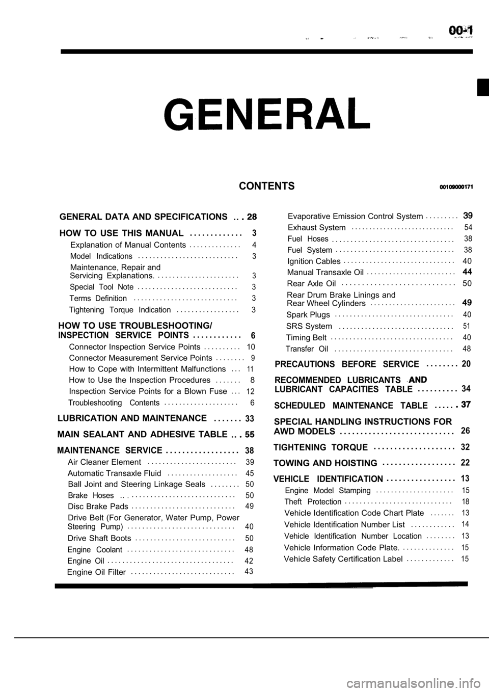
CONTENTS
GENERAL DATA AND SPECIFICATIONS. .
HOW TO USE THIS MANUAL. . . . . . . . . . . . .3
Explanation of Manual Contents. . . . . . . . . . . . . .4
Model Indications
. . . . . . . . . . . . . . . . . . . . . . . . . . .3
Maintenance, Repair and
Servicing Explanations. . . . . . . . . . . . . . . . . . . . . . .
3
Special Tool Note. . . . . . . . . . . . . . . . . . . . . . . . . . .3
Terms Definition. . . . . . . . . . . . . . . . . . . . . . . . . . . .3
Tightening Torque Indication. . . . . . . . . . . . . . . . .3
HOW TO USE TROUBLESHOOTING/
INSPECTION SERVICE POINTS. . . . . . . . . . . .6
Connector Inspection Service Points
. . . . . . . . . .10
Connector Measurement Service Points . . . . . . . .9
How to Cope with Intermittent Malfunctions . . .11
How to Use the Inspection Procedures
. . . . . . .
8
Inspection Service Points for a Blown Fuse . . .
12
Troubleshooting Contents. . . . . . . . . . . . . . . . . . . .6
LUBRICATION AND MAINTENANCE . . . . . . .33
MAIN SEALANT AND ADHESIVE TABLE
. .
MAINTENANCE SERVICE. . . . . . . . . . . . . . . . . .38
Air Cleaner Element. . . . . . . . . . . . . . . . . . . . . . . .39
Automatic Transaxle Fluid
. . . . . . . . . . . . . . . . . . .45
Ball Joint and Steering Linkage Seals
. . . . . . . .50
Brake Hoses.... . . . . . . . . . . . . . . . . . . . . . . . . . . .50
Disc Brake Pads. . . . . . . . . . . . . . . . . . . . . . . . . . . .49
Drive Belt (For Generator, Water Pump, Power
Steering Pump). . . . . . . . . . . . . . . . . . . . . . . . . . . . .40
Drive Shaft Boots
. . . . . . . . . . . . . . . . . . . . . . . . . . .50
Engine Coolant. . . . . . . . . . . . . . . . . . . . . . . . . . . . .48
Engine Oil. . . . . . . . . . . . . . . . . . . . . . . . . . . . . . . . . .42
Engine Oil Filter. . . . . . . . . . . . . . . . . . . . . . . . . . . .43
Evaporative Emission Control System . . . . . . . . .
Exhaust System. . . . . . . . . . . . . . . . . . . . . . . . . . . . .54
Fuel Hoses. . . . . . . . . . . . . . . . . . . . . . . . . . . . . . . . .38
Fuel System. . . . . . . . . . . . . . . . . . . . . . . . . . . . . . . .38
Ignition Cables. . . . . . . . . . . . . . . . . . . . . . . . . . . . . .
40
Manual Transaxle Oil . . . . . . . . . . . . . . . . . . . . . . . .
Rear Axle Oil. . . . . . . . . . . . . . . . . . . . . . . . . . . .
50
Rear Drum Brake Linings and
Rear Wheel Cylinders . . . . . . . . . . . . . . . . . . . . . . .
Spark Plugs. . . . . . . . . . . . . . . . . . . . . . . . . . . . . . . .40
SRS System . . . . . . . . . . . . . . . . . . . . . . . . . . . . . . .51
Timing Belt. . . . . . . . . . . . . . . . . . . . . . . . . . . . . . . . .40
Transfer Oil. . . . . . . . . . . . . . . . . . . . . . . . . . . . . . . .48
PRECAUTIONS BEFORE SERVICE. . . . . . . .20
RECOMMENDED LUBRICANTS
LUBRICANT CAPACITIES TABLE. . . . . . . . . .34
SCHEDULED MAINTENANCE TABLE. . . . .
SPECIAL HANDLING INSTRUCTIONS FOR
AWD MODELS . . . . . . . . . . . . . . . . . . . . . . . . . . . .
26
TIGHTENING TORQUE. . . . . . . . . . . . . . . . . . . .32
TOWING AND HOISTING . . . . . . . . . . . . . . . . . .22
VEHICLE IDENTIFICATION. . . . . . . . . . . . . . . . .13
Engine Model Stamping. . . . . . . . . . . . . . . . . . . . .15
Theft Protection. . . . . . . . . . . . . . . . . . . . . . . . . . . . .18
Vehicle Identification Code Chart Plate
. . . . . . .13
Vehicle Identification Number List. . . . . . . . . . . .14
Vehicle Identification Number Location. . . . . . . .13
Vehicle Information Code Plate.. . . . . . . . . . . . . .15
Vehicle Safety Certification Label
. . . . . . . . . . . . .15
Page 30 of 2103
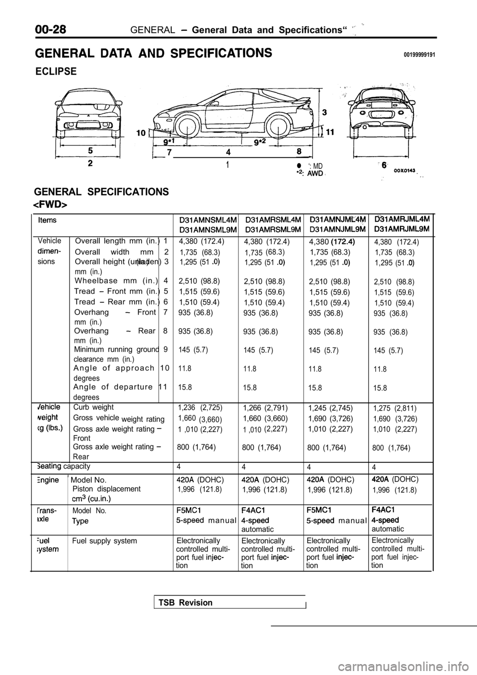
GENERAL General Data and Specifications“
00199999191
ECLIPSE
74
1l ‘: MD
.
GENERAL SPECIFICATIONS
VehicleOverall length mm (in.) 14,380 (172.4)4,380 (172.4)4,3804,380 (172.4)
Overall width mm 21,735 (68.3) 1,735
sions(in.) (68.3)
1,735 (68.3)1,735 (68.3)
Overall height (unladen) 31,295 (51 1,295 (51 1,295 (51 1,295(51
mm (in.)
W h e e l b a s e m m ( i n . ) 42,510 (98.8)
2,510 (98.8)2,510 (98.8)2,510 (98.8)
Tread Front mm (in.) 51,515 (59.6)
1,515 (59.6) 1,515 (59.6)1,515 (59.6)
Tread Rear mm (in.) 61,510 (59.4)
1,510 (59.4) 1,510 (59.4)1,510 (59.4)
Overhang Front 7935 (36.8)
935 (36.8) 935 (36.8)935 (36.8)
mm (in.)
Overhang Rear 8935 (36.8) 935 (36.8) 935 (36.8)935 (36.8)
mm (in.)
Minimum running ground 9145 (5.7) 145 (5.7) 145 (5.7)145 (5.7)
clearance mm (in.)
A n g l e o f a p p r o a c h 1 011.8 11.8 11.811.8
degrees
A n g l e o f d e p a r t u r e 1 115.8
15.8 15.815.8
degrees
Curb weight1,236 (2,725)1,266 (2,791) 1,245 (2,745)1,275 (2,811)
Gross vehicle
weight rating1,660(3,660)1,660 (3,660) 1,690 (3,726)1,690 (3,726)
Gross axle weight rating1 ,010 (2,227)1 ,010(2,227)1,010 (2,227)1,010 (2,227)
Front
Gross axle weight rating
800 (1,764) 800 (1,764) 800 (1,764)800 (1,764)
Rear
capacity4 4 44
Model No. (DOHC) (DOHC) (DOHC) (DOHC)
Piston displacement
1,996 (121.8)1,996 (121.8) 1,996 (121.8)1,996 (121.8)
Model No.
m a n u a l m a n u a l
automatic automatic
Fuel supply system
Electronically
Electronically ElectronicallyElectronically
controlled multi- controlled multi- controlled multi-controlled multi-
port fuel port fuel port fuel port fuel injec-
tion
tion tiontion
TSB RevisionI
Page 31 of 2103
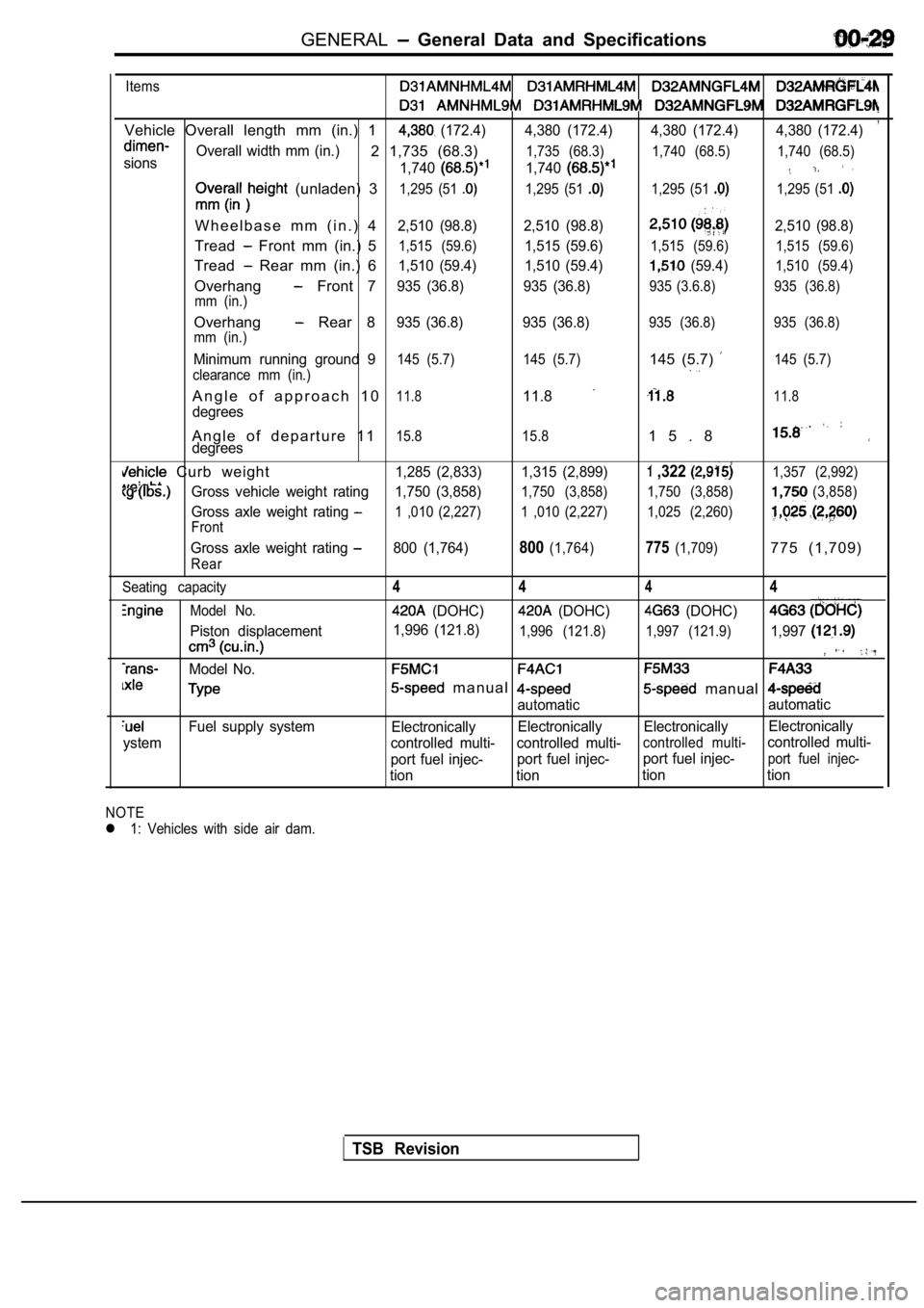
GENERAL General Data and Specifications
Items
,Vehicle Overall length mm (in.) 1 (172.4) 4,380 (172.4) 4,380 (172.4) 4,380 (172.4)
sionsOverall width mm (in.)2 1,735 (68.3)
1,740
1,735 (68.3)
1,740
1,740 (68.5) 1,740 (68.5)
(unladen) 31,295 (51 1,295 (51 1,295 (51 1,295 (51
W h e e l b a s e m m ( i n . ) 42,510 (98.8) 2,510 (98.8)2,510 (98.8)
Tread Front mm (in.) 51,515 (59.6)1,515 (59.6)1,515 (59.6) 1,515 (59.6)
Tread Rear mm (in.) 61,510 (59.4) 1,510 (59.4) (59.4)1,510 (59.4)
Overhang Front 7935 (36.8) 935 (36.8)935 (3.6.8) 935 (36.8)
mm (in.)
Overhang Rear 8935 (36.8) 935 (36.8)935 (36.8) 935 (36.8)
mm (in.)
Minimum running ground 9145 (5.7) 145 (5.7)145 (5.7) 145 (5.7)
clearance mm (in.)
A n g l e o f a p p r o a c h 1 011.811.811.8
degrees
A n g l e o f d e p a r t u r e 1 115.8 15.81 5 . 8degrees
Curb weight1,285 (2,833) 1,315 (2,899) ,322 1,357 (2,992)
Gross vehicle weight rating 1,750 (3,858)1,750 (3,858) 1,750 (3,858)(3,858)
Gross axle weight rating 1 ,010 (2,227) 1 ,010 (2,227) 1,025 (2,260)
Front
Gross axle weight rating 800 (1,764)800(1,764)775(1,709)775 (1,709)
Rear
Seating capacity
Model No.
Piston displacement
Model No.
Fuel supply system
ystem
4 444
(DOHC) (DOHC) (DOHC)
1,996 (121.8)1,996 (121.8) 1,997 (121.9)1,997
m a n u a l manual
automatic automatic
Electronically Electronically Electronically Electronically
controlled multi- controlled multi-
controlled multi-controlled multi-
port fuel injec- port fuel injec-port fuel injec-
port fuel injec-
tion tion tion tion
NOTE
l 1: Vehicles with side air dam.
TSB Revision
Page 32 of 2103
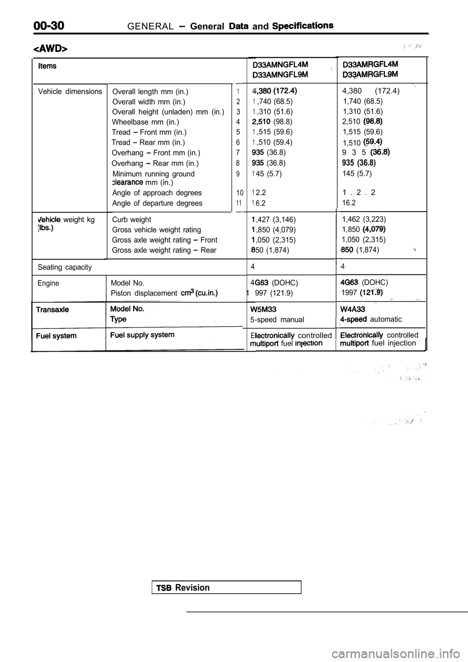
GENERAL General and
Vehicle dimensions
weight kg
Overall length mm (in.)
Overall width mm (in.)
Overall height (unladen) mm (in.)
Wheelbase mm (in.)
Tread
Front mm (in.)
Tread
Rear mm (in.)
Overhang
Front mm (in.)
Overhang
Rear mm (in.)
Minimum running ground
mm (in.)
Angle of approach degrees
Angle of departure degrees
Curb weight
Gross vehicle weight rating
Gross axle weight rating
Front
Gross axle weight rating
Rear
1
2
3
4 5
6
7
8
9
10
11
Seating capacity
EngineModel No.
Piston displacement
4
1,740 (68.5)
1,310 (51.6)
(98.8)
1,515 (59.6)
1,510 (59.4)
(36.8)
(36.8)
145 (5.7)
4,380 (172.4)
1,740 (68.5)
1,310 (51.6)
2,510
1,515 (59.6)
1,510
9 3 5
935 (36.8)
145 (5.7)
12.2
16.2
,427 (3,146)
,850 (4,079)
,050 (2,315)
50 (1,874)
4
4
1
5
El
1 . 2 . 2
16.2
1,462 (3,223)
1,850
1,050 (2,315)
(1,874)
4
(DOHC)
997 (121.9)
-speed manual
(DOHC)
1997
automatic
controlled controlled
fuel fuel injection
Revision
Page 33 of 2103
GENERAL General Data and Specifications
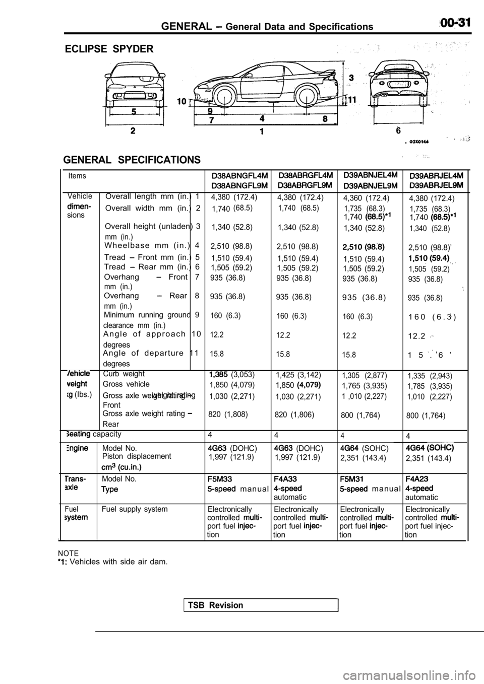
ECLIPSE SPYDER
GENERAL SPECIFICATIONS
6
.
Items
VehicleOverall length mm (in.) 14,380 (172.4) 4,380 (172.4)
4,360 (172.4)4,380 (172.4)
Overall width mm (in.) 21,740(68.5)
1,740 (68.5)
1,735 (68.3)1,7401,735 (68.3)sions
1,740
Overall height (unladen) 31,340 (52.8)1,340 (52.8)
1,340 (52.8)1,340 (52.8)
mm (in.)
W h e e l b a s e m m ( i n . ) 42,510 (98.8) 2,510 (98.8)2,510 (98.8)’
Tread Front mm (in.) 51,510 (59.4) 1,510 (59.4)
1,510 (59.4)
Tread Rear mm (in.) 61,505 (59.2) 1,505 (59.2)
1,505 (59.2)1,505 (59.2)Overhang Front 7935 (36.8) 935 (36.8)
935 (36.8)935 (36.8)
mm (in.)
Overhang Rear 8935 (36.8) 935 (36.8)9 3 5 ( 3 6 . 8 )935 (36.8)
mm (in.)
Minimum running ground 9160 (6.3) 160 (6.3)
160 (6.3)1 6 0 ( 6 . 3 )
clearance mm (in.)
A n g l e o f a p p r o a c h 1 012.2 12.2
12.21 2 . 2
degrees
A n g l e o f d e p a r t u r e 1 115.8 15.8
15.81 5 . 6 ’
degrees
Curb weight (3,053)1,425 (3,142)1,305 (2,877) 1,335 (2,943)
Gross vehicle
1,765 (3,935)1,785 (3,935)
(Ibs.)weight rating1,850 (4,079)
1,850Gross axle weight rating 1,030 (2,271)1,030 (2,271)1 ,010 (2,227) 1,010 (2,227)
Front
Gross axle weight rating
820 (1,808) 820 (1,806)
800 (1,764)800 (1,764)
Rear
capacity
Model No.
Piston displacement
Model No.
FuelFuel supply system
NOTE
Vehicles with side air dam. 4
444
(DOHC) (DOHC) (SOHC)
1,997 (121.9)
1,997 (121.9)
2,351 (143.4)2,351 (143.4)
m a n u a l m a n u a l
automatic automatic
Electronically Electronically Electronically Electronically
controlled
controlledcontrolledcontrolled
port fuel port fuel port fuel port fuel injec-
tion tion tion tion
TSB Revision
Page 36 of 2103
Lubrication and
GENERAL Lubricants and Lubricant Capacities Table
Use of fuels containing alcohol is not recommended
unless the nature of the blend can be determined
as being satisfactory.
Gasohol
A mixture of 10% ethanol (grain alcohol)
and 90% unleaded gasoline may be used in your
car.
If problems are experienced as a result
of using gasohol, it is recommended that the car
be operated on gasoline.
Methanol Do not use gasolines containing
methanol (wood alcohol). Use of this type of alcohol
can result in vehicle performance deterioration and
damage critical parts in the fuel system compo-
nents. Fuel system damage and performance prob-
lems, resulting from the use of gasolines containin g
methanol, may not be covered by the new car war-
ranty.
Gasolines containing
Ether)
Unleaded gasoline containing 15% or
may be used in car. Fuel containing MTBE
over 15% vol. may cause reduced engine perfor-
mance and produce vapor lock or hard starting.
MATERIALS
TO FUEL
Indiscriminate use of fuel system -cleaning’
should be avoided. Many of these materials in-
tended for gum and varnish removal
highly active solvents or similar ingredients that
can be harmful to gasket and diaphragm materials
used in fuel system component
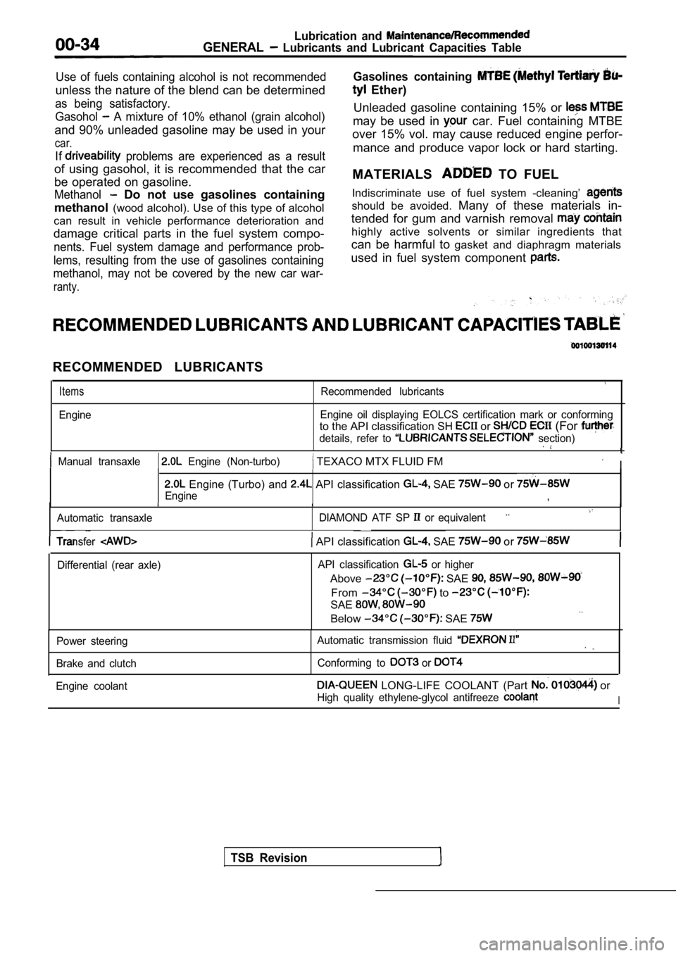
RECOMMENDED LUBRICANTS
Items
Engine
Recommended lubricants
Engine oil displaying EOLCS certification mark or c onforming
to the API classification SH or (For
details, refer to section)
Manual transaxle Engine (Non-turbo) TEXACO MTX FLUID FM I
Engine (Turbo) and API classification SAE or
Engine,
Automatic transaxle DIAMOND ATF SP or equivalent
TSB Revision
Transfer API classification SAE or
Differential (rear axle)API classification or higher
Above SAE
From to
SAE
Below SAE
Power steering
Brake and clutch Automatic transmission fluid
Conforming to or
Engine coolant LONG-LIFE COOLANT (Part or
High quality ethylene-glycol antifreeze I
Page 37 of 2103
GENERAL Recommended Lubricants and Lubricant Table
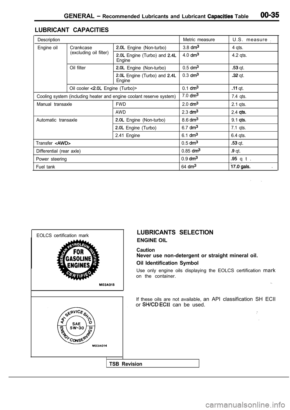
LUBRICANT CAPACITIES
DescriptionMetric measureU . S . m e a s u r e
Engine oil Crankcase Engine (Non-turbo)3.8
(excluding oil filter) 4 qts. Engine (Turbo) and 4.0
Engine4.2 qts.
Oil filter
Engine (Non-turbo) 0.5 qt.
Engine (Turbo) and 0.3
Engine
qt.
Oil cooler
Engine (Turbo)> 0.1 qt.
Cooling system (including heater and engine coolant reserve system)7.07.4 qts.
Manual transaxleFWD2.02.1 qts.
AWD2.32.4
Automatic transaxle Engine (Non-turbo)8.69.1
Engine (Turbo)
6.77.1 qts.
2.41 Engine 6.16.4 qts.
Transfer
0.5 qt.
Differential (rear axle) 0.85
qt.
Power steering
0.9 q t .
Fuel tank 64
EOLCS certification markLUBRICANTS SELECTION
ENGINE OIL
Caution
Never use non-detergent or straight mineral oil.
Oil Identification Symbol
Use only engine oils displaying the EOLCS certifica tion mark
on the container.
If these oils are not available, an API classification SH ECII
or
can be used.
TSB Revision
Page 41 of 2103
GENERAL Maintenance Service
Engine (Non-turbo)>
Engine (Turbo)>
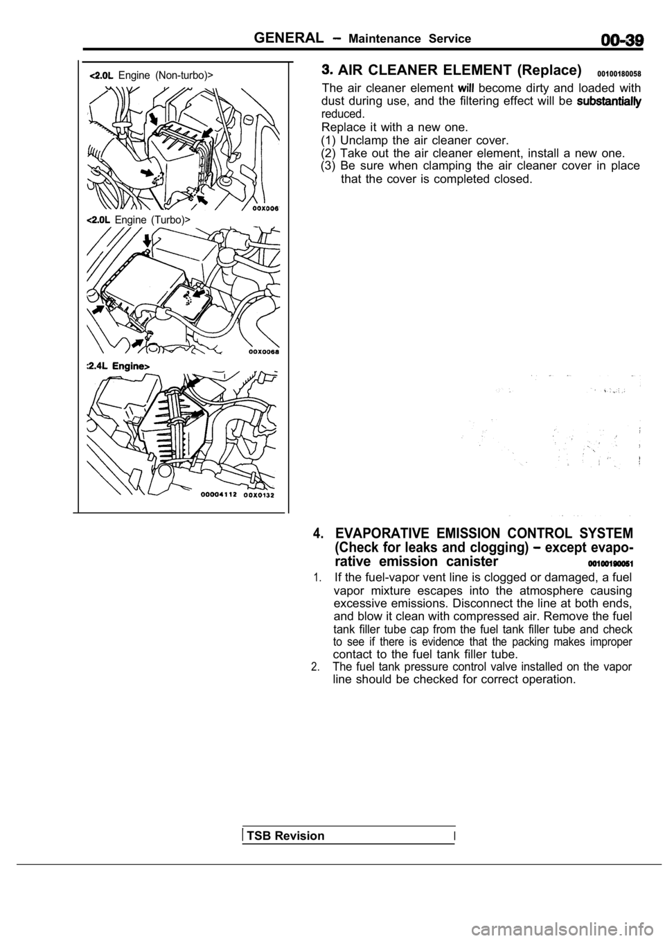
AIR CLEANER ELEMENT (Replace)00100180058
The air cleaner element become dirty and loaded with
dust during use, and the filtering effect will be
reduced.
Replace it with a new one.
(1) Unclamp the air cleaner cover.
(2) Take out the air cleaner element, install a new one.
(3) Be sure when clamping the air cleaner cover in place
that the cover is completed closed.
4.EVAPORATIVE EMISSION CONTROL SYSTEM
(Check for leaks and clogging)
except evapo-
rative emission canister
1.If the fuel-vapor vent line is clogged or damaged, a fuel
vapor mixture escapes into the atmosphere causing
excessive emissions. Disconnect the line at both en ds,
and blow it clean with compressed air. Remove the f uel
tank filler tube cap from the fuel tank filler tube and check
to see if there is evidence that the packing makes improper
contact to the fuel tank filler tube.
2.The fuel tank pressure control valve installed on the vapor
line should be checked for correct operation.
TSB RevisionI
Page 77 of 2103
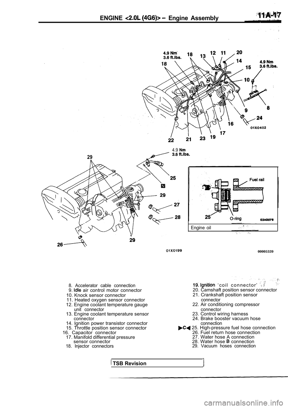
ENGINE Engine Assembly
4.9
29
8. Accelerator cable connection9. air control motor connector
10. Knock sensor connector 11. Heated oxygen sensor connector
12. Engine coolant temperature gauge
unit connector13. Engine coolant temperature sensorconnector
Engine oil
00005320
‘ c o i l c o n n e c t o r ’ 20. Camshaft position sensor connector
21. Crankshaft position sensor
connector22. Air conditioning compressor
connector23. Control wiring harness 24. Brake booster vacuum hose .
14. Ignition power transistor connector
15. Throttle position sensor connector
16. Capacitor connector 17. Manifold differential pressure sensor connector
18. Injector connectors connection
25. High-pressure fuel hose connection
26. Fuel return hose connection
27. Water hose A connection
28. Water hose
connection29. Vacuum hoses connection
TSB Revision
Page 91 of 2103
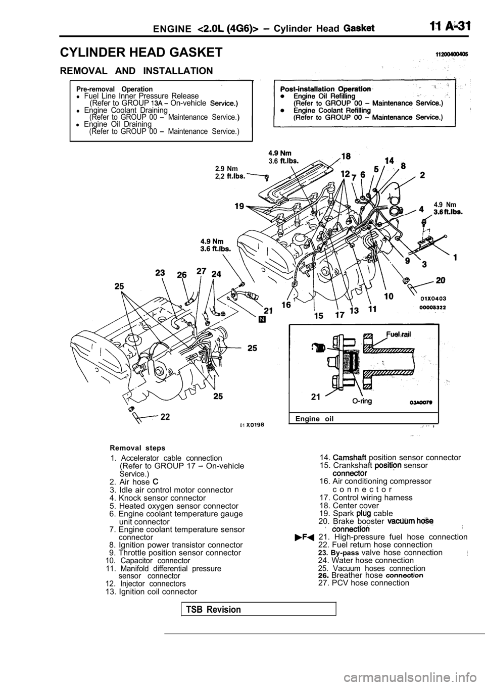
ENGINE Cylinder Head
CYLINDER HEAD GASKET
REMOVAL AND INSTALLATION
Pre-removal Operationl Fuel Line Inner Pressure Release(Refer to GROUP On-vehiclel Engine Coolant Draining(Refer to GROUP 00 Maintenance Service.)l Engine Oil Draining(Refer to GROUP 00 Maintenance Service.)
3.62.9 Nm
2.2
4.9 Nm
220 1
Removal steps
1. Accelerator cable connection(Refer to GROUP 17 On-vehicleService.)2. Air hose 3. Idle air control motor connector
4. Knock sensor connector
5. Heated oxygen sensor connector
6. Engine coolant temperature gauge
unit connector
7. Engine coolant temperature sensor
connector8. Ignition power transistor connector
9. Throttle position sensor connector
10. Capacitor connector
11. Manifold differential pressure sensor connector
12. Injector connectors
13. Ignition coil connector Engine oil
,
21
14. position sensor connector
15. Crankshaft sensor
16. Air conditioning compressor
c o n n e c t o r
17. Control wiring harness
18. Center cover
19. Spark
cable
20. Brake booster
21. High-pressure fuel hose connection 22. Fuel return hose connection
23. By-pass valve hose connection
24. Water hose connection25. Vacuum hoses connection26.Breather hose 27. PCV hose connection
TSB Revision