sensor MITSUBISHI SPYDER 1990 Service Owner's Manual
[x] Cancel search | Manufacturer: MITSUBISHI, Model Year: 1990, Model line: SPYDER, Model: MITSUBISHI SPYDER 1990Pages: 2103, PDF Size: 68.98 MB
Page 133 of 2103
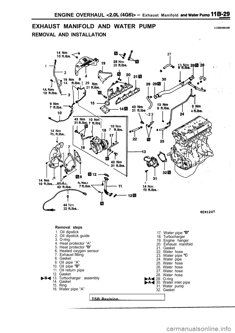
ENGINE OVERHAUL Exhaust Manifold
EXHAUST MANIFOLD AND WATER PUMP
REMOVAL AND INSTALLATION
11300490108
. .
10
Nm
120
2I
27
14 29
21
14 Nmin
Nm
I 7
I - Nm
13 Nm
‘ - 2 3
Nm
10
Nm32
Removal steps
1.Oil dipstick17.Water pipe 2.Oil dipstick guide18.Turbocharger3.O-ring19.Engine hanger4.Heat protector “A”20.Exhaust manifold5.Heat protector 21.Gasket6.Heated oxygen sensor22.Water hose7.Exhaust fitting23.Water pipe 8.Gasket24.Water pipe9.Oil pipe “A”25. Water hose10.Oil pipe 26.Water hose11.Oil return pipe27. Water hose12.Gasket28.Water hose13.Turbocharger assembly29. O-ring14.Gasket30.Water inlet pipe15.Ring31.Water pump16.Water pipe “A”32.Gasket
TSB Revision
Page 136 of 2103
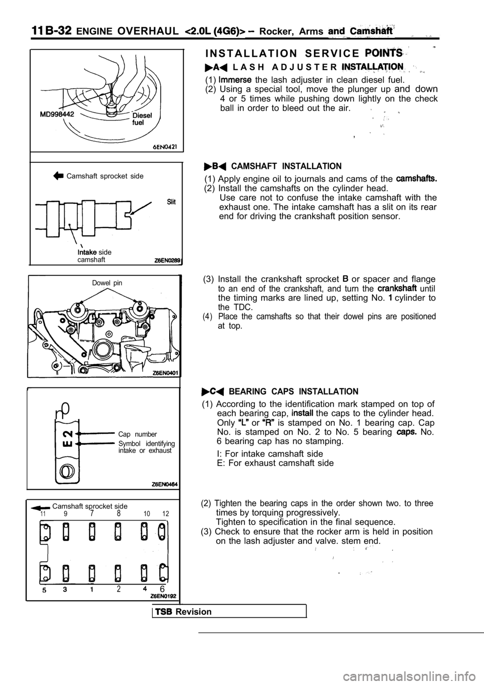
ENGINE OVERHAUL Rocker, Arms
Camshaft sprocket side
sidecamshaft
Dowel pin
n0
Cap number
Symbol identifying
intake or exhaust
0
Camshaft sprocket side1197 810 12
2 6
I N S T A L L A T I O N S E R V I C E
L A S H A D J U S T E R
(1) the lash adjuster in clean diesel fuel.
(2) Using a special tool, move the plunger up and down
4 or 5 times while pushing down lightly on the chec k
ball in order to bleed out the air.
,
CAMSHAFT INSTALLATION
(1) Apply engine oil to journals and cams of the
(2) Install the camshafts on the cylinder head. Use care not to confuse the intake camshaft with th e
exhaust one. The intake camshaft has a slit on its rear
end for driving the crankshaft position sensor.
(3) Install the crankshaft sprocket
or spacer and flange
to an end of the crankshaft, and turn the until
the timing marks are lined up, setting No. cylinder to
the TDC.
(4)Place the camshafts so that their dowel pins are po sitioned
at top.
BEARING CAPS INSTALLATION
(1) According to the identification mark stamped on top of
each bearing cap,
the caps to the cylinder head.
Only
or is stamped on No. 1 bearing cap. Cap
No. is stamped on No. 2 to No. 5 bearing
No.
6 bearing cap has no stamping.
I: For intake camshaft side
E: For exhaust camshaft side
(2) Tighten the bearing caps in the order shown two . to three
times by torquing progressively.
Tighten to specification in the final sequence.
(3) Check to ensure that the rocker arm is held in position
on the lash adjuster and valve. stem end.
.
Revision
Page 181 of 2103
ENGINE On-vehicle Service
IDLE MIXTURE CHECK
11100210081
1.Before inspection, set vehicles in the following co ndition:
lEngine coolant temperature:
l Lights, electric cooling fan and all accessories: O FF
lTransaxle: Neutral (P range on vehicles with
2.After turning the ignition switch to OFF, connect t he scan
tool to the data link connector.
3.Start the engine and run it at 2,500 for 2 minutes.
4. Set the CO, HC tester.
5. Check the CO contents and the HC contents at idl e.
Standard value:
CO contents: 0.5% or less
HC contents: 100 ppm or less
6. If the idle speed is outside the standard value, check
the following items: l Diagnostic output
l Closed-loop control (When the closed-loop control
is carried out normally, the output signal of the h eated
oxygen sensor repeats between and
,000 at idle.)
l Fuel pressure
I n j e c t o r
lIgnition coil, spark plug cable, spark plug
lEGR system and the EGR valve leak
l Evaporative emission control system
Compression pressure
NOTE
Replace the three-way catalyst whenever the CO and
HC contents do not remain inside the standard value .
(even though the result of the inspection is normal on
all items.)
COMPRESSION PRESSURE CHECK
1.Before inspection, check that the engine oil, start er and
battery are normal. Also, set the vehicle to the fo llowing
condition:
lEngine coolant temperature:
lLights, electric cooling fan and all accessories: O FF
lTransaxle: Neutral (P range on vehicle with
2. Disconnect the spark plug cables.
3. Remove all spark plugs.
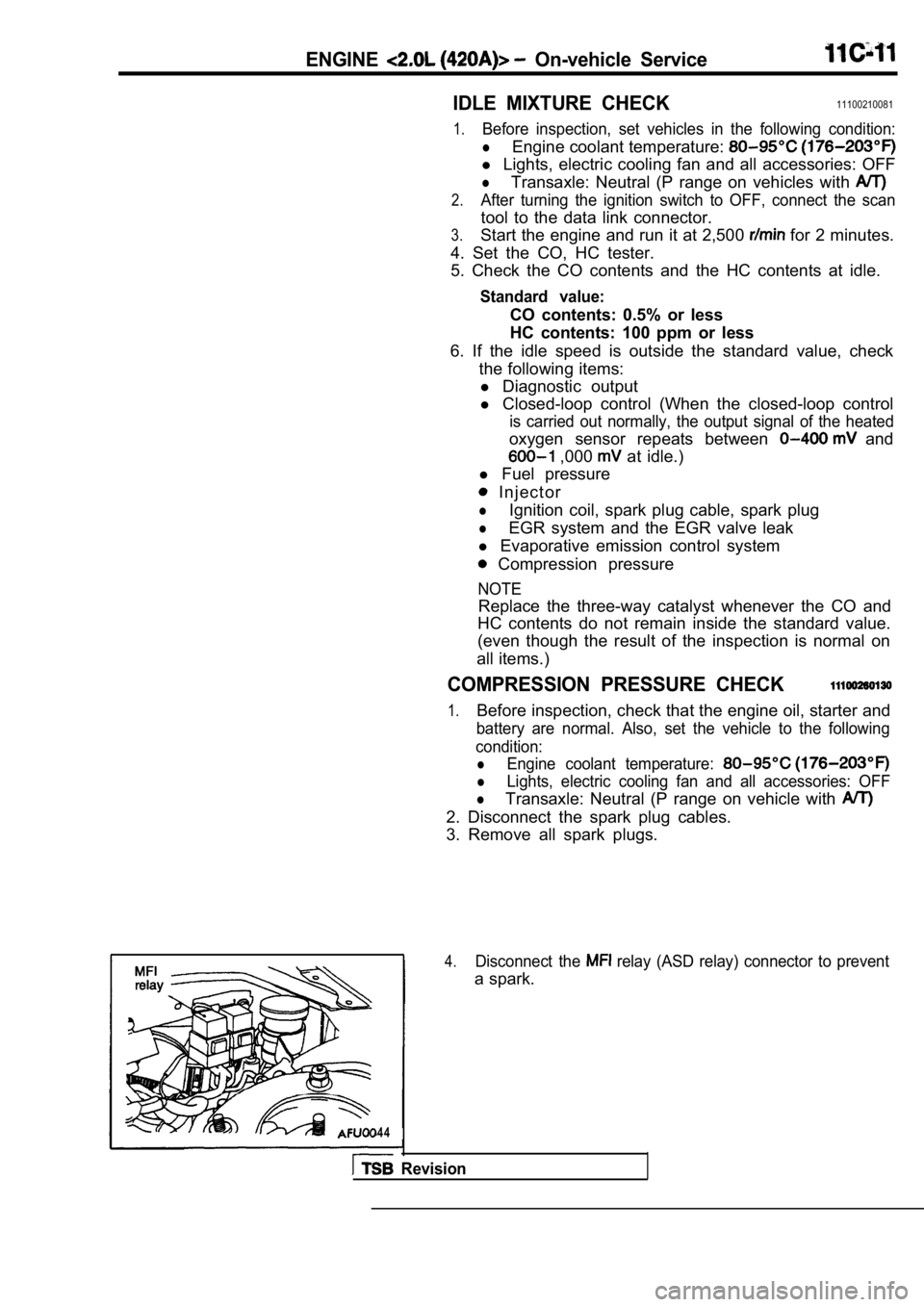
4.Disconnect the relay (ASD relay) connector to prevent
a spark.
4 4
Revision
Page 184 of 2103
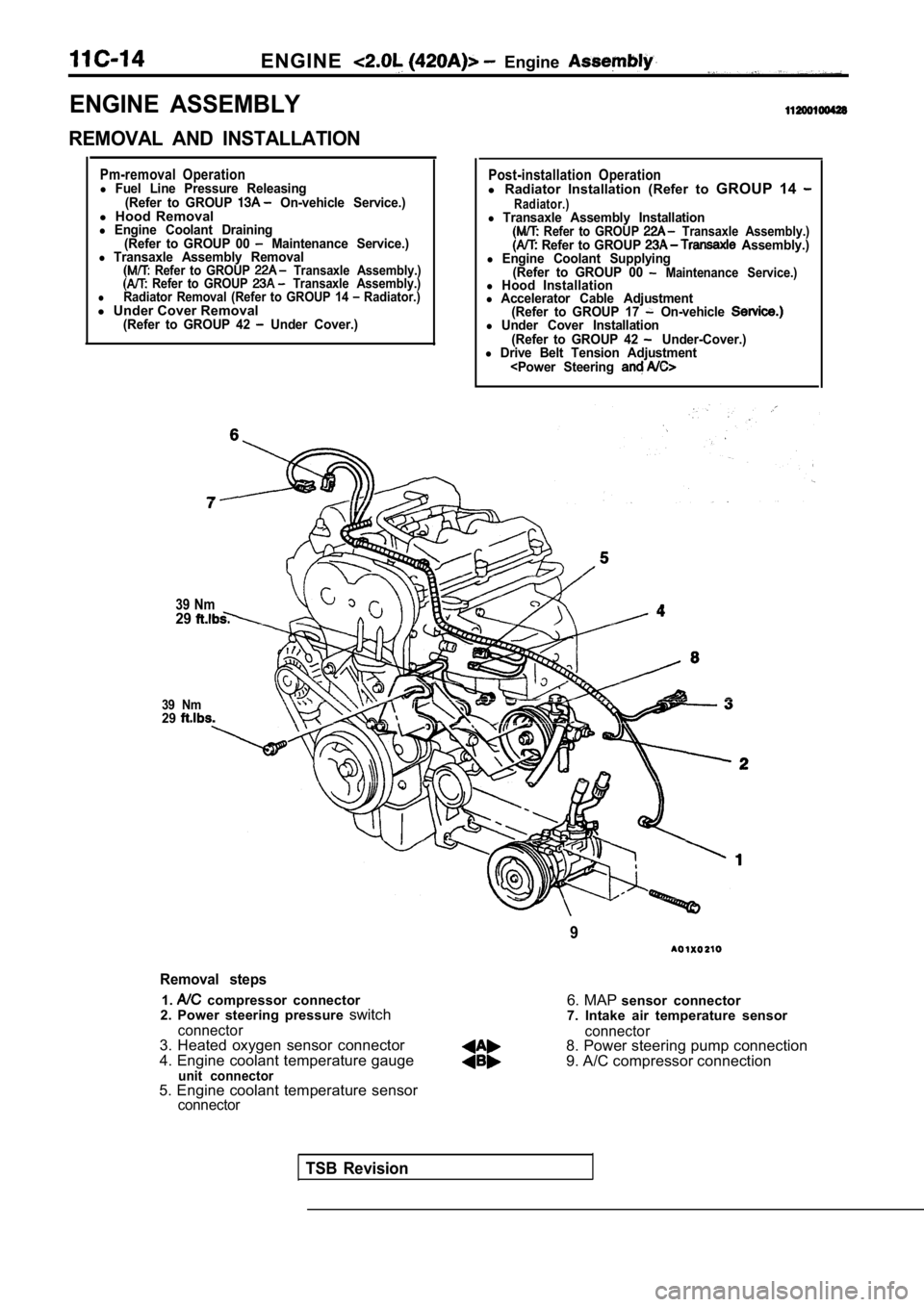
ENGINE Engine
ENGINE ASSEMBLY
REMOVAL AND INSTALLATION
Pm-removal Operationl Fuel Line Pressure Releasing(Refer to GROUP On-vehicle Service.)l Hood Removall Engine Coolant Draining
(Refer to GROUP 00 Maintenance Service.)l Transaxle Assembly Removal Refer to GROUP Transaxle Assembly.) Refer to GROUP Transaxle Assembly.)lRadiator Removal (Refer to GROUP 14 Radiator.)l Under Cover Removal(Refer to GROUP 42 Under Cover.)
39 Nm29
39 Nm29
Post-installation Operationl Radiator Installation (Refer to GROUP 14 Radiator.)l Transaxle Assembly Installation Refer to GROUP Transaxle Assembly.) Refer to GROUP Assembly.)l Engine Coolant Supplying
(Refer to GROUP 00 Maintenance Service.)l Hood Installationl Accelerator Cable Adjustment(Refer to GROUP 17 On-vehicle l Under Cover Installation
(Refer to GROUP 42 Under-Cover.)l Drive Belt Tension Adjustment
Removal steps
1. compressor connector
2. Power steering pressure switch
connector3. Heated oxygen sensor connector
4. Engine coolant temperature gauge
unit connector
6. MAP sensor connector
7. Intake air temperature sensor
connector8. Power steering pump connection
9. A/C compressor connection
5. Engine coolant temperature sensor
connector
TSB Revision
Page 185 of 2103
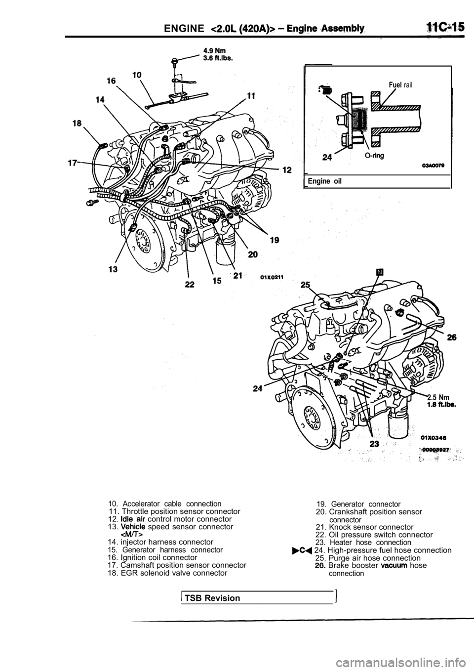
ENGINE
Fuelrail
Engine oil
2.5 Nm
10. Accelerator cable connection11. Throttle position sensor connector
12. control motor connector
13. speed sensor connector
14. injector harness connector
15. Generator harness connector16. Ignition coil connector
17. Camshaft position sensor connector 18. EGR solenoid valve connector
19. Generator connector20. Crankshaft position sensor
connector21. Knock sensor connector
22. Oil pressure switch connector
23. Heater hose connection 24. High-pressure fuel hose connection
25. Purge air hose connection
Brake booster hose
connection
TSB Revision
Page 191 of 2103
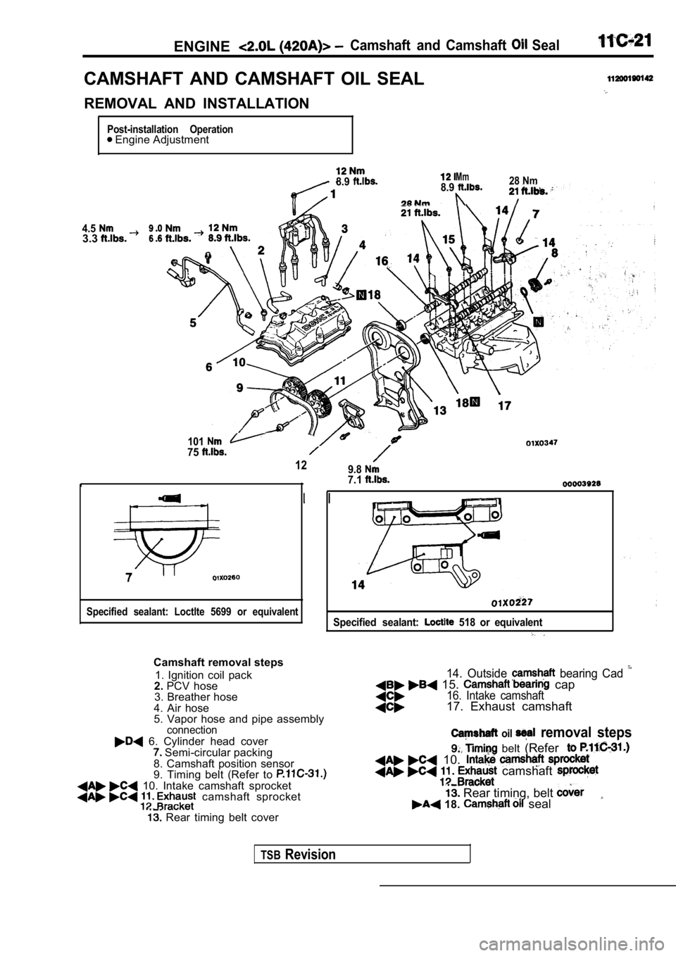
ENGINECamshaft and Camshaft Seal
CAMSHAFT AND CAMSHAFT OIL SEAL
REMOVAL AND INSTALLATION
Post-installation Operation Engine Adjustment
4.53.3
8.9Mm8.928 Nm
10175
129.8
7
Specified sealant: Loctlte 5699 or equivalent
7.1
Specified sealant: 518 or equivalent
Camshaft removal steps1. Ignition coil pack
2. PCV hose
3. Breather hose
4. Air hose
5. Vapor hose and pipe assembly
connection
6. Cylinder head cover Semi-circular packing
8. Camshaft position sensor
9. Timing belt (Refer to
10. Intake camshaft sprocket camshaft sprocket
Rear timing belt cover
14. Outside bearing Cad 15. cap16. Intake camshaft17. Exhaust camshaft
oil removal steps
belt (Refer
10. camshaft
Rear timing, belt 18. seal
TSBRevision
Page 199 of 2103
Cylinder Head
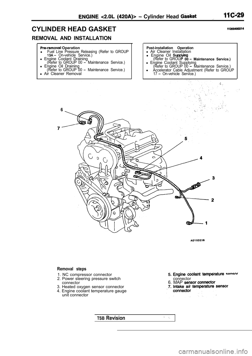
CYLINDER HEAD GASKET
REMOVAL AND INSTALLATION
Operation
lFuel Line Pressure Releasing (Refer to GROUP On-vehicle Service.)l Engine Coolant Draining(Refer to GROUP 00 Maintenance Service.)l Engine Oil Draining(Refer to GROUP 00 Maintenance Service.)l Air Cleaner Removal
6
Post-installation Operationl Air Cleaner Installationl Engine Oil (Refer to GROU00 Maintenance Service.)l Engine Coolant Supplying(Refer to GROUP 00 Maintenance Service.)lAccelerator Cable Adjustment (Refer to GROUP
17 On-vehicle Service.)
Removal steps
1. NC compressor connector
2. Power steering pressure switch
connector3. Heated oxygen sensor connector
4. Engine coolant temperature gauge unit connector
connector6. MAP
TSBRevision
Page 200 of 2103
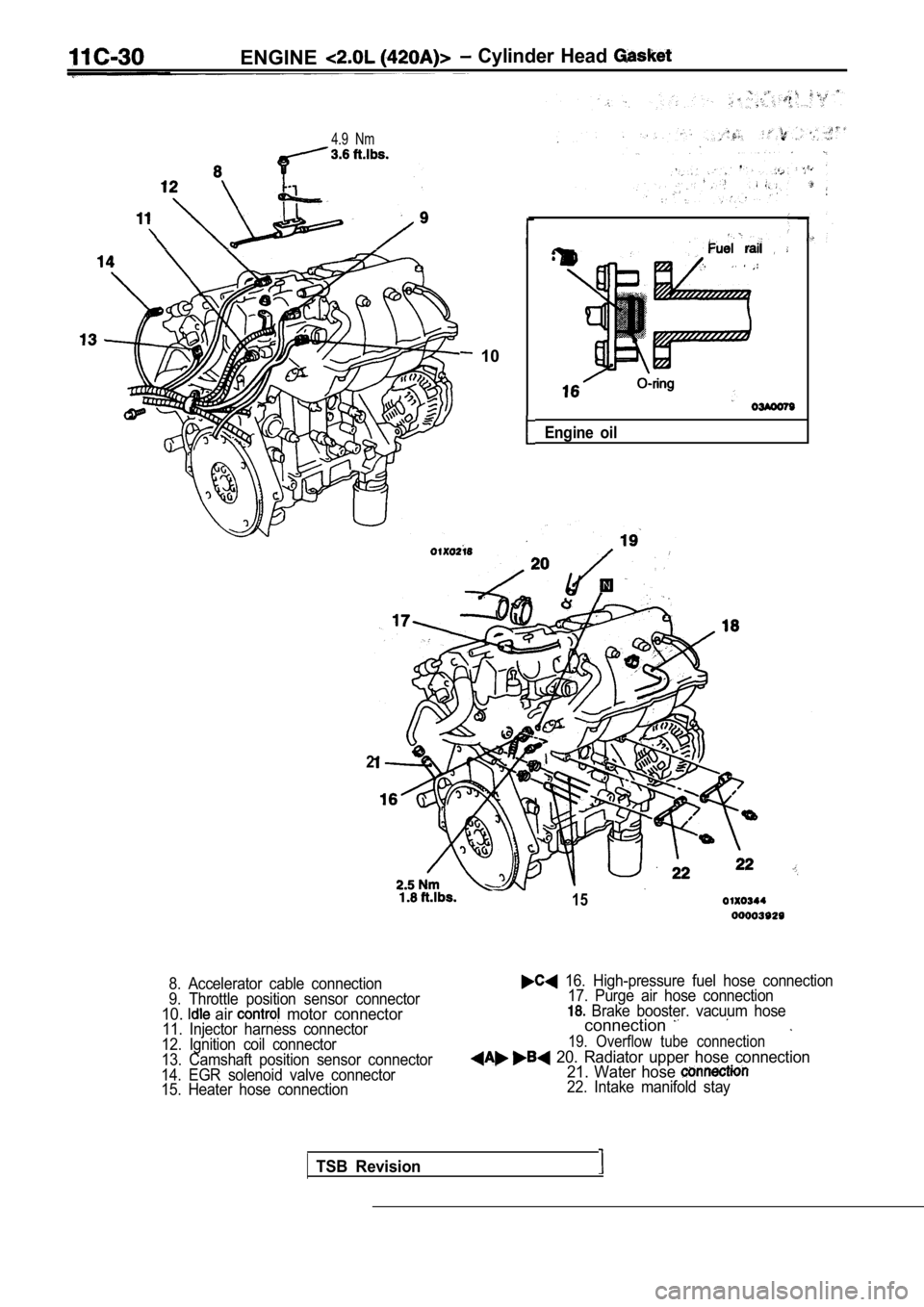
ENGINE Cylinder Head
4.9 Nm
10
Engine oil
TSB Revision
2
15
8. Accelerator cable connection
9. Throttle position sensor connector
10. air motor connector11. Injector harness connector
12. Ignition coil connector
13. Camshaft position sensor connector
14. EGR solenoid valve connector
15. Heater hose connection
16. High-pressure fuel hose connection 17. Purge air hose connection
Brake booster. vacuum hoseconnection
19. Overflow tube connection
20. Radiator upper hose connection 21. Water hose
22. Intake manifold stay
Page 212 of 2103
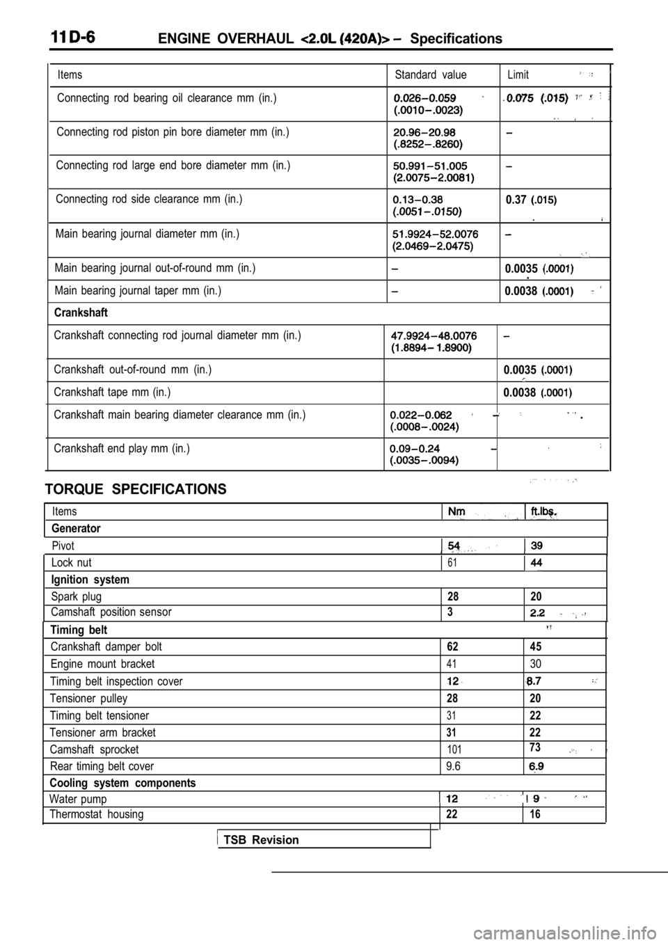
ENGINE OVERHAUL Specifications
Items
Connecting rod bearing oil clearance mm (in.)Standard value
Limit
Connecting rod piston pin bore diameter mm (in.)
Connecting rod large end bore diameter mm (in.)
Connecting rod side clearance mm (in.)
Main bearing journal diameter mm (in.)0.37
.
Main bearing journal out-of-round mm (in.)
Main bearing journal taper mm (in.)
Crankshaft
0.0035.
0.0038
Crankshaft connecting rod journal diameter mm (in.)
Crankshaft out-of-round mm (in.)
Crankshaft tape mm (in.)
Crankshaft main bearing diameter clearance mm (in.)0.0035
0.0038
.
Crankshaft end play mm (in.)
TORQUE SPECIFICATIONS
Items
Generator
Pivot
Lock nut61
Ignition system
Spark plug28 20
Camshaft position sensor3
Timing belt
Crankshaft damper bolt62 45
Engine mount bracket4130
Timing belt inspection cover
Tensioner pulley28 20
Timing belt tensioner3122
Tensioner arm bracket3122
Camshaft sprocket10173
Rear timing belt cover 9.6
Cooling system components
Water pump
Thermostat housing2216
TSB Revision
Page 213 of 2103
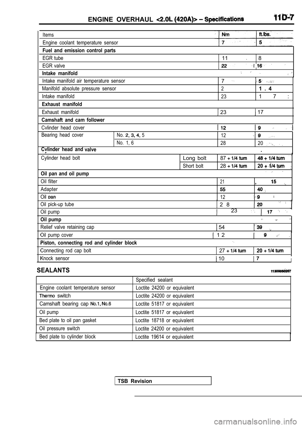
ENGINE OVERHAUL
Items
Engine coolant temperature sensor
Fuel and emission control parts
EGR tube
EGR valve
Intake manifold
11 8
Intake manifold air temperature sensor
Manifold absolute pressure sensor
Intake manifold
Exhaust manifold
Exhaust manifold
Camshaft and cam follower
Cvlinder head cover
Bearing head cover
No.5 12
No.1, 628 20
Cvlinder head and
valve.
7
21 . 4
231 7 :
23 17
Cylinder head bolt
Oil pan and oil pump
Oil filter
Adapter
Oil
Oil pick-up tube
Oil pump
Oil pump
Relief valve retaining cap
Long bolt87
Short bolt2820
21,
12
2 8
23
54
Oil pump cover
Piston, connecting rod and cylinder block
Connecting rod cap bolt
1 2
2720
Knock sensor 10I
SEALANTS
Engine coolant temperature sensor
switch
Camshaft bearing cap
Oil pump
Bed plate to oil pan gasket
Oil pressure switch Bed plate to cylinder block Specified sealant
Loctite 24200 or equivalent
Loctite 24200 or equivalent
Loctite 51817 or equivalent
Loctite 51817 or equivalent
Loctite 18718 or equivalent
Loctite 24200 or equivalent
Loctite 19614 or equivalent
TSB Revision