tow MITSUBISHI SPYDER 1990 Service Owner's Manual
[x] Cancel search | Manufacturer: MITSUBISHI, Model Year: 1990, Model line: SPYDER, Model: MITSUBISHI SPYDER 1990Pages: 2103, PDF Size: 68.98 MB
Page 280 of 2103
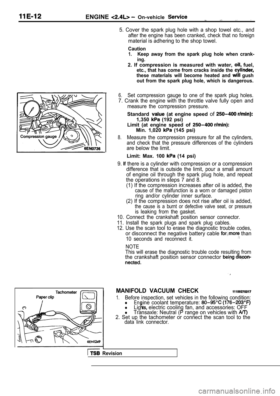
ENGINEOn-vehicle
5. Cover the spark plug hole with a shop towel etc., and
after the engine has been cranked, check that no foreign
material is adhering to the shop towel.
Caution
1.Keep away from the spark plug hole when crank-
ing.
2. If compression is measured with water, fuel,
etc., that has come from cracks inside the
these materials will become heated and gush
out from the spark plug hole, which is dangerous.
6.Set compression gauge to one of the spark plug hole s.
7. Crank the engine with the throttle valve fully open and
measure the compression pressure.
Standard (at engine speed of
1,350 (192 psi)
Limit (at engine speed of
Min. 1,020 (145 psi)
8.Measure the compression pressure for all the cylind ers,
and check that the pressure differences of the cyli nders
are below the limit.
Limit: Max. 100 (14 psi)
9. there is a cylinder with compression or a compression
difference that is outside the limit, pour a small amount
of engine oil through the spark plug hole, and repe at
the operations in steps 7 and 8.
(1) If the compression increases after oil is added , the
cause of the malfunction is a worn or damaged pisto n
ring and/or cylinder inner surface.
(2) If the compression does not rise after oil is added,
the cause is a burnt or defective valve seat, or pr essure
is leaking from the gasket.
10. Connect the crankshaft position sensor connecto r.
11. Install the spark plugs and spark plug cables.
12. Use the scan tool to erase the diagnostic troub le codes,
or disconnect the negative battery cable than
10 seconds and reconnect it.
NOTE
This will erase the diagnostic trouble code resulting from
the crankshaft position sensor connector
MANIFOLD VACUUM CHECK
1.Before inspection, set vehicles in the following co ndition:
lEn
lLig electric cooling fan, and accessories: OFF
ine coolant temperature:
lTransaxle: Neutral (P range on vehicles with
2. Set up the tachometer or connect the scan tool t o the
data link connector.
Revision
Page 287 of 2103
Engine Assembly
I N S T A L L A T I O N
ENGINE INSTALLATION
Install the engine while checking
hoses, and harness connectors are not clamped.
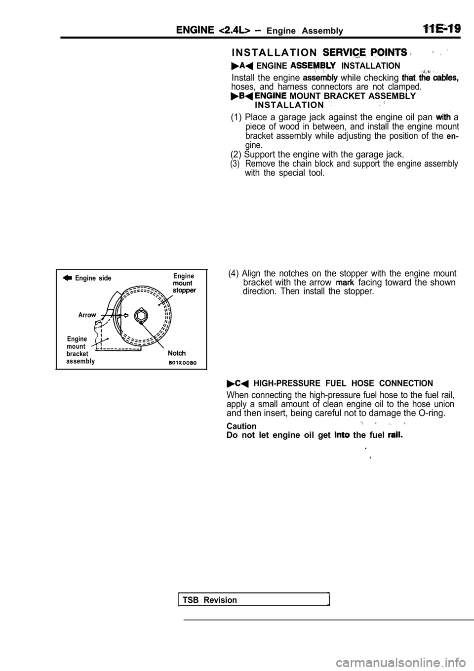
MOUNT BRACKET ASSEMBLY
I N S T A L L A T I O N
(1) Place a garage jack against the engine oil pan a
piece of wood in between, and install the engine mo unt
bracket assembly while adjusting the position of th e
en-
gine.
(2) Support the engine with the garage jack.
(3)Remove the chain block and support the engine assem bly
with the special tool.
Engine sideEngine
Arro
Engine
mount
bracket(4) Align the notches on the stopper with the engin e mount
bracket with the arrow facing toward the shown
direction. Then install the stopper.
assembly
HIGH-PRESSURE FUEL HOSE CONNECTION
When connecting the high-pressure fuel hose to the fuel rail,
apply a small amount of clean engine oil to the hos e union
and then insert, being careful not to damage the O-ring.
Caution
Do not let engine oil get the fuel
.
TSB Revision
Page 308 of 2103

ENGINE Timing Belt
TIMING BELT REMOVAL,,
Caution
If timing belt “B” is to be reused, use
it with an arrow on its flat side indicating the tu rning
direction (to the right).
CounterbalanceINSTALLATION SERVICE POINTS
TIMING BELT INSTALLATION
Install timing belt
by the procedure.
(1) Ensure that crankshaft sprocket “B” timing mark and the
counterbalance shaft sprocket timing mark are align ed.
(2) Fit timing belt
over crankshaft sprocket “B” and the
silent shaft sprocket. Ensure that there is no slac k in
the belt.
BELT TENSION ADJUSTMENT
Adjust the tension of timing belt by the following procedure.
(1) Temporarily fix the timing belt tensioner such that
the center of the tensioner pulley is to the left a nd above
the center of the installation bolt, and temporarily attach
the tensioner pulley so that the flange is toward t he front
of the engine.,
(2) Holding the timing belt “B” up with your
in the direction of the
belt so that the tension side of the belt is taut.
Now tighten
the bolt to fix the tensioner.. ,
Caution
When tightening the ensure that the
pulley shaft does not rotate, with
it to rotate with the bolt can
on the belt.
(3) Press the belt at the shown point by check
belt tension. If not,
S t a n d a r d v a l u e : 5 - 7 m m
. ,
TSB Revision
Page 345 of 2103
E N G I N E O V E R H A U L Cylinder Head and Valves
color
REMOVAL SERVICE
PRECAUTION FOR PARTS
Keep removed parts in order according to cylinder
and intake/exhaust.
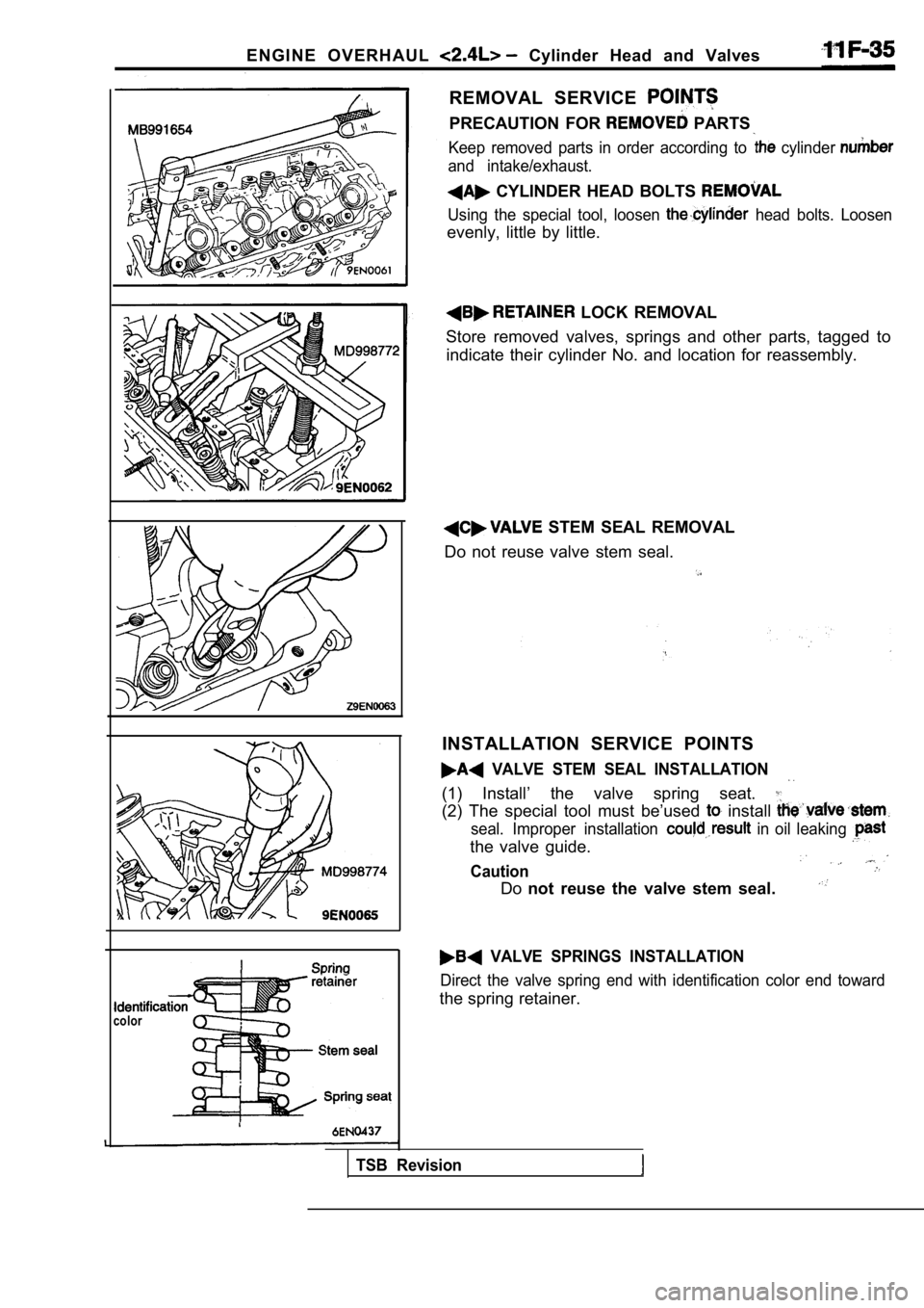
CYLINDER HEAD BOLTS
Using the special tool, loosen head bolts. Loosen
evenly, little by little.
LOCK REMOVAL
Store removed valves, springs and other parts, tagg ed to
indicate their cylinder No. and location for reasse mbly.
STEM SEAL REMOVAL
Do not reuse valve stem seal.
INSTALLATION SERVICE POINTS
VALVE STEM SEAL INSTALLATION
(1) Install’ the valve spring seat.
(2) The special tool must be’used install
seal. Improper installation in oil leaking
the valve guide.
Caution
Do not reuse the valve stem seal.
VALVE SPRINGS INSTALLATION
Direct the valve spring end with identification col or end toward
the spring retainer.
TSB Revision
Page 349 of 2103
ENGINE OVERHAUL Cylinder Head and Valves
Removalinstallation
Press
A
Press
A
Push rod
Valve
guide Push rod
Valve
guide
(2) Rebore the valve seat hole in the a
selected oversize valve seat diameter.
Intake seat ring hole diameters’
0.3 mm in.)
0.6
mm (1.3622-1.3634 in.)
Exhaust seat ring hole
0.3 mm in.)
0.6 O.S.
mm in.)
(3) Before fitting the valve seat, either heat the cylinder head
up to approximately
or cool the valve seat
in liquid nitrogen, to prevent the cylinder head bo re from
galling.
(4)Using a valve seat cutter, correct the valve seat t o the
specified width and angle.
See SEAT RECONDITIONINGPROCEDURE”.
VALVE GUIDE REPLACEMENT PROCEDURE
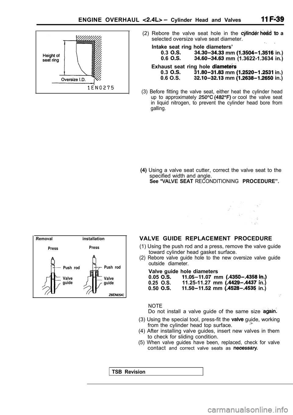
(1) Using the push rod and a press, remove the valv e guide
toward cylinder head gasket surface.
(2) Rebore valve guide hole to the new oversize val ve guide
outside diameter.
Valve guide hole diameters
0.05
0.25 O.S.
mm
0.50
11.25-11.27 mm in.)
mm in.)
NOTE
Do not install a valve guide of the same size
(3) Using the special tool, press-fit the guide, working
from the cylinder head top surface.
(4) After installing valve guides, insert new valve s in them
to check for sliding condition.
(5) When valve guides have been, replaced, check fo r valve
contactand correct valve seats as
TSB Revision
Page 517 of 2103
ENGINE (NON-TURBO)> Throttle Body
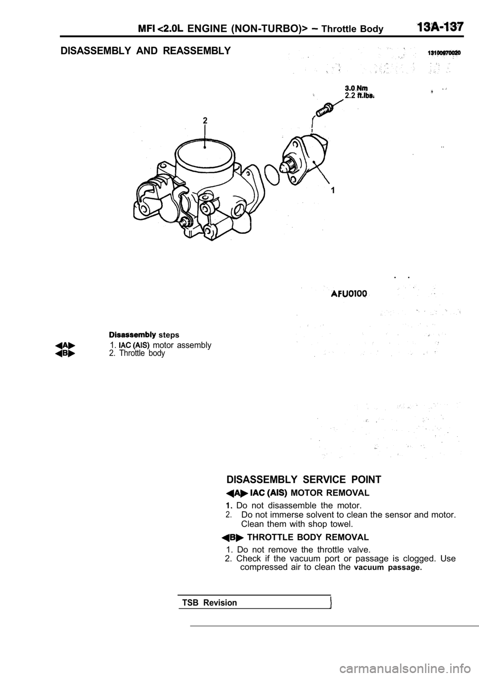
DISASSEMBLY AND REASSEMBLY
2.2
2I
. .
1. .
steps
1. motor assembly2. Throttle body
DISASSEMBLY SERVICE POINT
MOTOR REMOVAL
Do not disassemble the motor.
2.Do not immerse solvent to clean the sensor and moto r.
Clean them with shop towel.
THROTTLE BODY REMOVAL
1. Do not remove the throttle valve.
2. Check if the vacuum port or passage is clogged. Use
compressed air to clean the vacuum passage.
TSB Revision
Page 650 of 2103
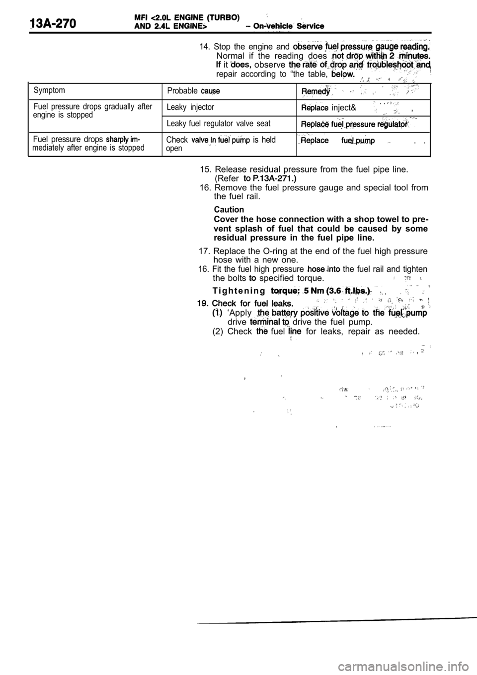
14. Stop the engine and
Normal if the reading does
it observe
repair according to “the table,
SymptomProbable
Fuel pressure drops gradually afterLeaky injector
engine is stopped inject&. . ,
Leaky fuel regulator valve seat
Fuel pressure drops Check is held. .mediately after engine is stopped open
15. Release residual pressure from the fuel pipe li ne.
(Refer
16. Remove the fuel pressure gauge and special tool from
the fuel rail.
Caution
Cover the hose connection with a shop towel to pre-
vent splash of fuel that could be caused by some residual pressure in the fuel pipe line.
17. Replace the O-ring at the end of the fuel high pressure
hose with a new one.
16. Fit the fuel high pressure the fuel rail and tighten
the bolts specified torque.
T i g h t e n i n g
‘Apply
drive drive the fuel pump.
(2) Check
fuel for leaks, repair as needed.
,
,
.
.
Page 673 of 2103
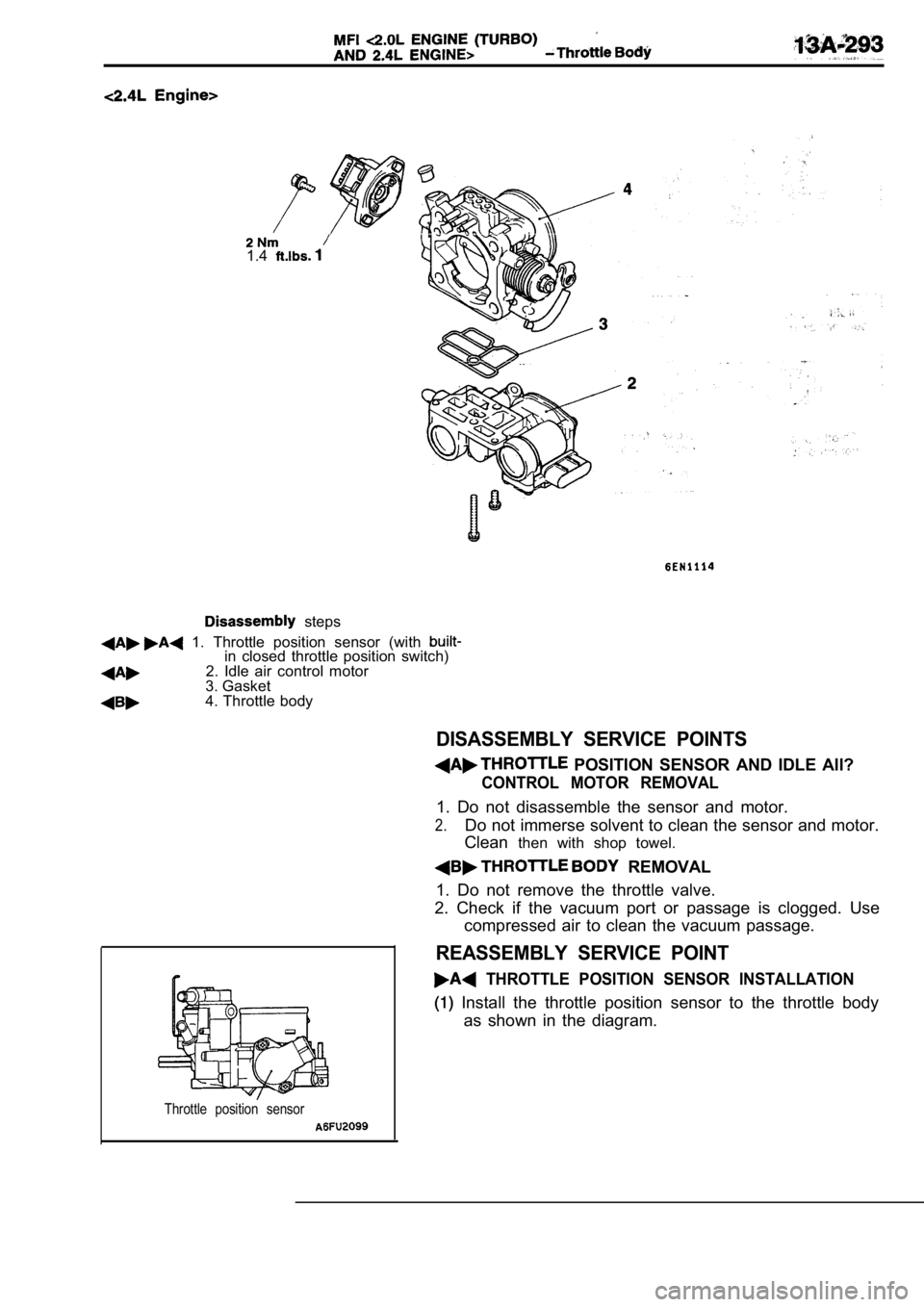
1.4
steps
1. Throttle position sensor (with in closed throttle position switch)2. Idle air control motor
3. Gasket
4. Throttle body
DISASSEMBLY SERVICE POINTS
POSITION SENSOR AND IDLE All?
CONTROL MOTOR REMOVAL
1. Do not disassemble the sensor and motor.
2.Do not immerse solvent to clean the sensor and moto r.
Clean then with shop towel.
REMOVAL
1. Do not remove the throttle valve.
2. Check if the vacuum port or passage is clogged. Use
compressed air to clean the vacuum passage.
REASSEMBLY SERVICE POINT
THROTTLE POSITION SENSOR INSTALLATION
Install the throttle position sensor to the thrott le body
as shown in the diagram.
Throttle position sensor
Page 689 of 2103

FUEL SUPPLY Fuel Filter.
REMOVAL SERVICE
P O I N T S
EYE BOLT REMOVAL
Hold the fuel filter with a spanner and remove the eye bolt.
Caution
As there will be some pressure remaining in the fue l
pipe line, coverit with a shop towel to prevent fuel from
spraying out.
FUEL MAIN PIPE DISCONNECTION
Hold the fuel filter with a spanner and loosen the flare nut.
Then disconnect the fuel main pipe.
TSB Revision
Page 723 of 2103
INTAKE AND EXHAUST Intake Manifold Engine ,
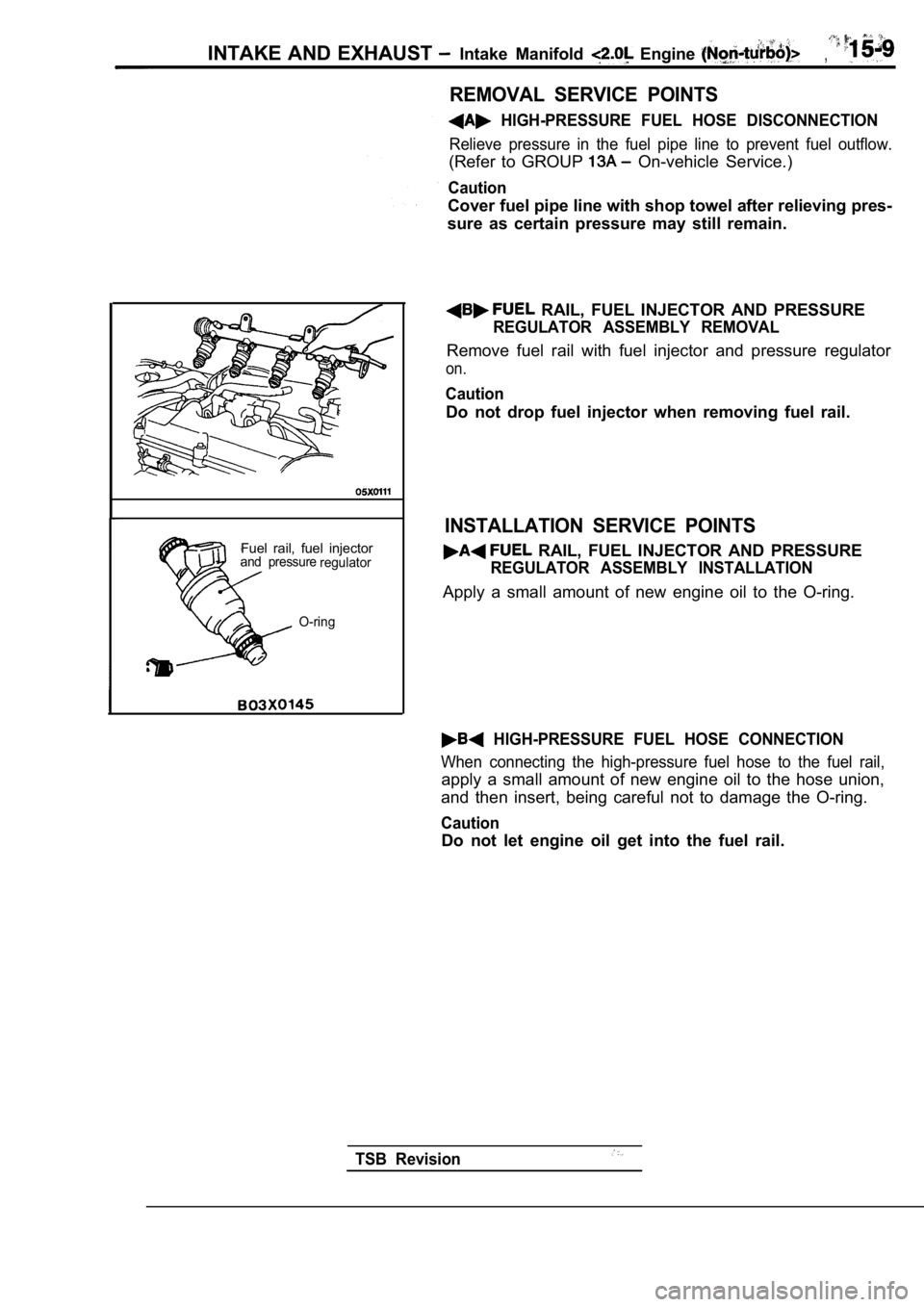
Fuel rail, fuel injectorand pressureregulator
O-ring
REMOVAL SERVICE POINTS
HIGH-PRESSURE FUEL HOSE DISCONNECTION
Relieve pressure in the fuel pipe line to prevent f uel outflow.
(Refer to GROUP On-vehicle Service.)
Caution
Cover fuel pipe line with shop towel after relievin g pres-
sure as certain pressure may still remain.
RAIL, FUEL INJECTOR AND PRESSURE
REGULATOR ASSEMBLY REMOVAL
Remove fuel rail with fuel injector and pressure re gulator
on.
Caution
Do not drop fuel injector when removing fuel rail.
INSTALLATION SERVICE POINTS
RAIL, FUEL INJECTOR AND PRESSURE
REGULATOR ASSEMBLY INSTALLATION
Apply a small amount of new engine oil to the O-rin g.
HIGH-PRESSURE FUEL HOSE CONNECTION
When connecting the high-pressure fuel hose to the fuel rail,
apply a small amount of new engine oil to the hose union,
and then insert, being careful not to damage the O- ring.
Caution
Do not let engine oil get into the fuel rail.
TSB Revision