tow MITSUBISHI SPYDER 1990 Service User Guide
[x] Cancel search | Manufacturer: MITSUBISHI, Model Year: 1990, Model line: SPYDER, Model: MITSUBISHI SPYDER 1990Pages: 2103, PDF Size: 68.98 MB
Page 145 of 2103
ENGINE OVERHAUL Cylinder Head and Valves,
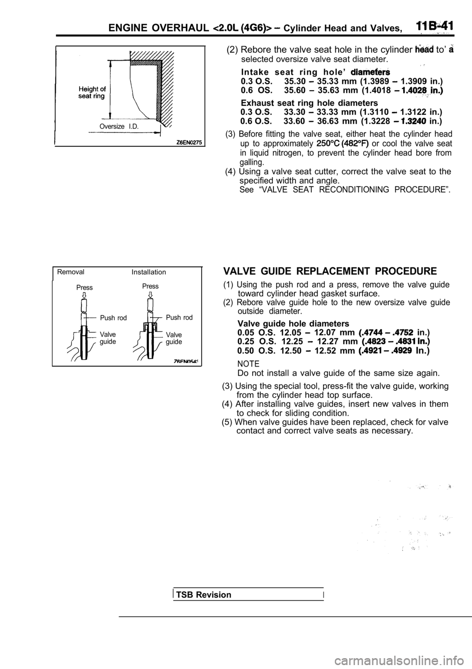
Oversize I.D.
RemovalInstallation
PressPress
Push rod
Valve
guide Push rod
Valve
guide
(2) Rebore the valve seat hole in the cylinder to’
selected oversize valve seat diameter.
I n t a k e s e a t r i n g h o l e ’
0.3 O.S. 35.30 35.33 mm (1.3989 1.3909 in.)
0.6 OS. 35.60
35.63 mm (1.4018
Exhaust seat ring hole diameters
0.3 O.S. 33.30
33.33 mm (1.3110 1.3122 in.)
0.6 O.S. 33.60
36.63 mm (1.3228 in.)
(3) Before fitting the valve seat, either heat the cylinder head
up to approximately
or cool the valve seat
in liquid nitrogen, to prevent the cylinder head bo re from
galling.
(4) Using a valve seat cutter, correct the valve seat to the
specified width and angle.
See “VALVE SEAT RECONDITIONING PROCEDURE”.
VALVE GUIDE REPLACEMENT PROCEDURE
(1) Using the push rod and a press, remove the valv e guide
toward cylinder head gasket surface.
(2) Rebore valve guide hole to the new oversize valve guide
outside diameter.
Valve guide hole diameters
0.05 O.S. 12.05
12.07 mm in.)
0.25 O.S. 12.25
12.27 mm
0.50 O.S. 12.50 12.52 mm In.)
NOTE
Do not install a valve guide of the same size again .
(3) Using the special tool, press-fit the valve gui de, working
from the cylinder head top surface.
(4) After installing valve guides, insert new valve s in them
to check for sliding condition.
(5) When valve guides have been replaced, check for valve
contact and correct valve seats as necessary.
TSB RevisionI
Page 182 of 2103
E N G I N E On-vehicle Service’
5. Cover the spark plug hole with a shop towel etc. , and
after the engine has been cranked, check that no foreign
material is adhering to the shop towel.
. Caution
1.Keep away from the spark plug hole when crank-
ing.
2. If compression is measured with water, oil, fuel ,
etc., that has come from cracks inside the cylinder ,
these materials will become heated and will gush
out from the spark plug hole, which is dangerous.
6.Set compression gauge to one of the spark plug hole s.
7. Crank the engine with the throttle valve fully o pen and
measure the compression pressure.
Standard value (at engine speed of
p s i )
Limit (at engine speed of
min. 689 (100 psi)
8.Measure the compression pressure for all the cylind ers,
and check that the pressure differences of the cylinders
are below the limit.
Limit:
NOTE
The limit value can be derived by calculating the d ifference
between the maximum and minimum values for the
compression pressure and dividing this value by the
maximum value.
9.If there is a cylinder with compression or a compre ssion
difference that is outside the limit, pour a small amount
of engine oil through the spark plug hole, and repeat
the operations in steps 7 and 8. (1) If the compression increases after oil is added , the
cause of the malfunction is a worn or damaged pisto n
ring and/or cylinder inner surface.
(2) If the compression does not rise after oil is a dded,
the cause is a burnt or defective valve seat, or pr essure
is leaking from the gasket.
10. Connect the
relay (ASD relay) connector.
11. Install the spark plug and spark plug cable.
12. Use the scan tool to erase the diagnostic troub le codes.
NOTE
This will erase the diagnostic trouble code resulti ng
the relay (ASD relay) being disconnected.
TSB Revision
Page 206 of 2103
ENGINE Belt
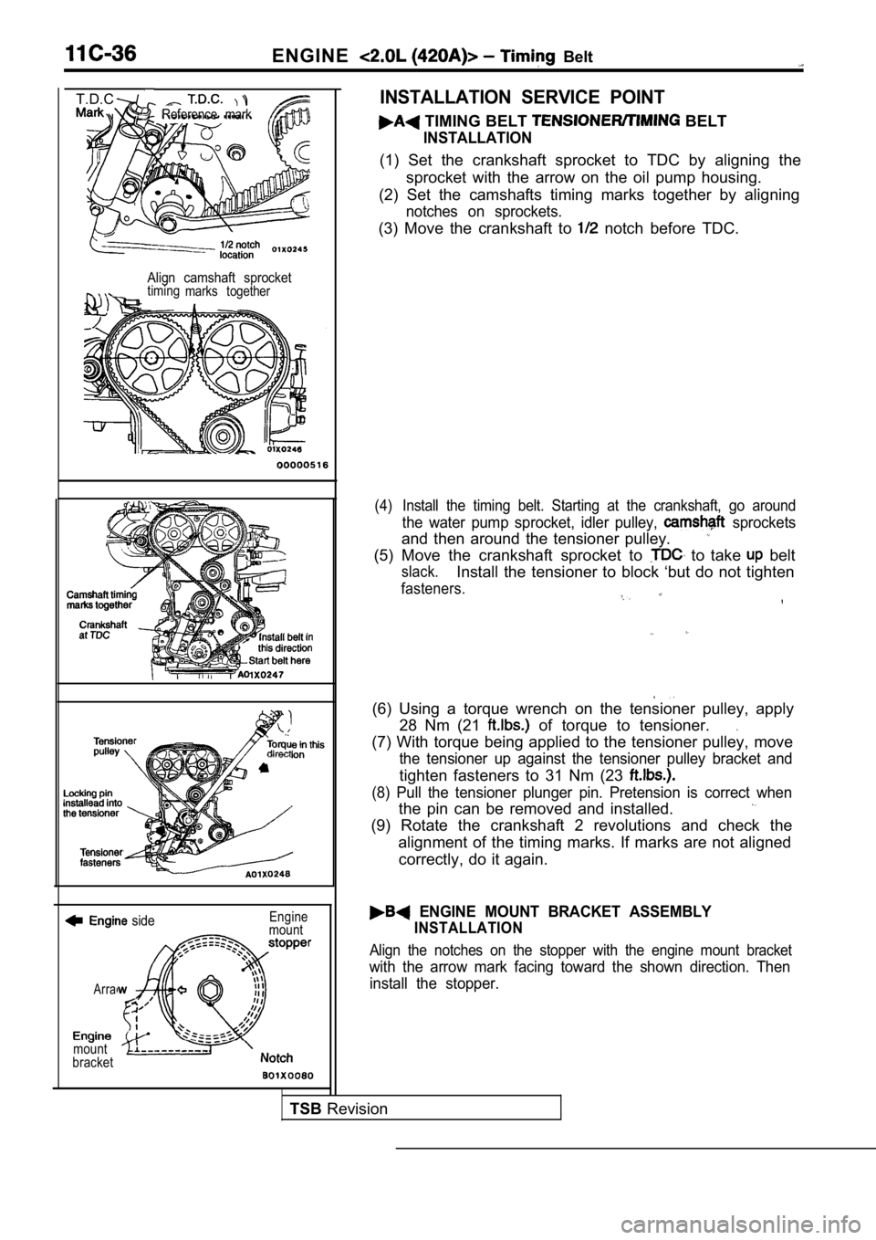
Reference mark
T.D.C.
Align camshaft sprockettimingmarks together
side
Arra
mount
bracket Engine
mount
INSTALLATION SERVICE POINT
TIMING BELT BELT
INSTALLATION
(1) Set the crankshaft sprocket to TDC by aligning the
sprocket with the arrow on the oil pump housing.
(2) Set the camshafts timing marks together by alig ning
notches on sprockets.
(3) Move the crankshaft to notch before TDC.
(4) Install the timing belt. Starting at the crankshaft, go around
the water pump sprocket, idler pulley, sprockets
and then around the tensioner pulley.
(5) Move the crankshaft sprocket to to take belt
slack.Install the tensioner to block ‘but do not tighten
fasteners.
(6) Using a torque wrench on the tensioner pulley, apply
28 Nm (21
of torque to tensioner..
(7) With torque being applied to the tensioner pull ey, move
the tensioner up against the tensioner pulley brack et and
tighten fasteners to 31 Nm (23
(8) Pull the tensioner plunger pin. Pretension is correct when
the pin can be removed and installed.
(9) Rotate the crankshaft 2 revolutions and check t he
alignment of the timing marks. If marks are not ali gned
correctly, do it again.
ENGINE MOUNT BRACKET ASSEMBLY
INSTALLATION
Align the notches on the stopper with the engine mo unt bracket
with the arrow mark facing toward the shown direction. Then
install the stopper.
TSB Revision
Page 214 of 2103
ENGINE OVERHAUL
FORM-IN-PLACE GASKETS
There are numerous places where form-in-place gaskets are used on the engine. Care must be
when applying form-in-place gaskets to assure obtaining the desired results. size, continuity, ‘and
location are of great importance. Too thin a bead can result in leakage
too much can result’ in
spill-over which can break off and obstruct fluid f eed lines.
A continuous bead of the proper width
essential to obtain a leak-free joint.
GASKET DISASSEMBLY
Parts assembled with form-in-place gaskets may be d isassembled without unusual effort’
it may be necessary to lightly tap the part with a mallet or other suitable tool to break the seal between
the mating surfaces.A flat gasket scraper may also be lightly tapped in to the joint but care be
taken not to damage the mating surfaces.
SURFACE PREPARATION
Scrape clean or wire brush all gasketsurfaces removing all loose material. Inspect
assure gasket rails are flat.
Flatten rails with a hammer on a flat plate if
must be free of oil and dirt. Make sure old gasket material is removed from blind
FORM-IN-PLACE GASKET APPLICATION
Assembling parts using a form-in-place gasket requires care but it’s easier than using precut gaskets.
Gasket material should be applied sparingly 1 mm
inch.) diameter or less to one
surface, Be certain the material surrounds each mou nting hole.
Excess material can easily be
‘off. Components should be torqued in place within 15 minutes. The use of a locating dowel is recommen ded
during assembly, to prevent smearing the material off location.
Loctite 18718 gasket material or equivalent should be applied in a continuous bead
3
mm
inch.) in diameter. All mounting holes must be circled.
For corner sealing, 3.17 or 6.35
mm
or inch.) drop is placed in the center of the gasket contact area. Uncured may
be removed with a shop towels. Components should be torqued in place while the sea lant
wet
to the touch (within 10 minutes). The usage of a locating dowel is recommended during assembly to
prevent smearing of material off location.
MOPAR TORQUE CURE GASKET MAKER
Mopar torque cure gasket maker is a unique anaerobi c type gasket material to be used ONLY
the and engine block. The material cures in the absenc e of air when. two
metallic surfaces. It will not cure if left in the uncovered tube. This anaerobic material
specially made
to seal the area between the
and cylinder block without disturbing the bearing’ or
alignment of these components.. .
TSB Revision
Page 220 of 2103
ENGINE OVERHAUL
.
INSTALLATION
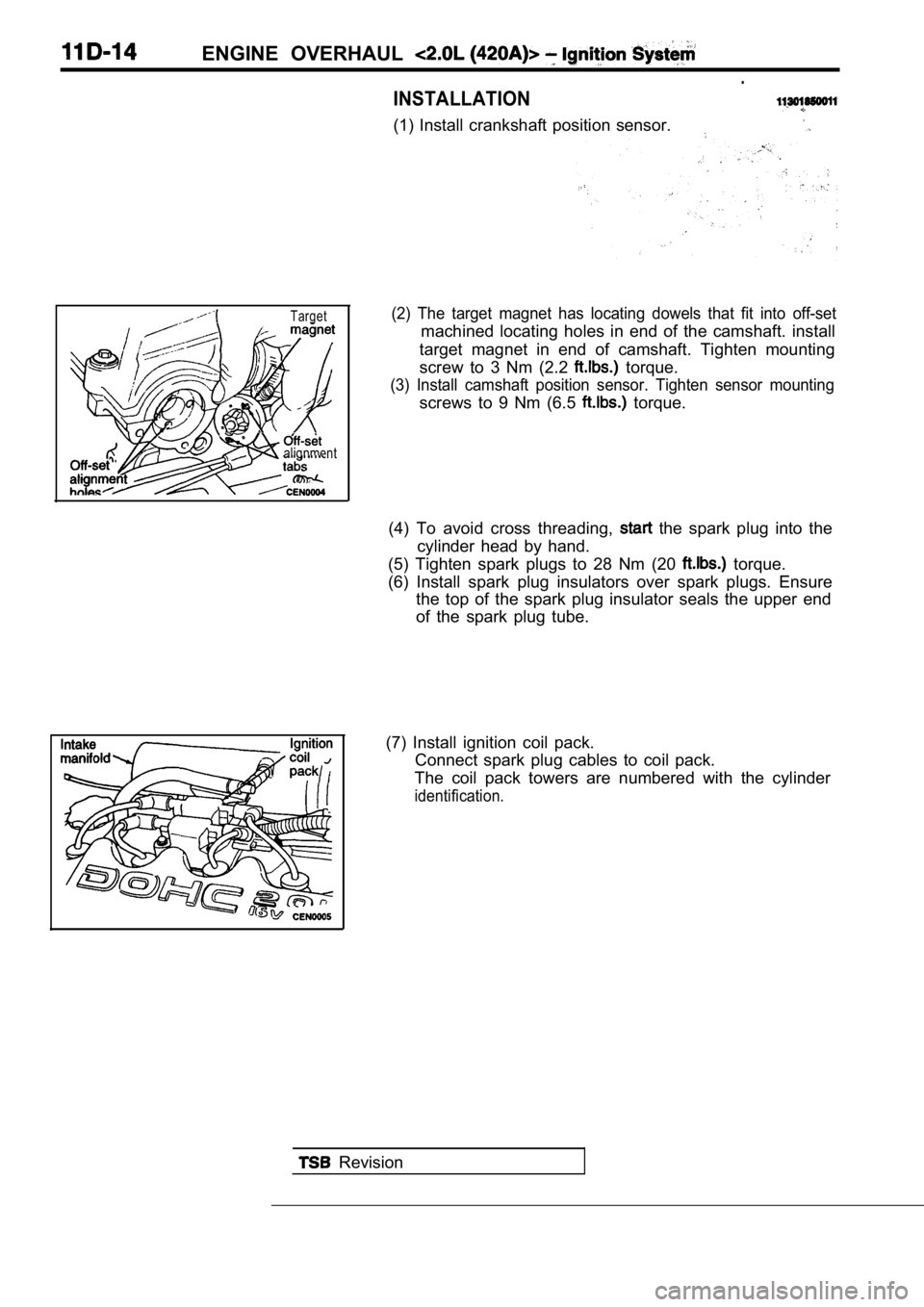
(1) Install crankshaft position sensor.
Target
alignment
(2) The target magnet has locating dowels that fit into off-set
machined locating holes in end of the camshaft. ins tall
target magnet in end of camshaft. Tighten mounting
screw to 3 Nm (2.2
torque.
(3) Install camshaft position sensor. Tighten senso r mounting
screws to 9 Nm (6.5 torque.
(4) To avoid cross threading,
the spark plug into the
cylinder head by hand.
(5) Tighten spark plugs to 28 Nm (20
torque.
(6) Install spark plug insulators over spark plugs. Ensure
the top of the spark plug insulator seals the upper end
of the spark plug tube.
(7) Install ignition coil pack. Connect spark plug cables to coil pack.
The coil pack towers are numbered with the cylinder
identification.
Revision
Page 221 of 2103

ENGINE OVERHAUL Ignition
INSPECTION
SPARK PLUG CABLE
(1)
must be between 3,000 to 12,000 ohms per
foot of cable. Replace any cable not within toleran ce.
IGNITION COIL
(1) Measure the primary
of each ‘At the coil,
connect an ohmmeter between the
and the pin
corresponding to the
in Resistance
on the primary side of
0.51
ohm. Replace the coil if resistance is
(2) Remove ignition cables from towers of’
the coil. Measure the
the coil
between the towers of each individual coil.
resistance should be ohms. the
coil if resistance is not within tolerance.
,
TSB Revision
Page 246 of 2103

11E N G I N E O V E R H A U L Oil Pan and Oil’
Revision
0057
(1) Apply Loctite 51817 to oil pump as shown in the figure.
Install oil-ring into the counter bore on the oil p ump body
discharge passage.
(2) oil pump slowly onto crankshaft until seated to
engine ‘block. Tighten fasteners to 23 Nm (17
(3) Install new seal by using Tool
(4) Place seal into opening with seal spring toward the inside
engine. Install seal until flush with cover.
(5) Install crankshaft sprocket using
bolt, washer and thrust bearing, from Special ‘Tool Kii
and Tool
,
.
(6) Install oil pick-up tube.
Page 255 of 2103
piston,
ENGINE
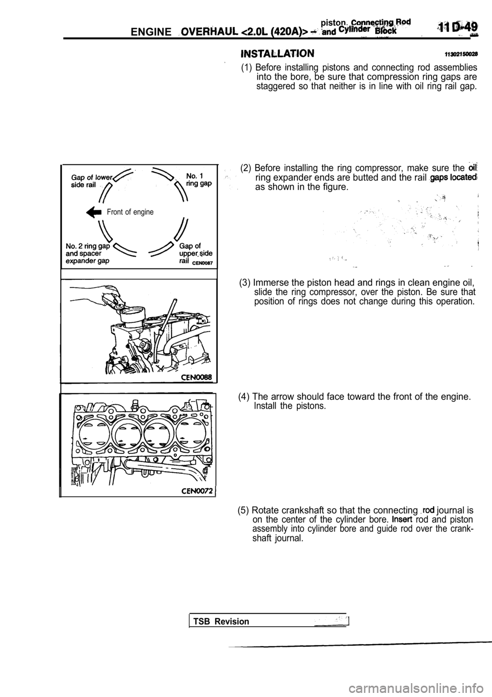
(1) Before installing pistons and connecting rod assemblies
into the bore, be sure that compression ring gaps a re
staggered so that neither is in line with oil ring rail gap.
Front of engine
(2) Before installing the ring compressor, make sur e the
ring expander ends are butted and the rail
as shown in the figure.
.
(3) Immerse the piston head and rings in clean engine oil,
slide the ring compressor, over the piston. Be sure that
position of rings does not change during this opera tion.
(4) The arrow should face toward the front of the engine.
Install the pistons.
(5) Rotate crankshaft so that the connecting journal is
on the center of the cylinder bore. rod and piston
assembly into cylinder bore and guide rod over the crank-
shaft journal.
TSB Revision
Page 260 of 2103
piston,
ENGINE OVERHAUL Cylinder Block
CONNECTING BEARING
(1) Place a piece of Plastigage across the, width of
bearing in the cap 6.35
mm off center and away -from the hole.
suspect areas can be checked, by placing in
the suspect area.
(2) Before assembling the rod with in place;
‘the crankshaft must be rotated the connecting rod
being checked starts moving toward the top of the e ngine.,
Only then should the cap be and torqued
to the specification.
Do not rotate the crankshaft while assembling the cap
or the Plastigage may be smeared, giving inaccurate re-
sults.
(3) Remove the bearing cap and compare the width of the
flattened Plastigage with the metric scale provided on
the package.
Standard value: mm in.)
Limit: 0.075 mm
in.)
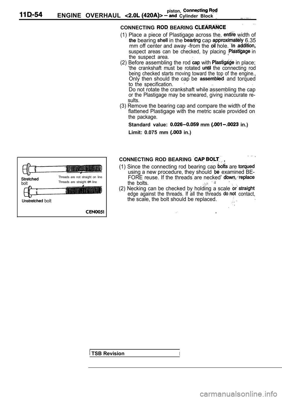
bolt
Threads are not straight on line
Threads are straight
line,
bolt
CONNECTING ROD BEARING ,
(1) Since the connecting rod bearing cap are
using a new procedure, they should examined BE-
FORE reuse. If the threads are necked’
the bolts.
(2) Necking can be checked by holding a scale
edge against the threads. If all the threads contact,
the scale, the bolt should be replaced. .
,
TSB RevisionI
Page 265 of 2103
ENGINE OVERHAUL
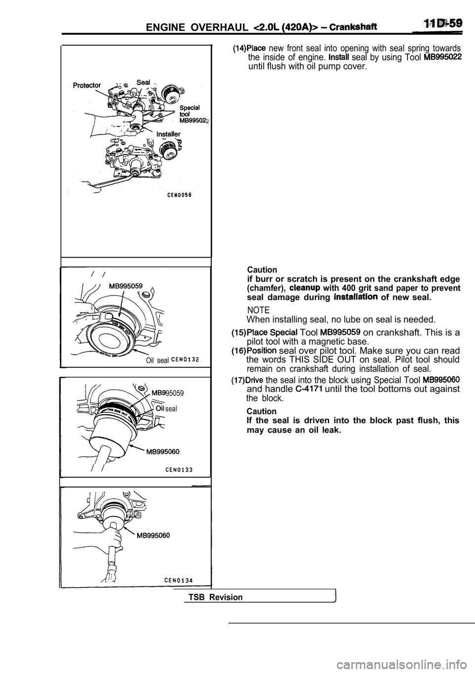
2
Oil seal
95059
seal
new front seal into opening with seal spring towards
the inside of engine. seal by using Tool
until flush with oil pump cover.
Caution
if burr or scratch is present on the crankshaft edge
(chamfer), with 400 grit sand paper to prevent
seal damage during of new seal.
NOTE
When installing seal, no lube on seal is needed.
Tool on crankshaft. This is a
pilot tool with a magnetic base.
seal over pilot tool. Make sure you can read
the words THIS SIDE OUT on seal. Pilot tool should
remain on crankshaft during installation of seal.
the seal into the block using Special Tool
and handle until the tool bottoms out against
the block.
Caution
If the seal is driven into the block past flush, this
may cause an oil leak.
TSB Revision