engine MITSUBISHI SPYDER 1990 Service Manual PDF
[x] Cancel search | Manufacturer: MITSUBISHI, Model Year: 1990, Model line: SPYDER, Model: MITSUBISHI SPYDER 1990Pages: 2103, PDF Size: 68.98 MB
Page 108 of 2103
![MITSUBISHI SPYDER 1990 Service Manual PDF ENGINE OVERHAUL
Items Standard value
Piston ring end gap mm (in.)
Piston pin O.D. mm (in.)
0 . 8
Oil 9 . 8
21
Piston pin press-in load (Ibs.)
[Room temperature]
Crankshaft pin MITSUBISHI SPYDER 1990 Service Manual PDF ENGINE OVERHAUL
Items Standard value
Piston ring end gap mm (in.)
Piston pin O.D. mm (in.)
0 . 8
Oil 9 . 8
21
Piston pin press-in load (Ibs.)
[Room temperature]
Crankshaft pin](/img/19/57345/w960_57345-107.png)
ENGINE OVERHAUL
Items Standard value
Piston ring end gap mm (in.)
Piston pin O.D. mm (in.)
0 . 8
Oil 9 . 8
21
Piston pin press-in load (Ibs.)
[Room temperature]
Crankshaft pin oil clearance mm (in.) 17,500
Connecting rod big end side clearance mm (in.)
Crankshaft, flywheel and drive plate
Bearing cap bolt shank length mm (in.)
0 . 4
Crankshaft end play mm (in.)
Crankshaft journal O.D. mm (in.) 0 . 2 5
57 (2.24)
pin O.D. mm (in.) 42 (1.77)
Crankshaft journal oil clearance mm (in.)
to cylinder clearance mm (in.)
0 . 1
block flatness of gasket surface mm (in.) 0.05 0.1
block grinding limit of gasket surface mm (in.)l 0.2‘Total resurfacing depth of both cylinder head and cylinder block
block overall height mm (in.)283.9-284.1
(11.177-11.185)
block I.D. mm (in.) 85.0 (3.35)
TSBRevision
REWORK DIMENSIONS
Items
Cylinder head and valve
Oversize rework dimensions of valve guide0.05 O.S.
hole (both intake and exhaust) mm (in.) 0.25 O.S.
0.50
Intake oversize rework 0.3
dimensions of valve seat hole mm (in.)
0.6 O.S.
Exhaust oversize rework dimensions of valve 0.3 O.S.
seat hole
mm (in.)0.6 O.S.
Crankshaft, flywheel and drive plate
Crankshaft out of roundness and taper of journal an d pin mm (in.)
Standard value
12.25-12.27 ,
,
Max. 0.01
NOTE
O.D.: Outer diameter
I.D.: Inner diameter
Oversize diameter
Page 109 of 2103
ENGINE OVERHAUL
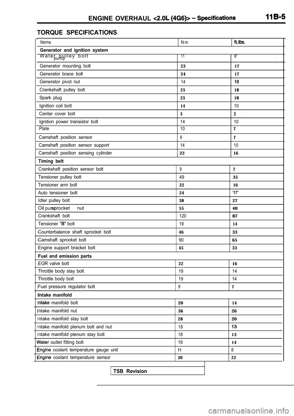
TORQUE SPECIFICATIONS
, ,
I
I I
I
I I
I
I
I I
Items
Generator and ignition system
W a t e r p u l l e y b o l tpump
Generator mounting bolt
Generator brace bolt
Generator pivot nut
Crankshaft pulley bolt
Spark plug
Ignition coil bolt
Center cover bolt Ignition power transistor bolt
Plate
Camshaft position sensor
Camshaft position sensor support
Camshaft position sensing cylinder
Timing belt
Crankshaft position sensor bolt
Tensioner pulley bolt
Tensioner arm bolt
Auto tensioner bolt Idler pulley bolt
Oil sprocket nutpump
Crankshaft bolt
Tensioner
bolt
Counterbalance shaft sprocket bolt
Camshaft sprocket bolt
Engine support bracket bolt
Fuel and emission parts
EGR valve bolt
Throttle body stay bolt
Throttle body bolt
Fuel pressure regulator bolt
Intake manifold
manifold bolt
ntake manifold nut ntake manifold stay bolt
ntake manifold plenum bolt and nut
ntake manifold plenum stay bolt
outlet fitting bolt
coolant temperature gauge unit
coolant temperature sensor
TSB Revision
N m
118”
23 17
2417
1410
25 18
25 18
1410
32
1410
107
97
14 10
2216
97
4935
22 16
24
‘17’
3827
5540
12087
1914
4633
9065
45 33
22 16
19 14
1914
97
2014
3626
2820
18
1813
1914
118
30 22
Page 111 of 2103
ENGINE OVERHAUL
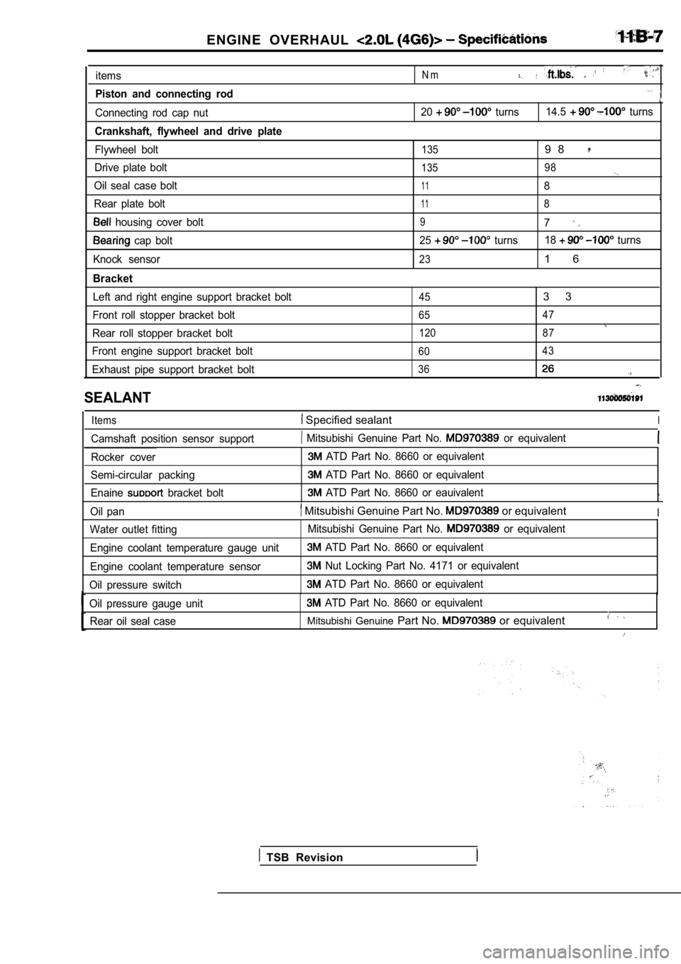
items
Piston and connecting rod
Connecting rod cap nut
Crankshaft, flywheel and drive plate
Flywheel bolt
Drive plate bolt
Oil seal case bolt
Rear plate bolt
housing cover bolt
cap bolt
Knock sensor
Bracket
Left and right engine support bracket bolt
Front roll stopper bracket bolt
Rear roll stopper bracket bolt
Front engine support bracket bolt
Exhaust pipe support bracket bolt
N m
20 turns 14.5 turns
1359 8
135 98
118
118
97
25 turns18 turns
231 6
453 3
65 47
120 87
60 43
36
SEALANT
Items Specified sealantI
Camshaft position sensor support Mitsubishi Genuine Part No. or equivalent
Rocker cover
Semi-circular packing
Enaine
bracket bolt
ATD Part No. 8660 or equivalent
ATD Part No. 8660 or equivalent
ATD Part No. 8660 or eauivalent
Oil pan Mitsubishi Genuine Part No. or equivalentI
Water outlet fitting
Engine coolant temperature gauge unit
Engine coolant temperature sensor
Oil pressure switch Mitsubishi Genuine Part No. or equivalent
ATD Part No. 8660 or equivalent
Nut Locking Part No. 4171 or equivalent
ATD Part No. 8660 or equivalent
Oil pressure gauge unit
ATD Part No. 8660 or equivalent
Rear oil seal case
Mitsubishi Genuine Part No. or equivalent
TSB Revision
Page 112 of 2103
ENGINE OVERHAUL ,
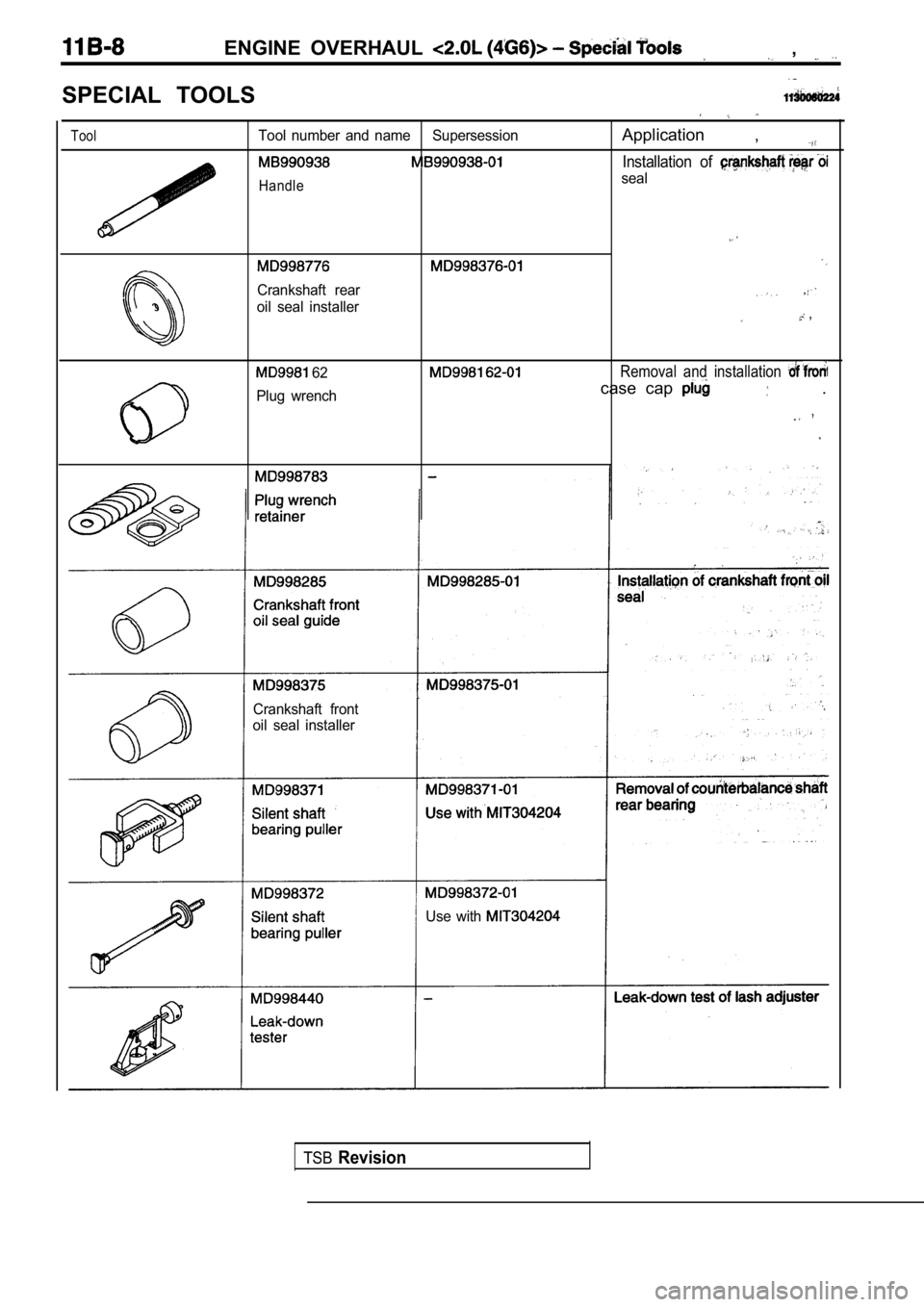
SPECIAL TOOLS
ToolTool number and name SupersessionApplication ,
Installation of
Handleseal
Crankshaft rear
oil seal installer ,
62Removal and installation
Plug wrenchcase cap .
Crankshaft front
oil seal installer
Use with
TSBRevision
Page 113 of 2103
ENGINE OVERHAUL
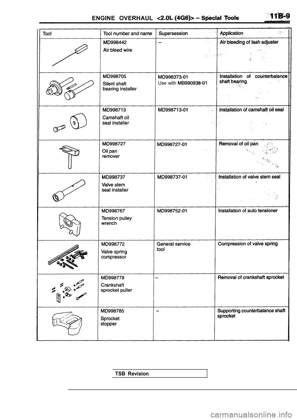
Use with
TSB Revision
Page 114 of 2103
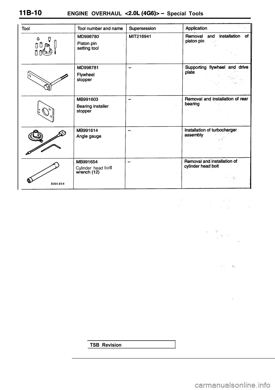
ENGINE OVERHAUL Special Tools
Cylinder headbolt
TSB Revision
Page 115 of 2103
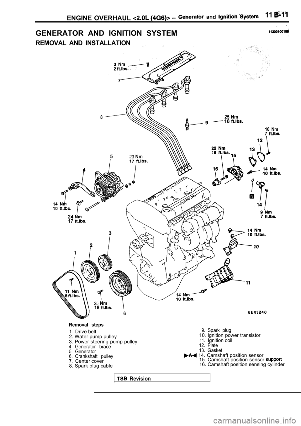
ENGINE OVERHAUL and 11
GENERATOR AND IGNITION SYSTEM
REMOVAL AND INSTALLATION
825 Nm 18
523Nm
24177
25Nm18
6
10 Nm7
Removal steps
1.Drive belt
2. Water pump pulley
3. Power steering pump pulley
4.Generator brace5.Generator6.Crankshaft pulley7.Center cover
8. Spark plug cable
9.Spark plug10. Ignition power transistor
11.Ignition coil12. Plate
13.Gasket 14. Camshaft position sensor 15. Camshaft position sensor
16. Camshaft position sensing cylinder
Revision
Page 116 of 2103
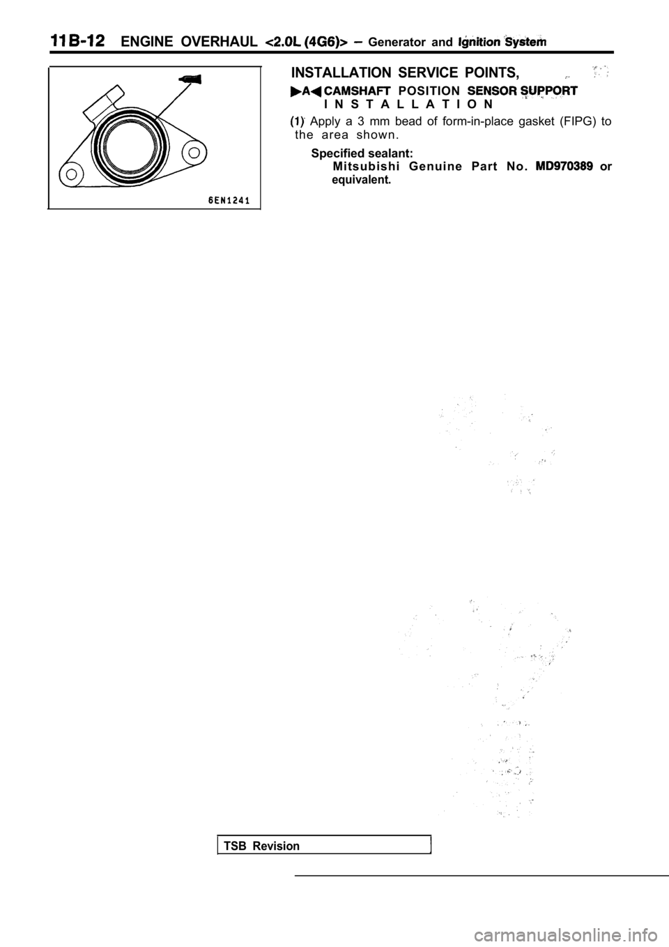
ENGINE OVERHAUL Generator and
INSTALLATION SERVICE POINTS,
POSITION
I N S T A L L A T I O N
Apply a 3 mm bead of form-in-place gasket (FIPG) to
t h e a r e a s h o w n .
Specified sealant: M i t s u b i s h i G e n u i n e P a r t N o .
or
equivalent.
TSB Revision
Page 117 of 2103
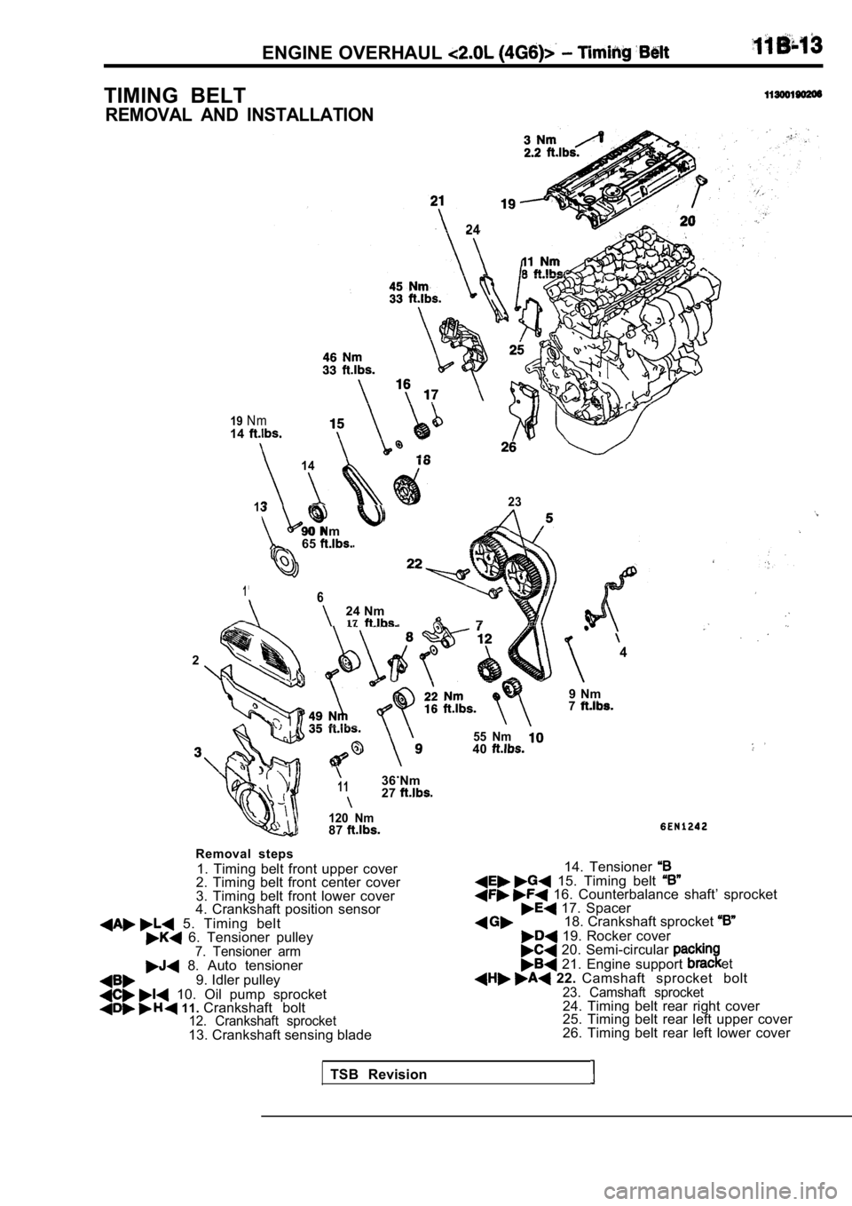
ENGINE OVERHAUL
TIMING BELT
REMOVAL AND INSTALLATION
19N m
24
14
14
13
90 Nm65
23
1624 Nm17
24
9 Nm7
.1136 Nm27
120 Nm87
Removal steps
1. Timing belt front upper cover
2. Timing belt front center cover
3. Timing belt front lower cover
4. Crankshaft position sensor
5. Timing belt 6. Tensioner pulley7. Tensioner arm 8. Auto tensioner
9. Idler pulley
10. Oil pump sprocket 11. Crankshaft bolt12. Crankshaft sprocket13. Crankshaft sensing blade
55 Nm40
14. Tensioner 15. Timing belt 16. Counterbalance shaft’ sprocket 17. Spacer18. Crankshaft sprocket
19. Rocker cover 20. Semi-circular
21. Engine support et
22. Camshaft sprocket bolt23. Camshaft sprocket24. Timing belt rear right cover
25. Timing belt rear left upper cover
26. Timing belt rear left lower cover
TSB Revision
Page 120 of 2103
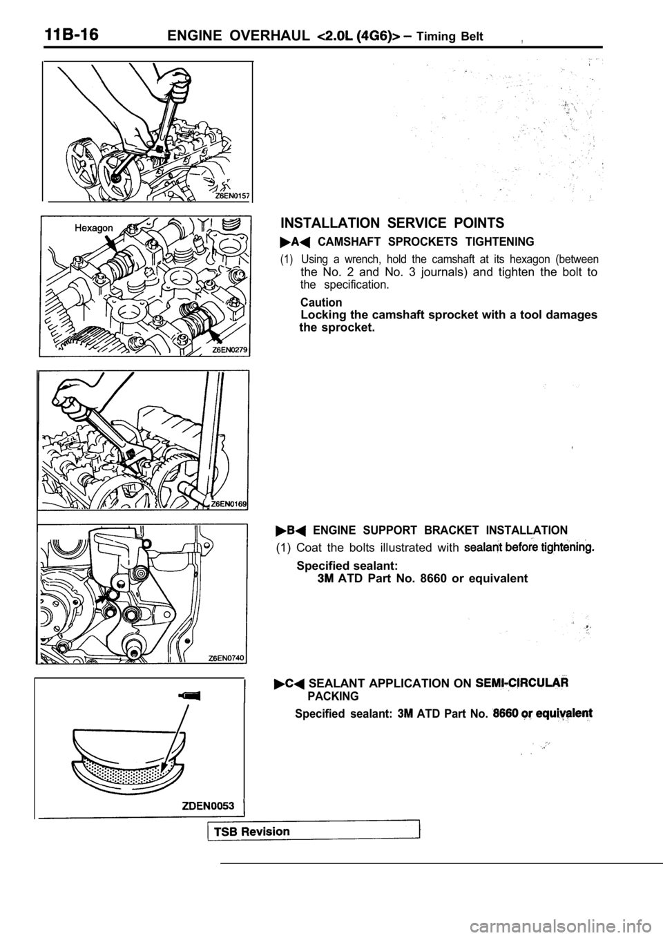
ENGINE OVERHAUL Timing Belt,
INSTALLATION SERVICE POINTS
CAMSHAFT SPROCKETS TIGHTENING
(1)Using a wrench, hold the camshaft at its hexagon (between
the No. 2 and No. 3 journals) and tighten the bolt to
the specification.
Caution
Locking the camshaft sprocket with a tool damages
the sprocket.
ENGINE SUPPORT BRACKET INSTALLATION
(1) Coat the bolts illustrated with
Specified sealant:
ATD Part No. 8660 or equivalent
SEALANT APPLICATION ON
PACKING
Specified sealant:
ATD Part No.