charging MITSUBISHI SPYDER 1990 Service Repair Manual
[x] Cancel search | Manufacturer: MITSUBISHI, Model Year: 1990, Model line: SPYDER, Model: MITSUBISHI SPYDER 1990Pages: 2103, PDF Size: 68.98 MB
Page 392 of 2103

ENGINE (NON-TURBO)> Troubleshooting.
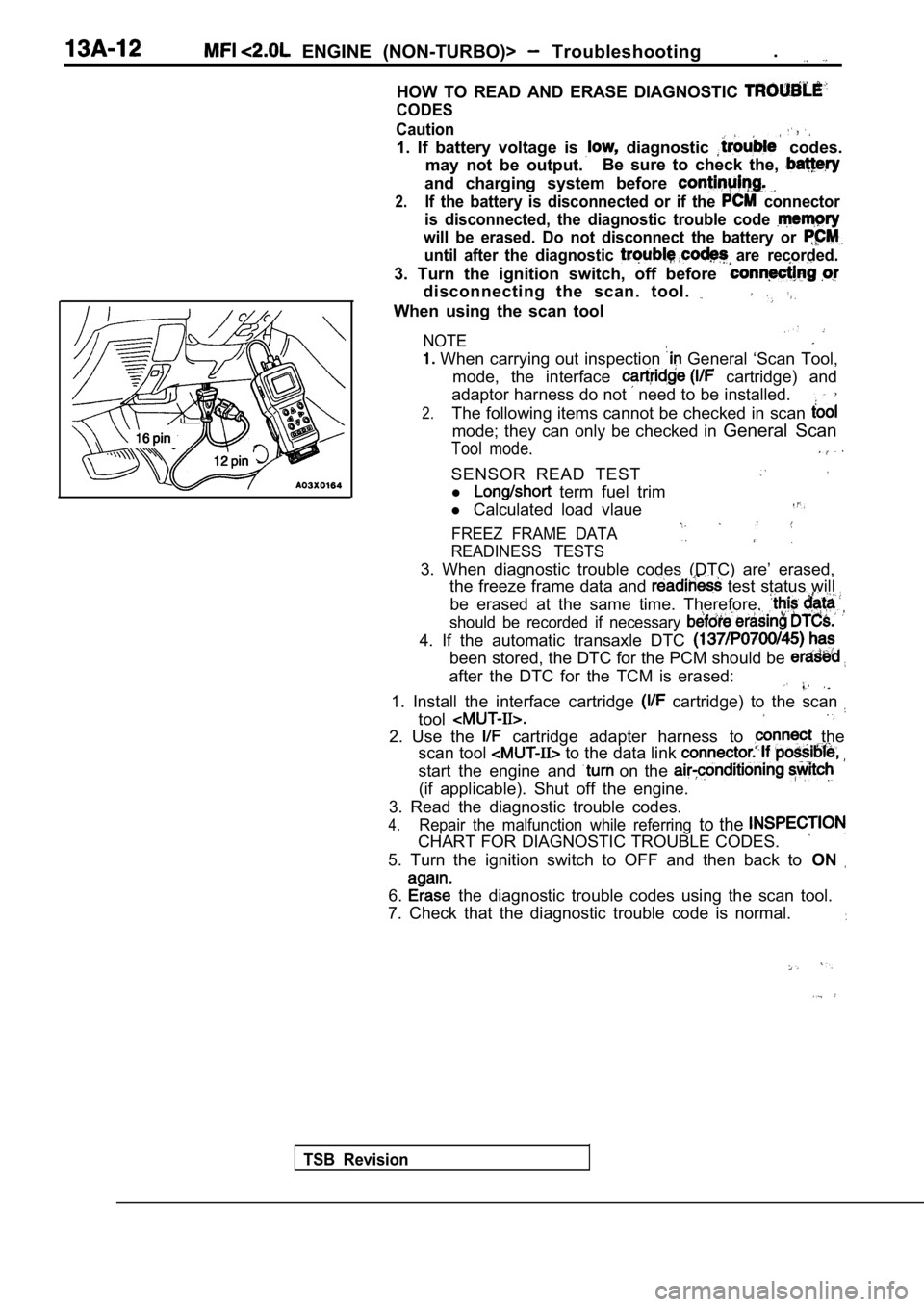
HOW TO READ AND ERASE DIAGNOSTIC
CODES
TSB Revision Caution
1. If battery voltage is diagnostic codes.
may not be output. Be sure to check the,
and charging system before
2.If the battery is disconnected or if the connector
is disconnected, the diagnostic trouble code
will be erased. Do not disconnect the battery or
until after the diagnostic are recorded.
3. Turn the ignition switch, off before
disconnecting the scan. tool.
When using the scan tool
NOTE
When carrying out inspection General ‘Scan Tool,
mode, the interface
cartridge) and
adaptor harness do not
need to be installed.
2.The following items cannot be checked in scan
mode; they can only be checked in General Scan
Tool mode.
SENSOR READ TEST
l term fuel trim
l Calculated load vlaue
FREEZ FRAME DATA
READINESS TESTS
3. When diagnostic trouble codes (DTC) are’ erased,
the freeze frame data and
test status will
be erased at the same time. Therefore,
should be recorded if necessary
4. If the automatic transaxle DTC
been stored, the DTC for the PCM should be
after the DTC for the TCM is erased:
1. Install the interface cartridge cartridge) to the scan
tool
2. Use the cartridge adapter harness to the
scan tool
to the data link
start the engine and on the
(if applicable). Shut off the engine.
3. Read the diagnostic trouble codes.
4.Repair the malfunction while referring to the
CHART FOR DIAGNOSTIC TROUBLE CODES.
5. Turn the ignition switch to OFF and then back to ON
6. the diagnostic trouble codes using the scan tool.
7. Check that the diagnostic trouble code is normal .
Page 398 of 2103

ENGINE (NON-TURBO)> Troubleshooting
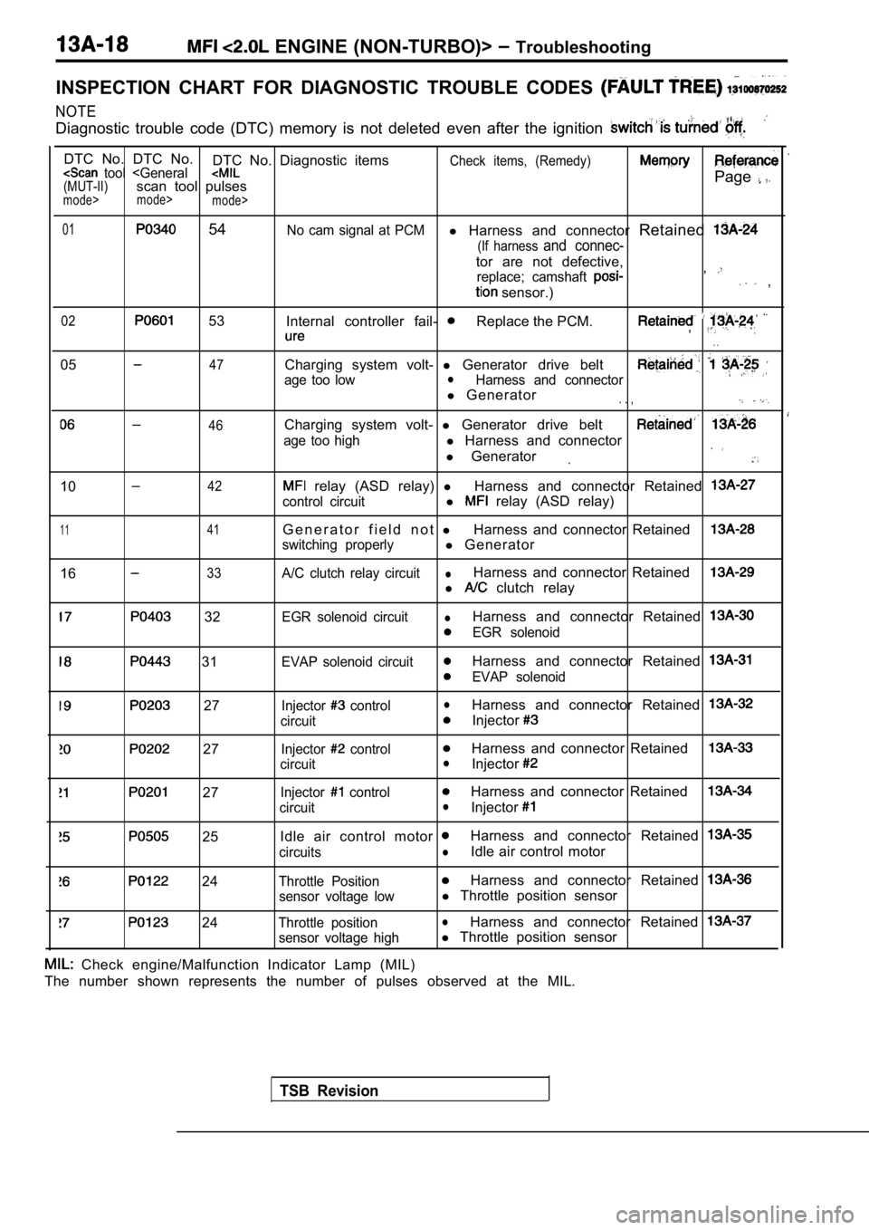
INSPECTION CHART FOR DIAGNOSTIC TROUBLE CODES
NOTE
Diagnostic trouble code (DTC) memory is not deleted even after the ignition
DTC No. DTC No.
DTC No. Diagnostic itemsCheck items, (Remedy) tool
mode>
mode>
01 54No cam signal at PCMl Harness and connector Retained
(If harness and connec-
tor are not defective,
replace; camshaft ,
sensor.) ,
02 53
Internal controller fail- Replace the PCM.,
. .
0547
46
Charging system volt- l Generator drive belt
age too lowlHarness and connector
l Generator. . ,
Charging system volt- l Generator drive belt
age too highl Harness and connector
l Generator
1042
1 141
1633
relay (ASD relay) lHarness and connector Retained
control circuitl relay (ASD relay)
G e n e r a t o r f i e l d n o t lHarness and connector Retained
switching properlyl Generator
A/C clutch relay circuitlHarness and connector Retained
l clutch relay
32
31
27
27
27
25
24
24
EGR solenoid circuitlHarness and connector Retained
EGR solenoid
EVAP solenoid circuit
Harness and connector Retained
EVAP solenoid
Injector
controllHarness and connector Retained
circuitInjector
Injector controlHarness and connector Retained
circuitlInjector
Injector controlHarness and connector Retained
circuitlInjector
Idle air control motor Harness and connector Retained
circuitslIdle air control motor
Throttle PositionHarness and connector Retained
sensor voltage lowl Throttle position sensor
Throttle positionlHarness and connector Retained
sensor voltage highl Throttle position sensor
TSB Revision
Check engine/Malfunction Indicator Lamp (MIL)
The number shown represents the number of pulses ob served at the MIL.
Page 405 of 2103
![MITSUBISHI SPYDER 1990 Service Repair Manual ENGINE (NON-TURBO)>
C h a r g i n g T o o
47
[Comment]
Background
The PCM tries to maintain charging system voltage of between and 15 volts.
l This code indicates:
The batte MITSUBISHI SPYDER 1990 Service Repair Manual ENGINE (NON-TURBO)>
C h a r g i n g T o o
47
[Comment]
Background
The PCM tries to maintain charging system voltage of between and 15 volts.
l This code indicates:
The batte](/img/19/57345/w960_57345-404.png)
ENGINE (NON-TURBO)>
C h a r g i n g T o o
47
[Comment]
Background
The PCM tries to maintain charging system voltage of between and 15 volts.
l This code indicates:
The battery voltage input is below the target charg ing voltage during engine
andNo significant change in voltage has been detected during active testing of the generator
output circuit.
Range of Check
lEngine speed: or more for approx. one minutelBattery positive voltage is at least 1 lower than the target charging voltage for approx.60 seconds.Set ConditionlBattery positive voltage does not change even if th e generator field current is cut off.
lDefects in generator or adjustmentl High resistance generatorl High between battery and
generator ground
l PCM
Check that the generator drive belt is properly in stalled. Repair
NG Measure the voltage between the generator terminal and the battery positive terminal. Engine: 1600 Headlight: High beam ON)
OK: Less than
Check the harness wire and terminal generator terminal and battery necessary.
NGMeasure the voltage between the generator body and battery Check the generator grounded line: neoative terminal. Engine: 1600 Headlight: High beam ON)
OK: Less than 0.5
OK
Measure at the generator lDisconnect the connector, and measure at the harnes s side.
SCAN TOOL Actuator test 10
relay (ASD relay) isturnedonandoff everyapprox. l Voltage between 1 and ground
[Measure when the relay (ASD relay) is turned on.]
OK: Battery positive voltage
NG Check the wire between generator relay
(ASD relay) connector. Repair, if necessary.
OK
Check the harness wire NG Repair connector.I
OK NG
SCAN TOOL SENSOR READ TEST (Data list) Check the harness wire between the PCM and the bat tery 10 Battery voltage as the ignition switch. Repair, if necessary.OK: indicated on the scan tool and actual positive
Check trouble symptom.
TSB RevisionI
Page 406 of 2103
![MITSUBISHI SPYDER 1990 Service Repair Manual ENGINE (NON-TURBO)> Troubleshooting
Scan tool 06
General scan tool Charging System Voltage Too
.High
46
[Comment]
Background Generator internal shorted
l The PCM tries to maintain MITSUBISHI SPYDER 1990 Service Repair Manual ENGINE (NON-TURBO)> Troubleshooting
Scan tool 06
General scan tool Charging System Voltage Too
.High
46
[Comment]
Background Generator internal shorted
l The PCM tries to maintain](/img/19/57345/w960_57345-405.png)
ENGINE (NON-TURBO)> Troubleshooting
Scan tool 06
General scan tool Charging System Voltage Too
.High
46
[Comment]
Background Generator internal shorted
l The PCM tries to maintain charging system voltage o f between 13.2 and 15 volts.l
Generator field driver shorted to ‘ground l PCM failedlThis code indicates that the battery voltage input is above the target charging voltage
during engine operation and PCM efforts to regulate the generator field do not prevent
the voltage from rising.
Range of Check
lEngine speed: 1500 or more for approx. one minute
Set Condition ,
lBattery positive voltage is at least higher than target charging voltage for approx. 12seconds.
SCAN TOOL SENSOR READ TEST (Data list)
36 Charging system goal
OK:
or more
Replace the PCM.
SCAN TOOL SENSOR
(Data list)as well as me ignitionswitch. necessary.OK: on the scan tool and actual battery positivelCheck the wire between the PCM and ground.
voltage are the same. Repair, if necessary.
OK
, NG
tor. and if necessary.
Measure at the generator connector Repair megeneralDisconnect the connector and measure at the equipme nt side.l Continuity between 2 and generator body.
OK: No continuity
I
OK
Check me following NG Repair
OK
Check trouble symptom.
Check the harness wire
NG
OK
Repair
Replace the PCM.
TSB
Page 433 of 2103
![MITSUBISHI SPYDER 1990 Service Repair Manual ENGINE (NON-TURBO)>
NG Replace
Scan tool 62
Code General scan tool Upstream Shorted to Volt;
No.
21
[Comment]l Heated oxygen sensor failedBackgroundl W i r i n glUpstream heated MITSUBISHI SPYDER 1990 Service Repair Manual ENGINE (NON-TURBO)>
NG Replace
Scan tool 62
Code General scan tool Upstream Shorted to Volt;
No.
21
[Comment]l Heated oxygen sensor failedBackgroundl W i r i n glUpstream heated](/img/19/57345/w960_57345-432.png)
ENGINE (NON-TURBO)>
NG Replace
Scan tool 62
Code General scan tool Upstream Shorted to Volt;
No.
21
[Comment]l Heated oxygen sensor failedBackgroundl W i r i n glUpstream heated oxygen sensor requires a heater cir cuit for proper operation.
l PCM,
l The heater circuit is supplied with battery voltage through the
relay relay):lA failure in the sensors heater circuit prevents it from providing accurate data to the PCM.l the PCM monitors more than 1.2 volts, the sensor h as shorted to heater circuit voltage.Range of Checkl Two or more minutes after the engine startsl Engine coolant temperature: or moreSet Conditionl Heated oxygen sensor output voltage is more than 1. 2 for 3 seconds.
OK
OKNG Repair
Check trouble symptom.
NGNGCheck the harness wire between the PCM and the heat ed oxygen Repairsensor (front).
OK
Replace the PCM.
Scan tool 68
Code General scan tool PCM Failure
No. Communications
53
[Comment]Set Condition
l There is no communication between in the control module.
Probable cause
l PCM failed
the PCM.
Probable cause
[Comment] BackgroundlBattery temperature input is used to adjust the gen erator charging rate based upon the
ambient temperature around the battery.
Range of Check
l
switch: ON
Set Condition
lThe sensor voltage is not within the acceptable ran ge of 0.3 to 4.9 volts for 3 seconds
or more. l
Battery temperature sensor failed
l PCM failed
Replace the PCM.
TSB Revision
Page 457 of 2103
![MITSUBISHI SPYDER 1990 Service Repair Manual ENGINE Troubleshooting
[Comment]
Background
lThe fuel level sensor, which is installed in the fuel tank, informs the PCM of fuel level(amount).lThe PCM does not carry out a MITSUBISHI SPYDER 1990 Service Repair Manual ENGINE Troubleshooting
[Comment]
Background
lThe fuel level sensor, which is installed in the fuel tank, informs the PCM of fuel level(amount).lThe PCM does not carry out a](/img/19/57345/w960_57345-456.png)
ENGINE Troubleshooting
[Comment]
Background
lThe fuel level sensor, which is installed in the fuel tank, informs the PCM of fuel level(amount).lThe PCM does not carry out a specific monitor when the fuel amount is small
or large.
Range of Check
l Battery positive voltage: 13
15 l Engine is running
Set Conditions
The fuel level signal does not change according to the fuel consumption by driving.Probable cause
l
Fuel level sensor failed
l PCM failed
Check the fuel gauge unit and its circuit.
(Refer to GROUP 54 Combination Meters.)
OK
N GCheck the following connectors: A-l 06 Repair
OK
Check trouble symptom.
N G
N G
Check the harness wire between the PCM and fuel lev el sensor Repairconnector.
OK
Replace the PCM.
Scan tool 153
Code General scan tool Battery Temperature Sensor
No.Voltage Too LowI
44
[Comment]
Background
Battery temperature input is used to adjust the gen erator charging rate based upon the ambient
temperature around the battery.
Range of Check
Ignition switch: ON
Set Conditions
The sensor voltage remains less than 0.3
for 3 seconds.
l Battery temperature sensor l PCM
Replace the
TSB Revision
Page 458 of 2103
![MITSUBISHI SPYDER 1990 Service Repair Manual E N G I N E
Scan tool 154
C o d e G e n e r a l s c a n t o o l T e m p e r a t u r e S e n s o r
No.Voltage Too High
44
[Comment]
Backgroundl Battery temperature sensor l PCM MITSUBISHI SPYDER 1990 Service Repair Manual E N G I N E
Scan tool 154
C o d e G e n e r a l s c a n t o o l T e m p e r a t u r e S e n s o r
No.Voltage Too High
44
[Comment]
Backgroundl Battery temperature sensor l PCM](/img/19/57345/w960_57345-457.png)
E N G I N E
Scan tool 154
C o d e G e n e r a l s c a n t o o l T e m p e r a t u r e S e n s o r
No.Voltage Too High
44
[Comment]
Backgroundl Battery temperature sensor l PCM failedBattery temperature input is used to adjust the gen erator charging rate based upon the ambienttemperature around the battery.Range of CheckIgnition switch: ON
Set Conditions .
The sensor voltage remains more than 4.9 for 3 seconds.
Replace the PCM.
Scan tool 155
C o d e G e n e r a l s c a n t o o l U p s t r e a m S h o r t e d t o
No. G r o u n d
[Comment]
Background
lWhen the heated oxygen sensor temperature is low, t
he sensor has the same electrical
characteristics as an insulator.
lThe heated oxygen sensor output signal line is rest ricted to That is why the line voltageis approx. when the heated oxygen sensor temperature is low.lIf the heated oxygen sensor output signal line is grounded, its voltage will become low.
Range of Check
l Engine coolant temperature when the engine starts:
or less
l Within three seconds after the engine
Set Conditions
The heated oxygen sensor output signal line is or less.
TSB Revision
l
.
Upstream, heated oxygen sensor failed
Wiring harness and connectors failed PCM failed
NGCheck the harness wire between the PCM and upstream heated Repair
oxygen sensor connector.
OK
Replace the PCM.
Page 493 of 2103

ENGINE (NON-TURBO)>
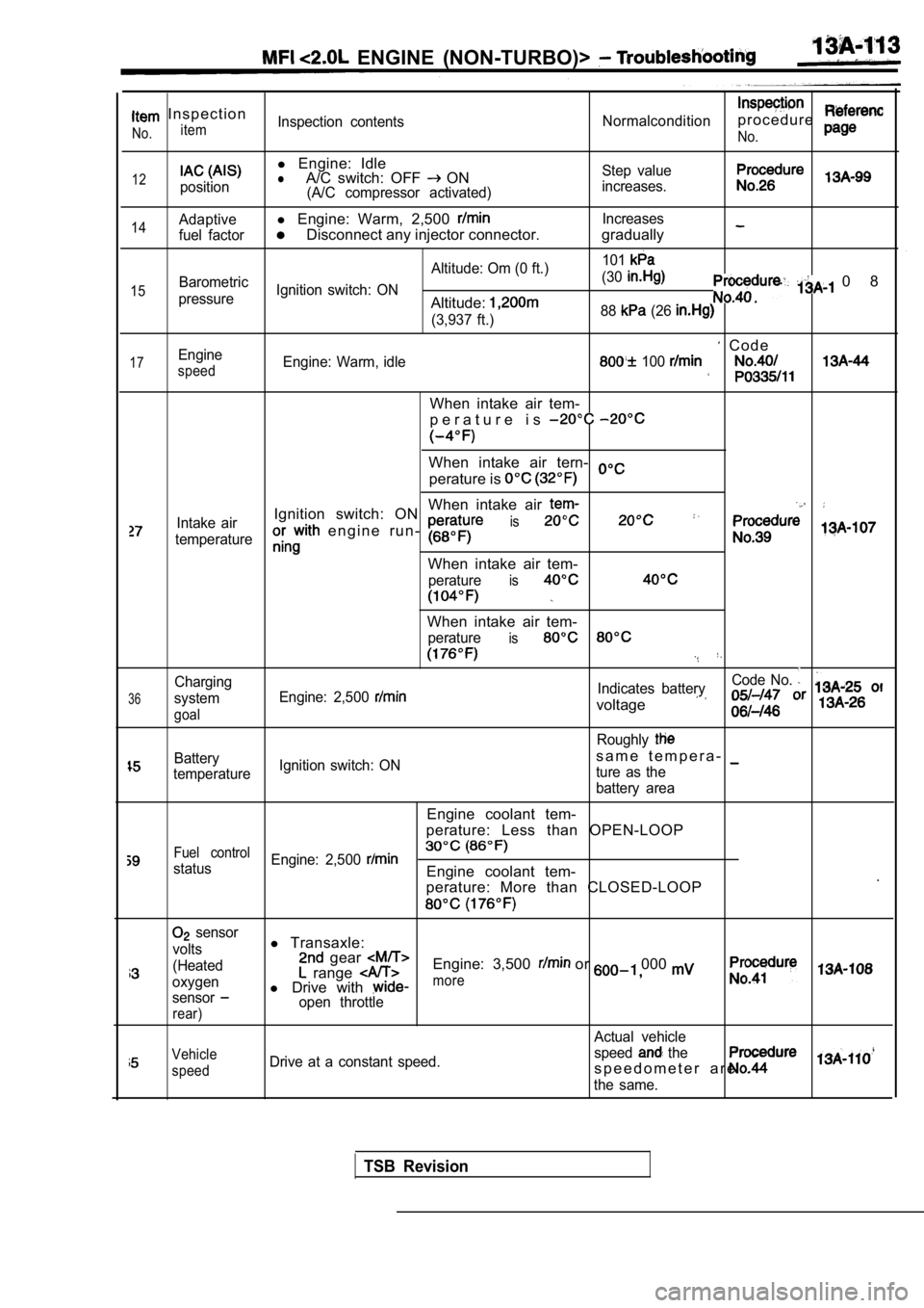
I n s p e c t i o n
itemNo.Inspection contentsNormalconditionp r o c e d u r e
No.
12position
l Engine: IdlelA/C switch: OFF ON(A/C compressor activated) Step value
increases.
14
15
17
Adaptivel Engine: Warm, 2,500 Increases
fuel factor
Disconnect any injector connector. gradually
Altitude: Om (0 ft.) 101Barometric
Ignition switch: ON (30
pressureAltitude:
0 8
(3,937 ft.)
88 (26
C o d eEngine
speedEngine: Warm, idle 100
When intake air tem-
p e r a t u r e i s
When intake air tern-
perature is
When intake air
Intake airIgnition switch: ON
e n g i n e r u n - is
temperature
When intake air tem-
peratureis
36
Charging
system
goal
When intake air tem-
peratureis
Code No.
Engine: 2,500 Indicates battery
voltage
Roughly
Batterys a m e t e m p e r a -
temperature Ignition switch: ON
ture as the
battery area
Engine coolant tem-
perature: Less than OPEN-LOOP
Fuel control
status Engine: 2,500 Engine coolant tem-
.
perature: More than CLOSED-LOOP
sensor
volts
(Heated
oxygen
sensor
rear)
l Transaxle: gear Engine: 3,500 or 000 range l Drive with more
open throttle
Actual vehicle
Vehicle
speedDrive at a constant speed. speed the
s p e e d o m e t e r a r e .
the same.
TSB Revision
Page 536 of 2103

ENGINE (TURBO)
AND
ENGINE> T r o u b l e s h o o t i n g
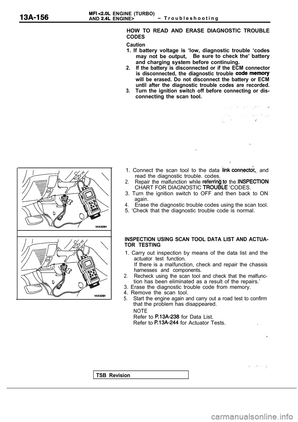
HOW TO READ AND ERASE DIAGNOSTIC TROUBLE
CODES
Caution
1. If battery voltage is ‘low, diagnostic trouble ‘ codes
may not be output, Be sure to check the’ battery
and charging system before continuing.
2.If the battery is disconnected or if the ECM connec tor
is disconnected, the diagnostic trouble
will be erased. Do not disconnect the battery or EC M
until after the diagnostic trouble codes are record ed.
3.Turn the ignition switch off before connecting or d is-
connecting the scan tool.
,
1. Connect the scan tool to the data and
read the diagnostic trouble. codes.
2.Repair the malfunction while the
CHART FOR DIAGNOSTIC ‘CODES.
3. Turn the ignition switch to OFF and then back to ON
again.
4.Erase the diagnostic trouble codes using the scan tool.
5. ‘Check that the diagnostic trouble code is norma l.
INSPECTION USING SCAN TOOL DATA LIST AND ACTUA-
TOR TESTING
1. Carry out inspection by means of the data list a nd the
actuator test function.
If there is a malfunction, check and repair the chassis
harnesses and components.
2.Recheck using the scan tool and check that the malf unc-
tion has been eliminated as a result of the repairs.’
3. Erase the diagnostic trouble code from memory.
4. Remove the scan tool.
5.Start the engine again and carry out a road test to confirm
that the problem has disappeared.
NOTE
Refer to for Data List.
Refer to
for Actuator Tests..
TSB Revision
Page 571 of 2103
![MITSUBISHI SPYDER 1990 Service Repair Manual ENGINE (TURBO)
AND ENGINE> Troubleshooting
Code No. Power Steering Pressure Sensor CircuitProbable cause
[Comment] Power pressure switch Backgroundl Open or shorted power steering MITSUBISHI SPYDER 1990 Service Repair Manual ENGINE (TURBO)
AND ENGINE> Troubleshooting
Code No. Power Steering Pressure Sensor CircuitProbable cause
[Comment] Power pressure switch Backgroundl Open or shorted power steering](/img/19/57345/w960_57345-570.png)
ENGINE (TURBO)
AND ENGINE> Troubleshooting
Code No. Power Steering Pressure Sensor CircuitProbable cause
[Comment] Power pressure switch Backgroundl Open or shorted power steering pressurelWhen the steering wheel is kept in the position during driving, the power
s w i t c h or steering pressure switch will be momentarily turned off. E n g i n e c o n t r o l f a i l e d ’lThe enginecontrol module checks whetherthe powerste ering pressure switch momentarilyturns off during driving.
Check Area Engine coolant temperature is or higher.
l Driving and stopping ‘2 are repeated times or more.“1: Engine speed is 2,500 or higher, volumetric efficiency is 55% or higher, and this
condition continues for 2 seconds or more.
l 2: Engine speed is 600 or lower.
Judgement Criterial Power steering pressure switch stays on without cha nging.
NGCheck the power steering press On-vehicle Service) Replace
lDisconnect the connector and measure at the harness side.
NG
between ECM and power pressure switch
NG
the ECM. Replace the ECM.
Code No. Transmission Range Sensor Circuit
Malfunction (RPNDL Input)
[Comment]
Background
lWhen a malfunction of the park/neutral position swi tch is detected, the transaxle control
module outputs amalfunction signal to the engine control module.
Check Area, Judgement Criteria l
control module.
Check the TCM. (Refer to GROUP Troubleshooting.)
Repair
Repair
cause
l Park/neutral position switch failedlOpen or shorted park/neutral position switchcircuit, or loose connector.
l Engine control module failed.
Code No. Turbocharger Waste Gate Actuator
Malfunction
(Turbo)> Probable cause
l
Turbocharger waste gateactuator failed.
l Charging pressure control system failed.
l Engine control module failed.[Comment]
Background
lThe engine control module checks that the engine is not overcharged by always monitoringintake air volume.lThe engine control module protects the engine by shutting off fuel when an overcharged
condition is detected.
Check Area
Engine coolant temperature is higher than
Judgement Criterial Volumetric efficiency has continued to be not lower than 200% for 1.5 sec.
Check the turbocharger supercharging. (Refer to GROUP 15
On-vehicle Service.)
TSB Revision