wheel bolts MITSUBISHI SPYDER 1990 Service Repair Manual
[x] Cancel search | Manufacturer: MITSUBISHI, Model Year: 1990, Model line: SPYDER, Model: MITSUBISHI SPYDER 1990Pages: 2103, PDF Size: 68.98 MB
Page 5 of 2103
GENERAL How to Use This
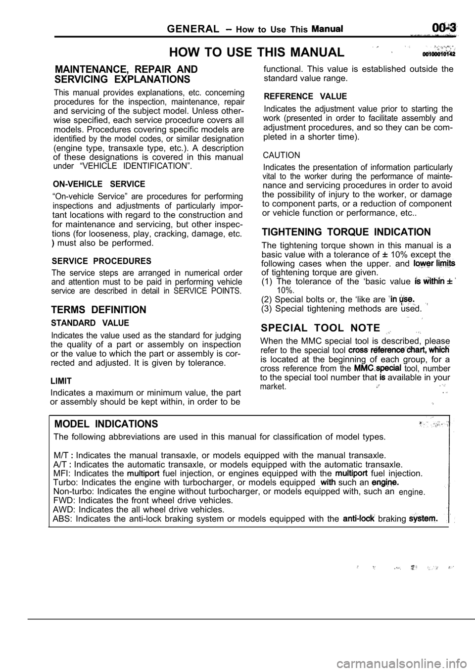
HOW TO USE THIS MANUAL
MAINTENANCE, REPAIR AND
SERVICING EXPLANATIONS
This manual provides explanations, etc. concerning procedures for the inspection, maintenance, repair
and servicing of the subject model. Unless other-
wise specified, each service procedure covers all
models. Procedures covering specific models are
identified by the model codes, or similar designati on
(engine type, transaxle type, etc.). A description
of these designations is covered in this manual
under “VEHICLE IDENTIFICATION”.
ON-VEHICLE SERVICE
“On-vehicle Service” are procedures for performing
inspections and adjustments of particularly impor-
tant locations with regard to the construction and
for maintenance and servicing, but other inspec-
tions (for looseness, play, cracking, damage, etc.
must also be performed.
SERVICE PROCEDURES
The service steps are arranged in numerical order
and attention must to be paid in performing vehicle
service are described in detail in SERVICE POINTS.
TERMS DEFINITION
STANDARD VALUE
Indicates the value used as the standard for judgin g
the quality of a part or assembly on inspection
or the value to which the part or assembly is cor-
rected and adjusted. It is given by tolerance.
LIMIT
Indicates a maximum or minimum value, the part
or assembly should be kept within, in order to be functional. This value is established outside the
standard value range.
REFERENCE VALUE
Indicates the adjustment value prior to starting th e
work (presented in order to facilitate assembly and
adjustment procedures, and so they can be com-
pleted in a shorter time).
CAUTION
Indicates the presentation of information particula rly
vital to the worker during the performance of maint e-
nance and servicing procedures in order to avoid
the possibility of injury to the worker, or damage
to component parts, or a reduction of component
or vehicle function or performance, etc..
TIGHTENING TORQUE INDICATION
The tightening torque shown in this manual is a
basic value with a tolerance of
10% except the
following cases when the upper. and
of tightening torque are given. (1) The tolerance of the ‘basic value
10%.
(2) Special bolts or, the ‘like are
(3) Special tightening methods are used.
SPECIAL TOOL NOTE
When the MMC special tool is described, please
refer to the special tool
is located at the beginning of each group, for a
cross reference from the tool, number
to the special tool number that available in your
market..
MODEL INDICATIONS
The following abbreviations are used in this manual for classification of model types.
M/T
Indicates the manual transaxle, or models equipped with the manual transaxle.
A/T
Indicates the automatic transaxle, or models equip ped with the automatic transaxle.
MFI: Indicates the
fuel injection, or engines equipped with the fuel injection.
Turbo: Indicates the engine with turbocharger, or m odels equipped
such an
Non-turbo: Indicates the engine without turbocharger, or models equipped with, such anengine.
FWD: Indicates the front wheel drive vehicles.
AWD: Indicates the all wheel drive vehicles.
ABS: Indicates the anti-lock braking system or mode ls equipped with the
braking
Page 58 of 2103
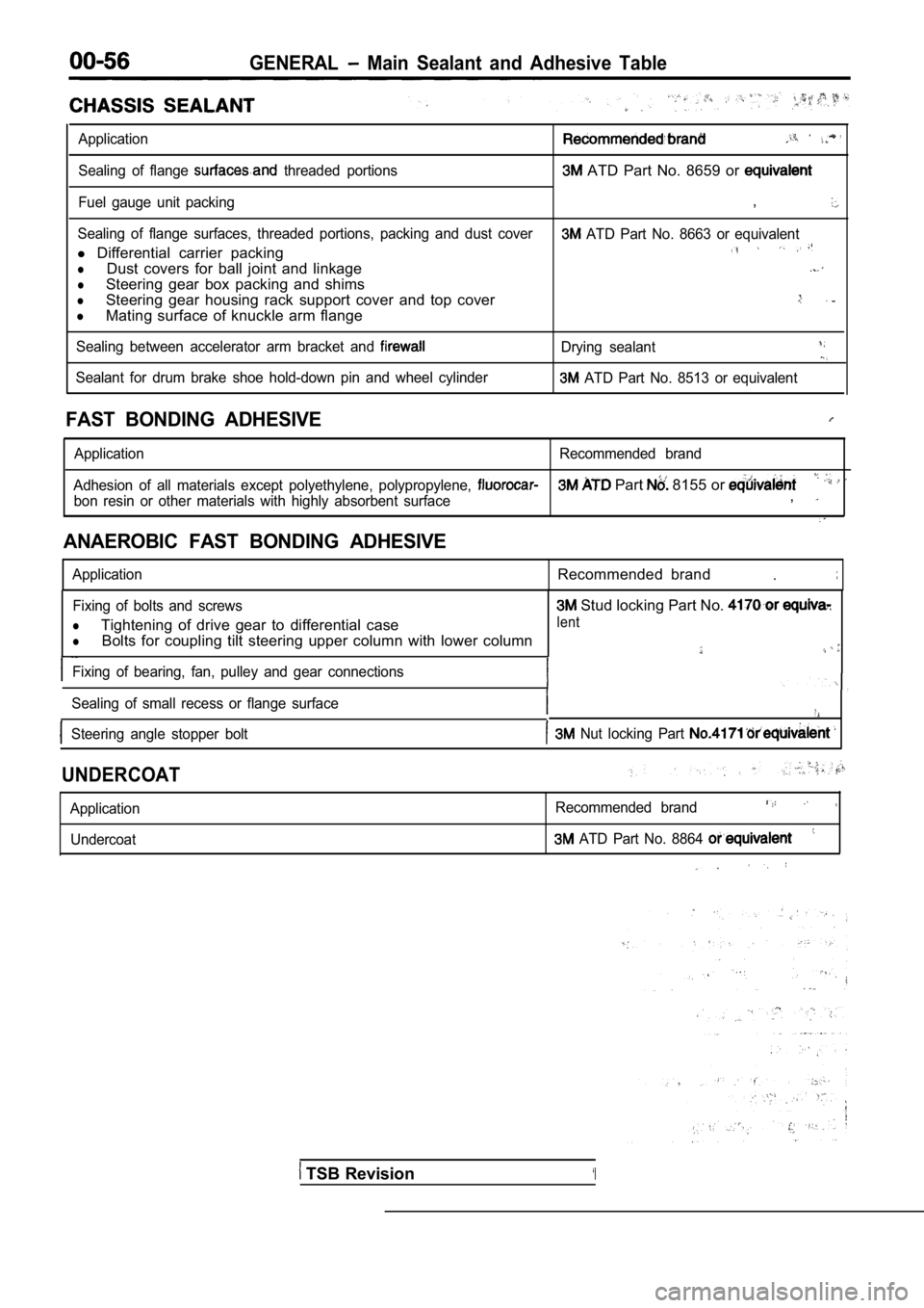
GENERAL Main Sealant and Adhesive Table
Application
Sealing of flange threaded portions ATD Part No. 8659 or
Fuel gauge unit packing,
Sealing of flange surfaces, threaded portions, packing and dust cover ATD Part No. 8663 or equivalent
l Differential carrier packing
lDust covers for ball joint and linkage
lSteering gear box packing and shims
lSteering gear housing rack support cover and top co ver
lMating surface of knuckle arm flange
Sealing between accelerator arm bracket and Drying sealant
Sealant for drum brake shoe hold-down pin and wheel cylinder ATD Part No. 8513 or equivalent
FAST BONDING ADHESIVE
Application Recommended brand
Adhesion of all materials except polyethylene, poly propylene,
Part 8155 or
bon resin or other materials with highly absorbent surface,
ANAEROBIC FAST BONDING ADHESIVE
ApplicationRecommended brand.
Fixing of bolts and screws
lTightening of drive gear to differential case
lBolts for coupling tilt steering upper column with lower column
Fixing of bearing, fan, pulley and gear connections
Sealing of small recess or flange surface
Steering angle stopper bolt Nut locking Part
Stud locking Part No.
lent
UNDERCOAT
Application Undercoat Recommended brand
ATD Part No. 8864
TSB Revision‘I
Page 90 of 2103
11ENGINE Crankshaft pear Oil
,
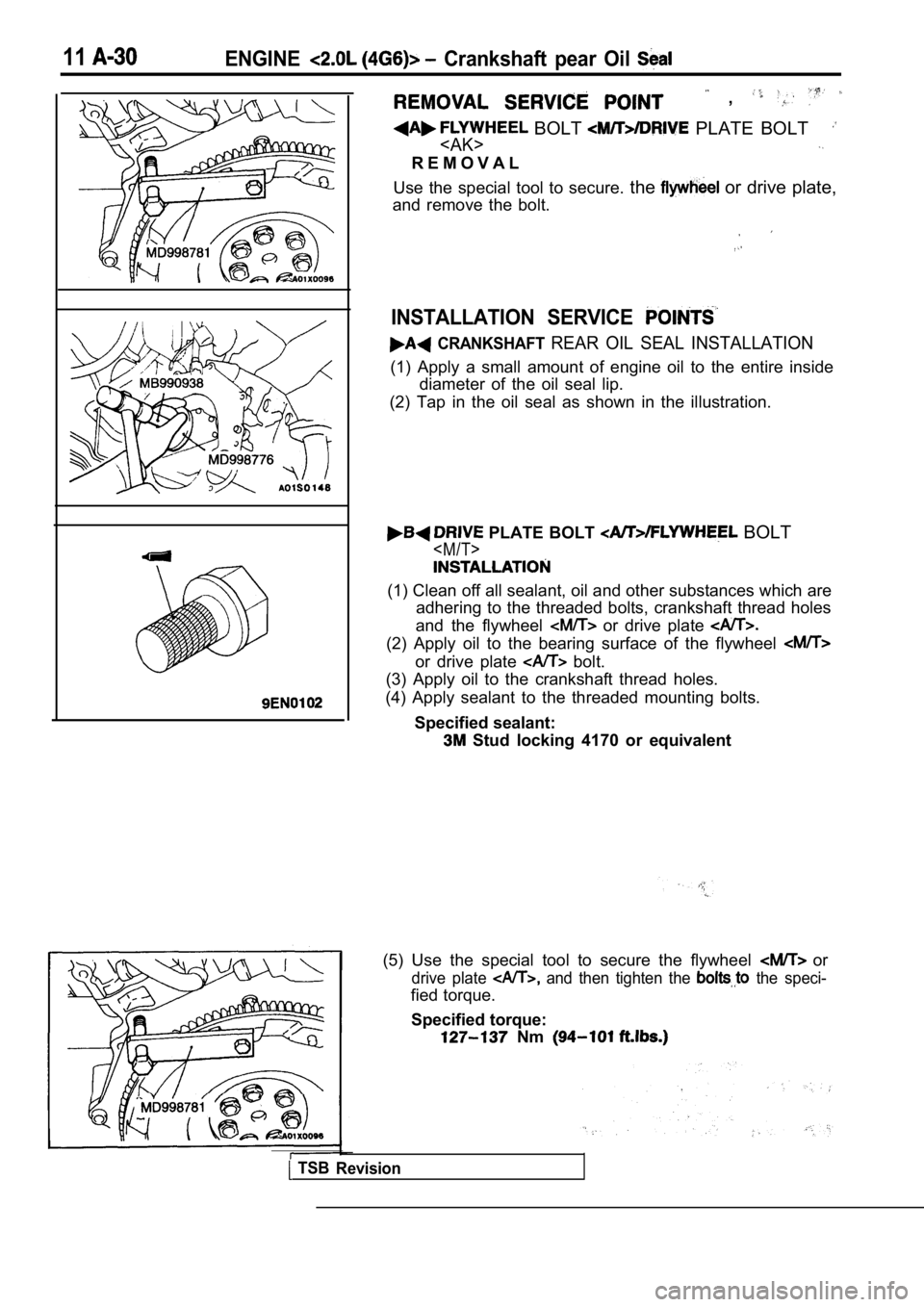
BOLT PLATE BOLT
R E M O V A L
Use the special tool to secure. the
or drive plate,
and remove the bolt.
INSTALLATION SERVICE
CRANKSHAFT REAR OIL SEAL INSTALLATION
(1) Apply a small amount of engine oil to the entir e inside
diameter of the oil seal lip.
(2) Tap in the oil seal as shown in the illustratio n.
PLATE BOLT BOLT
(1) Clean off all sealant, oil and other substances which are
adhering to the threaded bolts, crankshaft thread h oles
and the flywheel
or drive plate
(2) Apply oil to the bearing surface of the flywhee l
or drive plate bolt.
(3) Apply oil to the crankshaft thread holes.
(4) Apply sealant to the threaded mounting bolts.
Specified sealant:
Stud locking 4170 or equivalent
TSB Revision
(5) Use the special tool to secure the flywheel or
drive plate and then tighten the the speci-
fied torque.
Specified torque:
Nm
Page 296 of 2103
INSTALLATION SERVICE POINTS
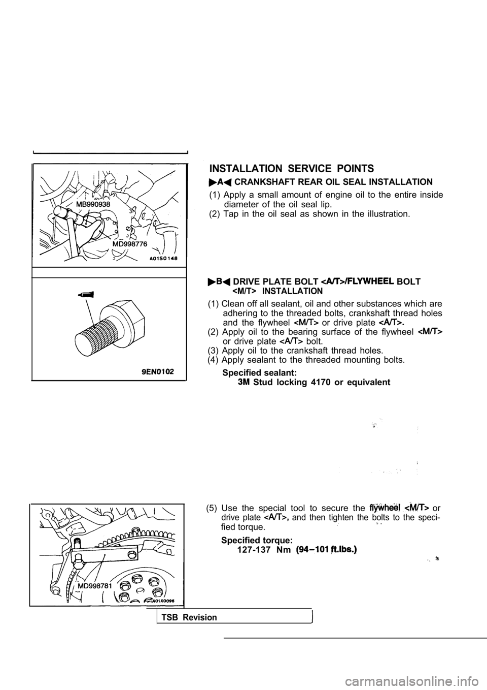
CRANKSHAFT REAR OIL SEAL INSTALLATION
(1) Apply a small amount of engine oil to the entir e inside
diameter of the oil seal lip.
(2) Tap in the oil seal as shown in the illustratio n.
DRIVE PLATE BOLT BOLT
(1) Clean off all sealant, oil and other substances which are
adhering to the threaded bolts, crankshaft thread h oles
and the flywheel
or drive plate
(2) Apply oil to the bearing surface of the flywhee l
or drive plate bolt.
(3) Apply oil to the crankshaft thread holes.
(4) Apply sealant to the threaded mounting bolts.
Specified sealant:
Stud locking 4170 or equivalent
(5) Use the special tool to secure the
or
drive plate and then tighten the bolts to the speci-
fied torque. .
Specified torque: 127-137 Nm
TSB Revision
Page 369 of 2103
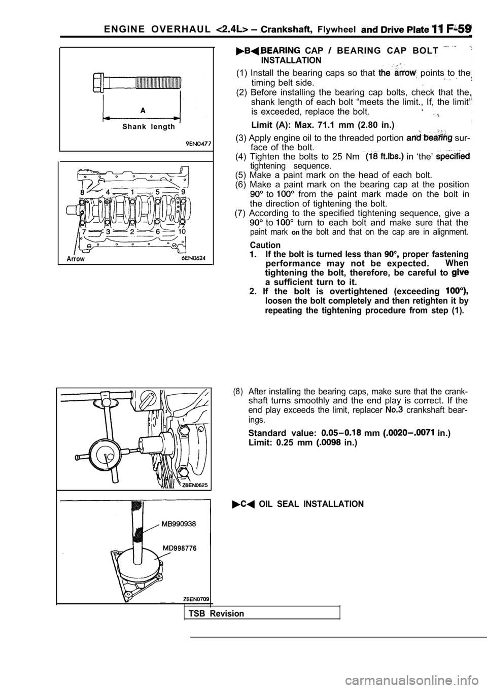
E N G I N E O V E R H A U L Flywheel
S h a n k l e n g t h
Arrow
CAP B E A R I N G C A P B O L T
INSTALLATION
(1) Install the bearing caps so that points to the
timing belt side.
(2) Before installing the bearing cap bolts, check that the,
shank length of each bolt “meets the limit., If, th e limit’
is exceeded, replace the bolt.
Limit (A): Max. 71.1 mm (2.80 in.)
(3) Apply engine oil to the threaded portion
sur-
face of the bolt.
(4) Tighten the bolts to 25 Nm
in ‘the’
tightening sequence.
(5) Make a paint mark on the head of each bolt.
(6) Make a paint mark on the bearing cap at the pos ition
to from the paint mark made on the bolt in
the direction of tightening the bolt.
(7) According to the specified tightening sequence, give a
to turn to each bolt and make sure that the
paint mark onthe bolt and that on the cap are in alignment.
Caution
If the bolt is turned less than proper fastening
performance may not be expected.When
tightening the bolt, therefore, be careful to
a sufficient turn to it.
2. If the bolt is overtightened (exceeding
loosen the bolt completely and then retighten it by
repeating the tightening procedure from step (1).
(8)After installing the bearing caps, make sure that t he crank-
shaft turns smoothly and the end play is correct. I f the
end play exceeds the limit, replacer crankshaft bear-
ings.
Standard value: mm in.)
Limit: 0.25 mm
in.)
OIL SEAL INSTALLATION
998776
TSB Revision
Page 371 of 2103
ENGINE OVERHAUL Crankshaft, Flywheel and, . .
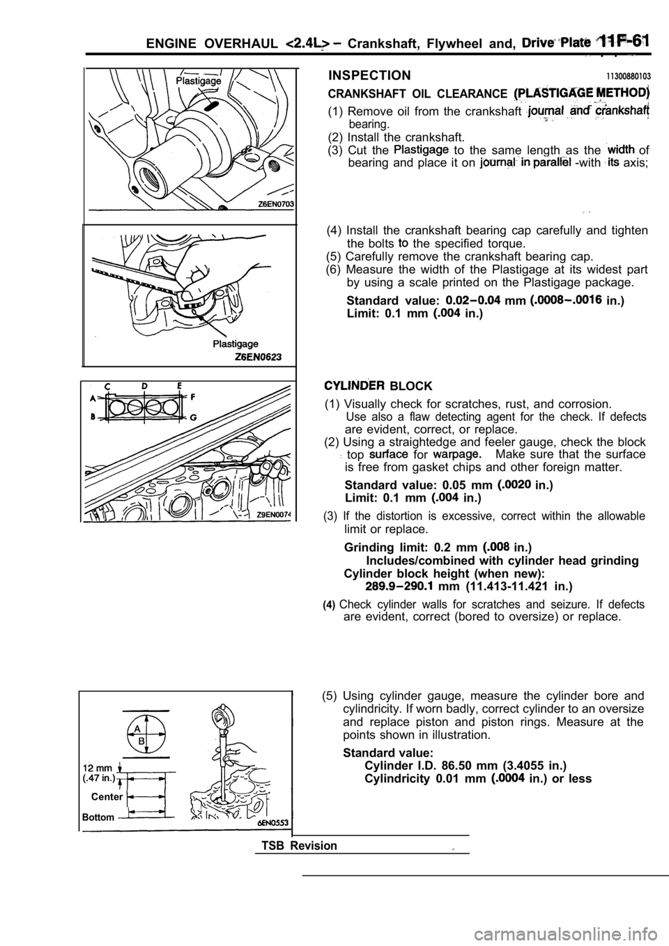
INSPECTION11300880103
CRANKSHAFT OIL CLEARANCE
(1) Remove oil from the crankshaft
bearing.
(2) Install the crankshaft.
(3) Cut the
to the same length as the of
bearing and place it on
-with axis;
(4) Install the crankshaft bearing cap carefully an d tighten
the bolts
the specified torque.
(5) Carefully remove the crankshaft bearing cap.
(6) Measure the width of the Plastigage at its wide st part
by using a scale printed on the Plastigage package.
Standard value:
mm in.)
Limit: 0.1 mm
in.)
BLOCK
(1) Visually check for scratches, rust, and corrosi on.
Use also a flaw detecting agent for the check. If d efects
are evident, correct, or replace.
(2) Using a straightedge and feeler gauge, check th e block
top for Make sure that the surface
is free from gasket chips and other foreign matter.
Standard value: 0.05 mm
in.)
Limit: 0.1 mm
in.)
(3) If the distortion is excessive, correct within the allowable
limit or replace.
Grinding limit: 0.2 mm
in.)
Includes/combined with cylinder head grinding
Cylinder block height (when new):
mm (11.413-11.421 in.)
(4)Check cylinder walls for scratches and seizure. If defects
are evident, correct (bored to oversize) or replace.
Center
Bottom
TSB Revision
(5) Using cylinder gauge, measure the cylinder bore and
cylindricity. If worn badly, correct cylinder to an oversize
and replace piston and piston rings. Measure at the
points shown in illustration.
Standard value: Cylinder I.D. 86.50 mm (3.4055 in.)
Cylindricity 0.01 mm
in.) or less
Page 734 of 2103
INTAKE AND EXHAUST Exhaust Manifold ENGINE (Turbo)>
Identification holeExhaust
manifold
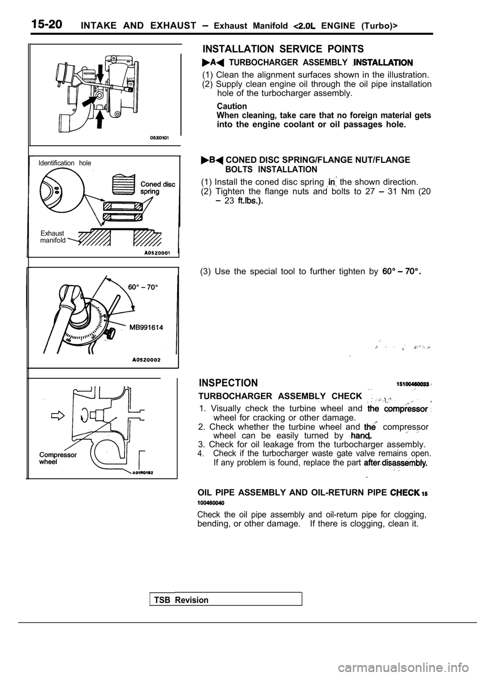
INSTALLATION SERVICE POINTS
TURBOCHARGER ASSEMBLY
(1) Clean the alignment surfaces shown in the illus tration.
(2) Supply clean engine oil through the oil pipe in stallation
hole of the turbocharger assembly.
Caution
When cleaning, take care that no foreign material g ets
into the engine coolant or oil passages hole.
CONED DISC SPRING/FLANGE NUT/FLANGE
BOLTS INSTALLATION
(1) Install the coned disc spring the shown direction.
(2) Tighten the flange nuts and bolts to 27
31 Nm (20
23
(3) Use the special tool to further tighten by
INSPECTION
TURBOCHARGER ASSEMBLY CHECK . .
1. Visually check the turbine wheel and
wheel for cracking or other damage.
2. Check whether the turbine wheel and
compressor
wheel can be easily turned by
3. Check for oil leakage from the turbocharger asse mbly.
4.Check if the turbocharger waste gate valve remains open.
If any problem is found, replace the part
.
OIL PIPE ASSEMBLY AND OIL-RETURN PIPE
Check the oil pipe assembly and oil-return pipe for clogging,
bending, or other damage. If there is clogging, clea n it.
TSB Revision
Page 1509 of 2103
I
8990767
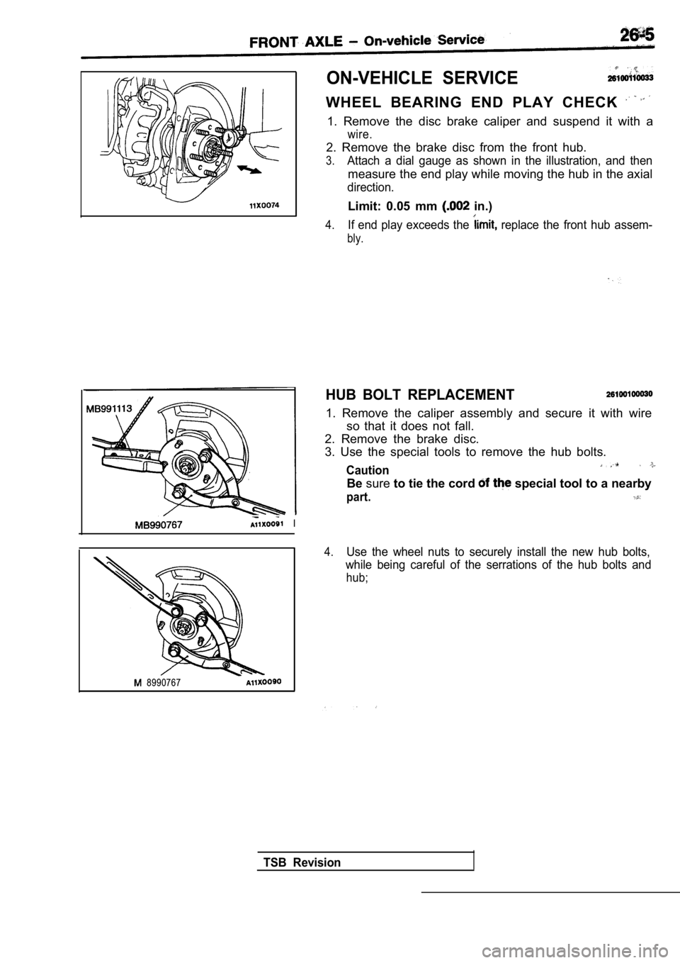
ON-VEHICLE SERVICE
WHEEL BEARING END PLAY CHECK
1. Remove the disc brake caliper and suspend it with a
wire.
2. Remove the brake disc from the front hub.
3.Attach a dial gauge as shown in the illustration, and then
measure the end play while moving the hub in the ax ial
direction.
Limit: 0.05 mm in.)
4.If end play exceeds the replace the front hub assem-
bly.
HUB BOLT REPLACEMENT
1. Remove the caliper assembly and secure it with w ire
so that it does not fall.
2. Remove the brake disc.
3. Use the special tools to remove the hub bolts.
Caution
Be sure to tie the cord special tool to a nearby
part.
4.Use the wheel nuts to securely install the new hub bolts,
while being careful of the serrations of the hub bo lts and
hub;
TSB Revision
Page 1511 of 2103
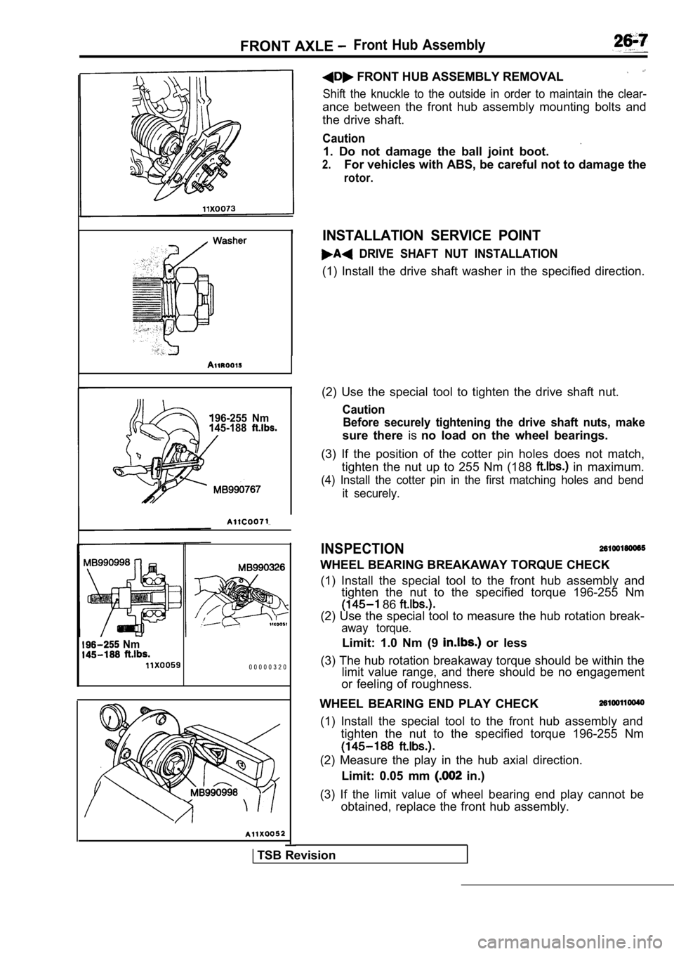
FRONT AXLE Front Hub Assembly
196-255 Nm
145-188
I(2) Use the special tool to tighten the drive shaft nut.
Caution
Before securely tightening the drive shaft nuts, ma ke
sure there isno load on the wheel bearings.
(3) If the position of the cotter pin holes does no t match,
tighten the nut up to 255 Nm (188
in maximum.
(4) Install the cotter pin in the first matching ho les and bend
it securely.
INSPECTION
WHEEL BEARING BREAKAWAY TORQUE CHECK
(1) Install the special tool to the front hub assem bly and
tighten the nut to the specified torque 196-255 Nm
86
(2) Use the special tool to measure the hub rotatio n break-
away torque.
Limit: 1.0 Nm (9 or less
(3) The hub rotation breakaway torque should be wit hin the
limit value range, and there should be no engagemen t
or feeling of roughness. Nm
0 0 0 0 0 3 2 0
FRONT HUB ASSEMBLY REMOVAL
Shift the knuckle to the outside in order to mainta in the clear-
ance between the front hub assembly mounting bolts and
the drive shaft.
Caution
1. Do not damage the ball joint boot.
2.For vehicles with ABS, be careful not to damage the
rotor.
INSTALLATION SERVICE POINT
DRIVE SHAFT NUT INSTALLATION
(1) Install the drive shaft washer in the specified direction.
WHEEL BEARING END PLAY CHECK
(1) Install the special tool to the front hub assem bly and
tighten the nut to the specified torque 196-255 Nm
(2) Measure the play in the hub axial direction.
Limit: 0.05 mm
in.)
(3) If the limit value of wheel bearing end play ca nnot be
obtained, replace the front hub assembly.
TSB Revision
Page 1538 of 2103
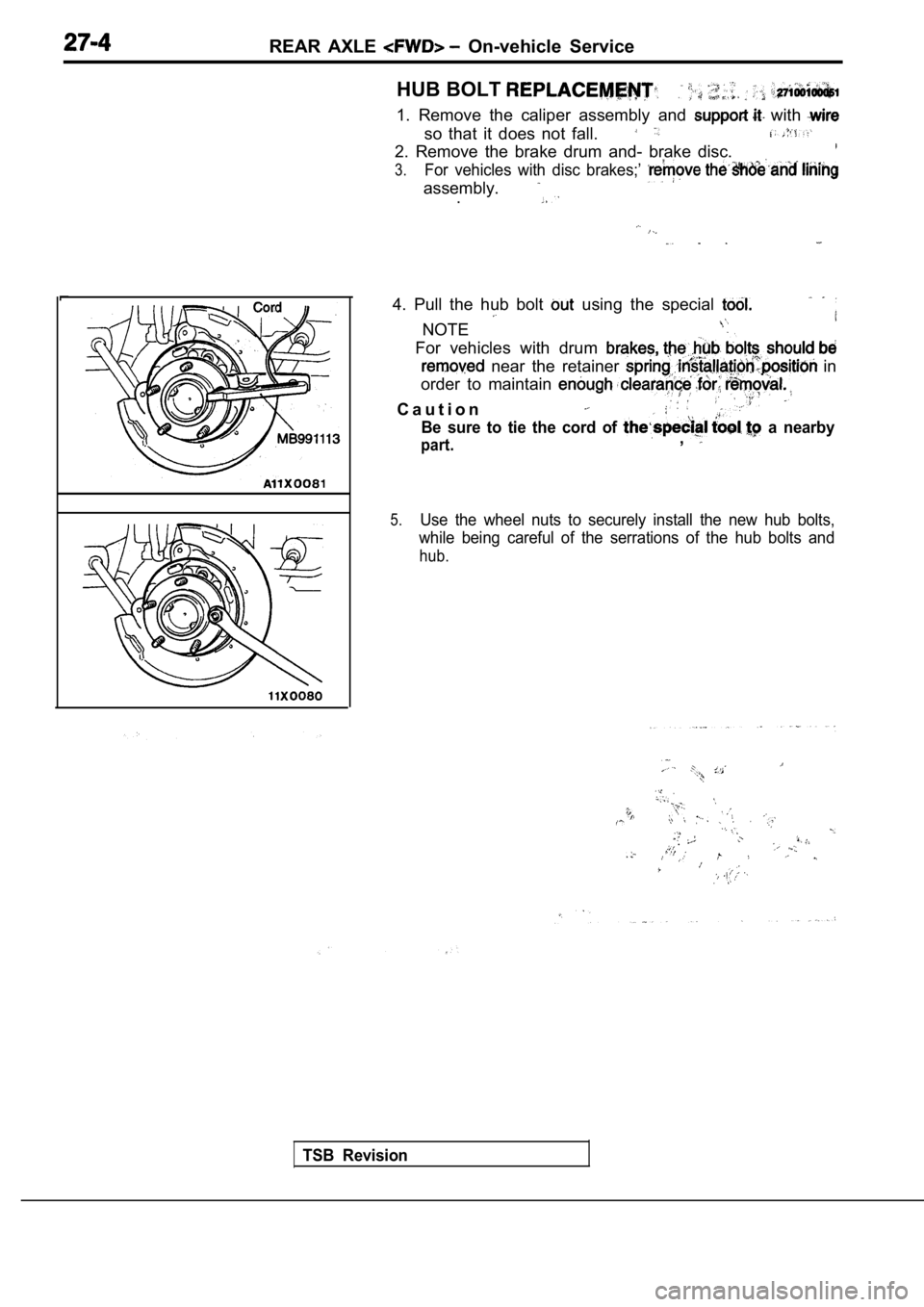
REAR AXLE On-vehicle Service
HUB BOLT
1. Remove the caliper assembly and with
so that it does not fall.
2. Remove the brake drum and- brake disc.
3.For vehicles with disc brakes;’
assembly..
4. Pull the hub bolt using the special
NOTE
For vehicles with drum
near the retainer in
order to maintain
C a u t i o n
Be sure to tie the cord of a nearby
part.,
5.Use the wheel nuts to securely install the new hub bolts,
while being careful of the serrations of the hub bo lts and
hub.
TSB Revision
.
,
,
,