oil reset MITSUBISHI SPYDER 1990 Service Repair Manual
[x] Cancel search | Manufacturer: MITSUBISHI, Model Year: 1990, Model line: SPYDER, Model: MITSUBISHI SPYDER 1990Pages: 2103, PDF Size: 68.98 MB
Page 123 of 2103
![MITSUBISHI SPYDER 1990 Service Repair Manual ENGINE OVERHAUL Belt
Phillips screwdriver
BOLT
O I L S P R O C K E T
(1) a Phillips screwdriver [shank diameter 8 mm
in.) shaft] through the plug hole on the the
cylinde MITSUBISHI SPYDER 1990 Service Repair Manual ENGINE OVERHAUL Belt
Phillips screwdriver
BOLT
O I L S P R O C K E T
(1) a Phillips screwdriver [shank diameter 8 mm
in.) shaft] through the plug hole on the the
cylinde](/img/19/57345/w960_57345-122.png)
ENGINE OVERHAUL Belt
Phillips screwdriver
BOLT
O I L S P R O C K E T
(1) a Phillips screwdriver [shank diameter 8 mm
in.) shaft] through the plug hole on the the
cylinder block to block the left counterbalance sha ft.
(2)
the oil pump sprocket. .
(3) Apply a proper amount of engine oil-to the bearing
of the nuts.
(4) Tighten the nuts to the specified‘ torque.
AUTO TENSIONER INSTALLATION
(1) If the auto tensioner rod is in its fully exten ded position,
reset it as follows.
(2) Clamp the auto-tensioner in the vise
jaws.
(3) Push in the rod little by little with the vise the
hole A in the rod is aligned with the hole in the
(4) a wire mm in.) diameter] into the
(5) Unclamp the auto tensioner from the vise.
.
,
the auto tensioner to front case and tighten.
the specified torque.
Caution
Leave the wire installed the
,
. .
,
TSB Revision
Page 327 of 2103

ENGINE OVERHAUL Timing Belt
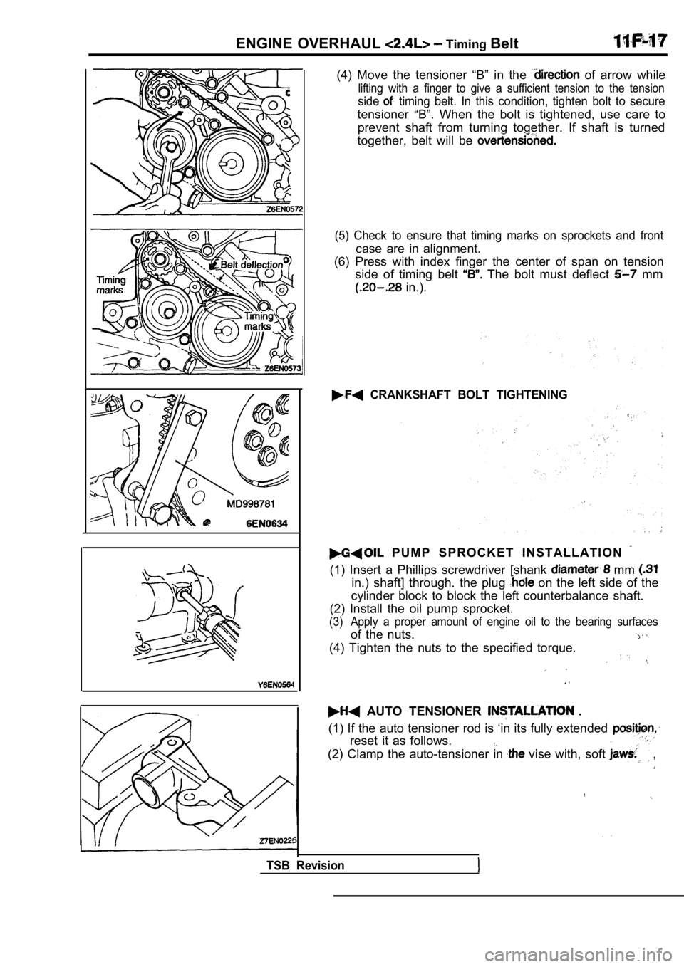
(4) Move the tensioner “B” in the of arrow while
lifting with a finger to give a sufficient tension to the tension
side timing belt. In this condition, tighten bolt to secure
tensioner “B”. When the bolt is tightened, use care to
prevent shaft from turning together. If shaft is tu rned
together, belt will be
(5) Check to ensure that timing marks on sprockets and front
case are in alignment.
(6) Press with index finger the center of span on t ension
side of timing belt
The bolt must deflect mm
in.).
CRANKSHAFT BOLT TIGHTENING
P U M P S P R O C K E T I N S T A L L A T I O N
(1) Insert a Phillips screwdriver [shank mm
in.) shaft] through. the plug on the left side of the
cylinder block to block the left counterbalance sha ft.
(2) Install the oil pump sprocket.
(3) Apply a proper amount of engine oil to the beari ng surfaces
of the nuts.
(4) Tighten the nuts to the specified torque.
AUTO TENSIONER .
(1) If the auto tensioner rod is ‘in its fully exte nded
reset it as follows.
(2) Clamp the auto-tensioner in vise with, soft ,
TSB Revision
Page 469 of 2103
![MITSUBISHI SPYDER 1990 Service Repair Manual ENGINE (NON-TURBO)> Troubleshooting
INSPECTION PROCEDURE 8
Unstable idle (Rough idle, hunting)Probable cause
[Comment] Malfunction of the ignition system
In cases such as the abo MITSUBISHI SPYDER 1990 Service Repair Manual ENGINE (NON-TURBO)> Troubleshooting
INSPECTION PROCEDURE 8
Unstable idle (Rough idle, hunting)Probable cause
[Comment] Malfunction of the ignition system
In cases such as the abo](/img/19/57345/w960_57345-468.png)
ENGINE (NON-TURBO)> Troubleshooting
INSPECTION PROCEDURE 8
Unstable idle (Rough idle, hunting)Probable cause
[Comment] Malfunction of the ignition system
In cases such as the above, the cause is probably t hat the ignition system,l Malfunction of air-fuel ratio system
idle air control motor or compression pressure is d efective.
l Malfunction of the system
Because the range of possible causes is broad, insp ection is narrowed down to simple items.
l Malfunction of the evaporative emission
purge solenoid system
l Malfunction of the EGR system
l Poor compression
l Drawing air into exhaust system
W ere the battery terminals disconnected recently?
SCAN TOOL DTC
Are diagnostic trouble codes output
NO Refer to
INSPECTION CHART FOR DIAGNOSTICTROUBLE CODES.
YES
Inspection when hunting occurs.
(Refer to INSPECTION PROCEDURE 31.)
SCANTOOL Actuator test
07 motor (Refer to
OK
NG Check the idle air control motor (Refer to P. INSPECTION PROCEDURE FOR DIAGNOSTIC TROUBLE CODE
SCAN TOOL Specialfunction
“Reset
I
Check trouble symptoms.
OK
Scan tool: Inspection when idle speed is unstable. (Refer
to INSPECTION PROCEDURE 32.)
OK
Check the injector control circuit: (Carry out pro cedures 19, 20, 21, in “INSPECTION PROCEDURE
FOR DIAGNOSTIC TROUBLE CODES”.)
Check the following items. l Check the ignition coil, spark plugs, spark plug ca bles.
l Check the purge control system.
l Check the EGR svstem.
l Check the compression pressure.
l Check if foreign materials (water, alcohol, etc.) g ot into fuel.
TSB Revision
Page 471 of 2103
![MITSUBISHI SPYDER 1990 Service Repair Manual ENGINE,
INSPECTION PROCEDURE 11When the engine is cold, it stalls at idle. (Die ou t)
[Comment]lMalfunction of the idle air control
In such cases as the above, the cause is pro MITSUBISHI SPYDER 1990 Service Repair Manual ENGINE,
INSPECTION PROCEDURE 11When the engine is cold, it stalls at idle. (Die ou t)
[Comment]lMalfunction of the idle air control
In such cases as the above, the cause is pro](/img/19/57345/w960_57345-470.png)
ENGINE,
INSPECTION PROCEDURE 11When the engine is cold, it stalls at idle. (Die ou t)
[Comment]lMalfunction of the idle air control
In such cases as the above, the cause is probably t hat the air/fuel mixture is inappropriate when l Malfunction of the fhroffle body the engine is cold, or that the intake air volume i s insufficient..l Malfunction of the injector System l Malfunction: system
W ere the battery terminals disconnected recently?
NO
SCAN TOOL DTC
.After warming-up, let the engine run at idling for 10 minutes.I
,
Are diagnostic trouble codes output?TROUBLE CODES
N OI -.: .
Does the engine stall right after the accelerator p
edal is
Check the throffle body minimum air (Refer to released
NO . . . N O Check for unstable idle (Rough hunting)Is engine-idling stable after the warming-up?
YES(Refer to INSPECTION 8.)
SCAN TOOL Actuator test
07 motor (Refer to
OK NG
Check the idle air control motor circuit. (Refer t
o INSPECTION PROCEDURE FOR TROUBLE CODE
SCAN TOOL Special function
“Reset
Check trouble symptoms.
NG
OK
.
Check the injector control circuit. Carry procedures 19, in “INSPECTION PROCEDUREFOR DIAGNOSTIC TROUBLE
Check the fuel pressure. (Refer to
Check the following items.
l Check the ignition coil, spark plugs, spark plug ca bles.
l Check the compression pressure.
l Check the engine oil viscosity.
TSB Revision
Page 472 of 2103
![MITSUBISHI SPYDER 1990 Service Repair Manual E N G I N E
INSPECTION PROCEDURE 12 , .
. .
When the engine is hot, it stalls at idle. (Die out )
[Comment]l Malfunction of the ignition In cases such as the above, the caus MITSUBISHI SPYDER 1990 Service Repair Manual E N G I N E
INSPECTION PROCEDURE 12 , .
. .
When the engine is hot, it stalls at idle. (Die out )
[Comment]l Malfunction of the ignition In cases such as the above, the caus](/img/19/57345/w960_57345-471.png)
E N G I N E
INSPECTION PROCEDURE 12 , .
. .
When the engine is hot, it stalls at idle. (Die out )
[Comment]l Malfunction of the ignition In cases such as the above, the cause is probably t hat ignition system, mixture, idle l
air control motor or compression pressure is defect ive.Malfunction control M a l f u n c t i o n o f t h e s y s t e m In addition, if the engine stalls, the cause
mayalso be a defective connector contact.l into intake system
l Improper connector contact
W ere the battery terminals disconnected recently
NO
YES After warming-up, let the engine run at idling for 10 minutes.
SCAN TOOL DTC
Are diagnostic trouble codes output?
NO
SCAN TOOL Actuator test
07 motor. (Refer to
OK YES
N G
Refer to INSPECTION CHART FOR DIAGNOSTICTROUBLE CODES.
Checktheidleaircontrolmotorcircuit. INSPECTIONPROCEDURE FOR DIAGNOSTIC TROUBLE CODE
SCAN TOOL Special function
“Reset
Check trouble symptoms.
NG
Check the injector for operation sound.
(Refer to Check the injector control circuit. Carry out proc edures 20, in “INSPECTION PROCEDURE
FOR DIAGNOSTIC TROUBLE CODES”.
Does the engine stall right
released
NO.
Does the engine stall easily again
YES
Scan tool: Inspection when engine stalls when the e ngine
is warm and idling (Refer to INSPECTIONPROCEDURE 33.)
OK
Check the throttle body minimum air flow (Refer to
While carrying out an intermittent malfunction simulation test (Refer
to GROUP 00 How to Cope with Intermittent Malfunctions), check
for sudden changes in the signals shown below.
l Crankshaft position sensor and
l MAP sensor signal Fuel pump signall Injector drive signal l power supply voltage
Check the following items.
l
Check the ignition coil, spark plugs, spark plug ca bles.
l Clean the injectors.
l Check the compression pressure.
l Check if foreign materials (water, alcohol, etc.) g ot into fuel.
INSPECTION PROCEDURE 13
The engine stalls when accelerating. (Pass out) Probable cause
[Comment]l
Injectors failedIn cases such as the above, the cause is probably m isfiring due to a weak spark, or an inappropriatelMalfunction of the ignition system
air/fuel mixture when the accelerator is depressed.
YESRefer to INSPECTION CHART FORDIAGNOSTIC
Arediagnostic trouble codes outputTROUBLE CODES.
NO
Check the following items.
l Check the ignition coil, spark plugs, spark plug ca bles.
l Clogged injectors
Page 474 of 2103
![MITSUBISHI SPYDER 1990 Service Repair Manual E N G I N E
INSPECTION PROCEDURE 16 . ,
Acceleration shock ,
[Comment] Malfunction of the ignition systemIn cases such as the above, the cause is probably that there is an ignition leak ac MITSUBISHI SPYDER 1990 Service Repair Manual E N G I N E
INSPECTION PROCEDURE 16 . ,
Acceleration shock ,
[Comment] Malfunction of the ignition systemIn cases such as the above, the cause is probably that there is an ignition leak ac](/img/19/57345/w960_57345-473.png)
E N G I N E
INSPECTION PROCEDURE 16 . ,
Acceleration shock ,
[Comment] Malfunction of the ignition systemIn cases such as the above, the cause is probably that there is an ignition leak accompanyinglthe increase in the spark plug demand voltage durin g acceleration.Improper control of reduction stiifting.
Are diagnostic trouble codes output
NO YES
Refer to INSPECTION CHART D I A G N O S T I CTROUBLE CODES.
Check the following items.
l
Check the ignition coil, spark plugs, spark plug ca bles.
l Check for occurrence of ignition leak.
l Check the torque reduction link (wire) between the PCM and TCM.
INSPECTION PROCEDURE 17
Deceleration shock Probable cause
[Comment]Malfunction of the system is suspected.l Malfunction of ‘system
III
Are diagnostic trouble codes output
NO
YESR e f e r t o C H A R T F O R TROUBLE CODES.
SCAN TOOL Actuator test
07 motor. (Refer to PROCEDURE FOR DIAGNOSTIC TROUBLE CODES
SCAN TOOL Special function“Reset
Check trouble I
N G
TSB Revision
Check the throttle body minimum air flow.
(Refer to
SCAN TOOL SENS
07 Throttle position (Refer to NGl Check the throttle position sensor
(Refer to INSPECTION PROCEDURE 43.)
Page 1009 of 2103

CONTENTS
AUTOMATIC TRANSAXLE
ENGINE (NON-TURBO)> . . . . . 115
AUTOMATIC TRANSAXLE KEY INTERLOCK
AND SHIFT LOCK MECHANISMS* . . . . . . . . 192
GENERAL INFORMATION
. . . . . . . . . . . . . . . . 115
LUBRICANTS. . . . . . . . . . . . . . . . . . . . . . . . . . . .117
ON-VEHICLE SERVICE . . . . . . . . . . . . . . . . . . . 159
Automatic Transaxle Control Component
Oil Temperature Sensor Continuity Check . . . . 160
Pinion Factor Writing Procedure After
TCM Replacement or Tire Size Change
. . . 159
Selector Level Operation Check . . . . . . . . . . . . . . ,166
Shift Lock Mechanism Check. . . . . . . . . . . . . . .
1 8 6
TCM Resetting Procedure . . . . . . . . . . . . .
..159
Torque Converter Stall Testing. . . . . . . . . . . . . .166
Transaxle Fluid Level Check . . . . . . . . . . .. . .159
Transaxle Fluid Replacement. . . . . . . . . . . . . . .
Transaxle Range Sensor Continuity . . .
Check. . . . . . . . . . . . . . . . . . . . . . . . . . . . . . . . . . . .163SERVICE SPECIFICATIONS.. . . .. . .Automatic Transaxle Control Component Layout
. . . . . . . . . . . . . . . . . . . . . . . . . . . . . . . . . . . . . . . . . . .
161SPECIAL TOOLS. . . . . . . . . . . . . . . . . . . . . . . . .117Clutch Air Pressure Tests . . . . . . . . . . . . . . . . . . .168
Fluid Leakage-Torque Converter Housing Area
Check. . . . . . . . . . . . . . . . . . . . . . . . . . . . . . . . . . . .169
Hydraulic Pressure Tests. . . . . . . . . . . . . . . . . . .169
Hydraulic Circuit. . . . . . . . . . . . . . . . . . . . . . . . . . .173
TRANSAXLE ASSEMBLY. . . . . . . . . . . . . . . .
TRANSAXLE CONTROL*. . . . . . . . . . . . . . . . .187
Selector Lever Assembly. . . . . . . . . . . . . . . . . . .189
Key Interlock Mechanism Check . . . . . . . . . . .
. 186CONTINUED ON NEXT PAGE
WARNINGS REGARDING SERVICING OF SUPPLEMENTAL EQUIPPED VEHICLES
WARNING! (1) Improper service or maintenance of any componen t of the
or any component, can lead to personal
injuryordeath inadvertent the inoperative).
(2) Service or maintenance of any component or SRS-related component must be perform ed only at an authorized
MITSUBISHI dealer.
(3)MITSUBISHI dealer personnel must thoroughly review this manual, and especially its GROUP Supplemental Re-
straint System (SRS) and GROUP 00 -Maintenance Serv ice before beginning any service or maintenance of any com-
ponent of the
or any component.
NOTEThe SRS includes the following components: SRS-ECU, SRS warning light, air bag module, clockspring and inte rconnecting wiring.Other SRS-related components (that may have to be removed/installed in connection with SRS service or maintenance) are indi-cated in the table of contents by an asterisk
Page 1177 of 2103

AUTOMATIC TRANSAXLE
ENGINE (NON-TURBO)> On-vehicle .
FLUID LEAKAGE-TORQUE CONVERTER
HOUSING AREA CHECK
(1) Check for source of leakage.Since fluid leakage at or around the torque convert er
area may originate from an engine oil leak, the area should
be examined closely, Factory fill fluid is dyed red and,
therefore, can be distinguished from engine oil.
(2) Before removing the transaxle, perform the foll owing
checks:
When leakage is determined to originate from the tr ans-
axle, check fluid level before removal of the transaxle
and torque converter.
High oil level can result in oil leakage out the vent in
the manual shaft. If the fluid level is high, adjust to
proper level.
After fluid is at the proper level, check for leakage. If
a leak
perform the following operation on the
to determine if it is the torque converter or tran saxle
that is, leaking.
TORQUE CONVERTER LEAKAGE
Possible sources of torque converter leakage are:
(2) Torque converter weld leaks at the out side (pe ripheral)
weld. Torque converter hub weld.
(3) Hub
inside and not visible. Do not attempt to
repair.
Replace torque converter.
If the torque converter must be replaced, refer to Torque
Converter Clutch Break-in Procedure in this section . This
procedure’ will reset the transaxle control module break-in
status. Failure to perform this procedure may cause transaxle
shutter.
Clutch
HYDRAULIC PRESSURE TESTS
Pressure testing is a very important step in the diagnostic
procedure. These tests usually reveal the cause of most
transaxle problems.
Before performing pressure tests, be certain that fluid level
and condition, and shift cable adjustments have bee n checked
and approved.Fluid must be at operating temperature
(150 to
1. Install an engine tachometer.
2.Raise vehicle on hoist which allows front wheels to
turn,
and position tachometer so it can be read.
3. Attach 1,000
(140 psi) gauge and special tool
to ports required for test being conducted.
A 3,000 (400 psi) gauge and special tool
are required for reverse pressure test. Test port l ocations
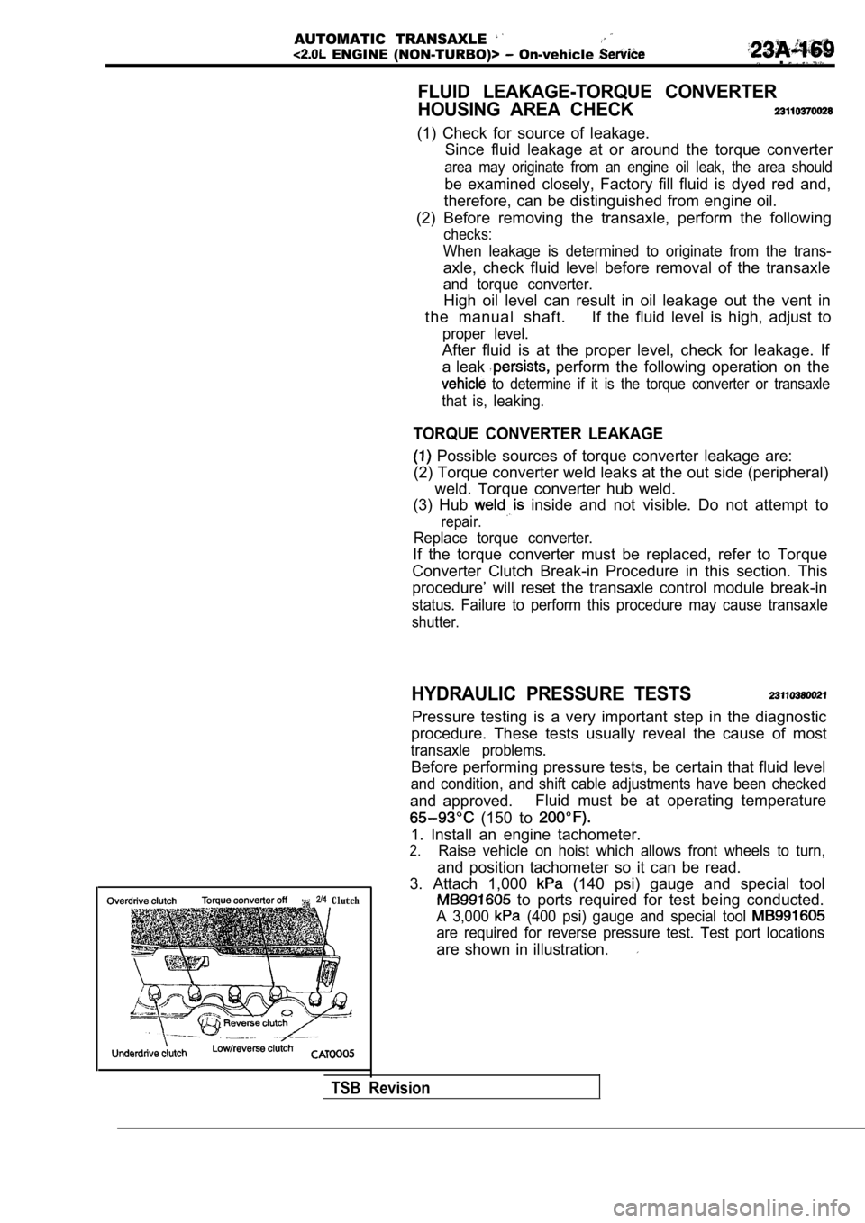
are shown in illustration.
TSB Revision