warning light MITSUBISHI SPYDER 1990 Service Repair Manual
[x] Cancel search | Manufacturer: MITSUBISHI, Model Year: 1990, Model line: SPYDER, Model: MITSUBISHI SPYDER 1990Pages: 2103, PDF Size: 68.98 MB
Page 22 of 2103
GENERAL before Service
PRECAUTIONS BEFORE SERVICE.
SUPPLEMENTAL RESTRAINT SYSTEM
1. to follow when servicing SRS
(1) Be sure to read GROUP Supplemental Restraint System
For safe operations, please follow the directions a nd heed all
(2) Always use the designated special tools and tes t equipment.
(3) Wait at least 60 seconds after disconnecting the battery cable before” further work;
The SRS system is designed to retain enough voltage to deploy the air bag even after the battery
has been disconnected. Serious injury may result from unintended air bag deployment if work
is done on the SRS system immediately after the bat tery cable is disconnected.
(4) Never attempt to disassemble or repair the SRS components (SRS-ECU air bag module and
clock spring). If faulty, replace it.
(5) Warning labels must be heeded when servicing or handling SRS components. Warning labels
are located in the following locations.
Sun visor
l Glove box
. S R S - E C U
l Steering wheel
l Air bag module
l Clock spring
l Steering gear and linkage clamp
(6) Store components removed from the SRS
a clean and dry place.
The air bag module should be stored on a flat surfa ce and placed so that the pad surface is’
facing upward.
Do not place anything on top of it.
(7) Be sure to deploy the air bag before disposing of the air bag’module or disposing of a vehicle
equipped with an air bag. (Refer to GROUP
Air Bag Module Disposal Procedures.)
(8) Whenever you finish servicing the
check the SRS warning light operation to make sure
that the system functions properly.
2.Observe the following when carrying out operations on places where SRS components are installed,’
.,
including operations not directly related to the SR S air bag.
(1) When removing or installing parts do not allow any impact or shock to the SRS components.
(2) SRS components should not be subjected to heat over so remove the SRS compo-
nents before drying or baking the vehicle after painting.
After re-installing them, check the SRS warning lig ht operation to make sure that the system
functions properly.
SERVICING THE ELECTRICAL SYSTEM
1. Note the following before proceeding with work o n the
electrical system.
Note that the following must never be done:
Unauthorized modifications of any electrical device or
wiring, because such modifications might lead to a vehicle
malfunction, over-capacity or short-circuit that co uld result
in a fire in the vehicle.
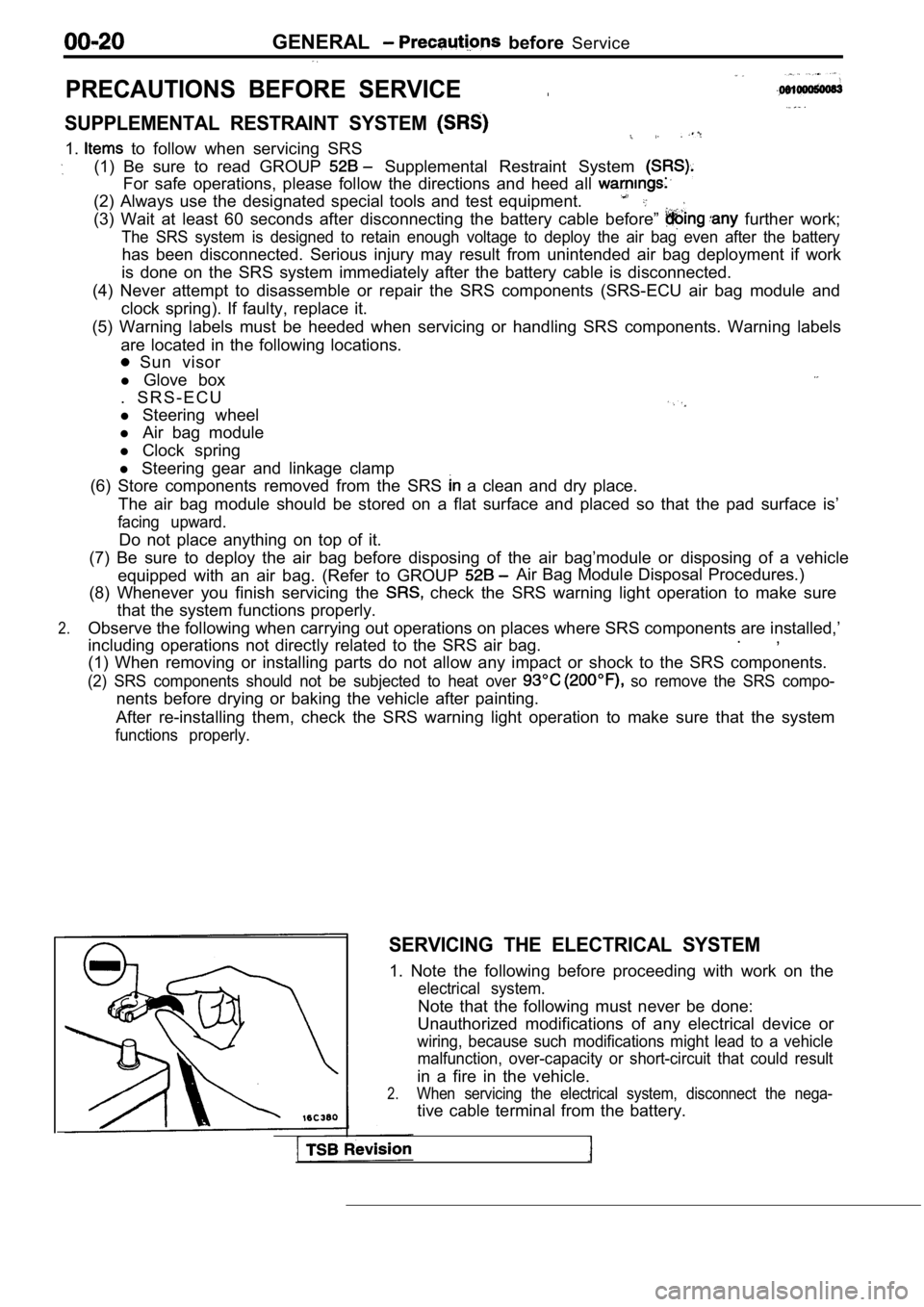
2.When servicing the electrical system, disconnect th e nega-
tive cable terminal from the battery.
Page 53 of 2103
GENERAL Maintenance
21 SYSTEM component
damage, to wiring,
harness, etc.)
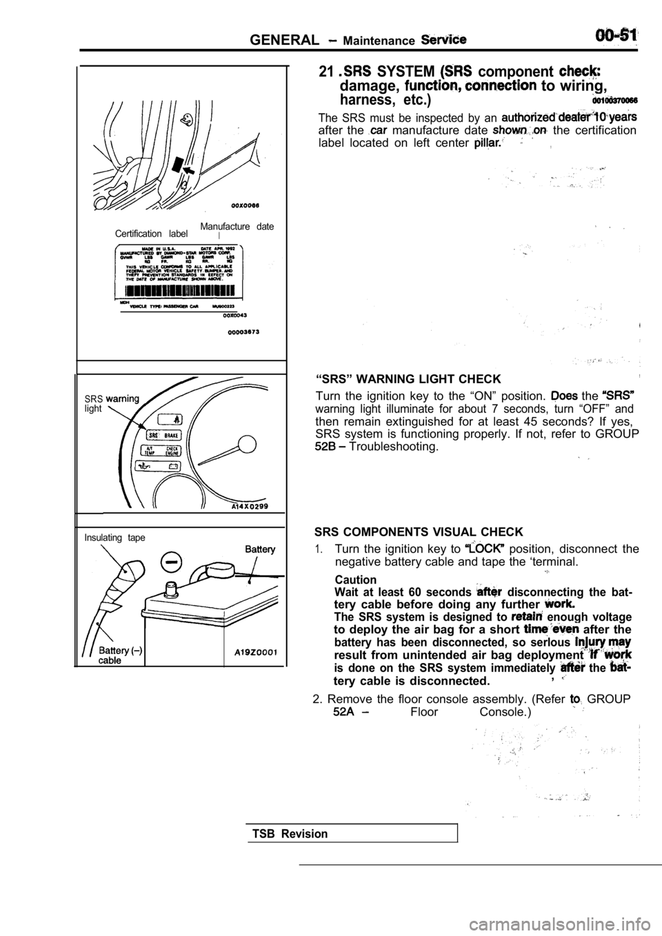
Certification labelManufacture dateI
SRSlight
Insulating tape
The SRS must be inspected by an
after the manufacture date the certification
label located on left center
,
“SRS” WARNING LIGHT CHECK,
Turn the ignition key to the “ON” position. the
warning light illuminate for about 7 seconds, turn “OFF” and
then remain extinguished for at least 45 seconds? I f yes,
SRS system is functioning properly. If not, refer t o GROUP
Troubleshooting.
SRS COMPONENTS VISUAL CHECK
1.Turn the ignition key to position, disconnect the
negative battery cable and tape the ‘terminal.
Caution
Wait at least 60 seconds
disconnecting the bat-
tery cable before doing any further
The SRS system is designed to enough voltage
to deploy the air bag for a short after the
battery has been disconnected, so serlous
result from unintended air bag deployment
is done on the SRS system immediately the
tery cable is disconnected. ,
2. Remove the floor console assembly. (Refer GROUP
Floor Console.)
TSB Revision
Page 519 of 2103

ENGINE (TURBO)
ENGINE>
DIAGNOSTIC TEST MODEl When an abnormality is detected in one
of the sensors or actuators related to emis-
sion control, the CHECK
FUNCTION INDICATOR LAMP illuminates
as a warning to the driver.
l When an abnormality is detected in one
of the’ sensors or actuators, a
OTHER CONTROL FUNCTIONS
1. Fuel Pump Control
Turns the fuel pump relay ON current
is supplied to the fuel pump while the engine
is cranking or running.
2. A/C Compressor Clutch Relay Control Turns the A/C compressor clutch ON and
OFF.
3. Fan Relay Control
The radiator fan and condenser fan speeds
are controlled in response to the engine
coolant temperature and vehicle speed.
4. Fuel
Control
Supplies current to fuel pressure solenoid
coil to raise the fuel pressure so that the
fuel does not vaporize when the engine
is started while it is warm.
trouble code ‘the,,
normality is output.
lThe RAM data inside the that
to the sensors and actuators can be read’
by
scan’ tool.
addition, the actuators can be controlled
under certain
5. Charge Control
Controls the intake charge pressure by con-
trolling the duty of the turbocharger
gate solenoid!
6. Intake Pressure Gauge’ Control Indicates the intake charge pressure on
the
7. Generator Output Current Control
Prevents generator output current from in-
creasing idle speed from
dropping at times such as when the head-
lights are turned on.
8.Evaporative Emission Purge Solenoid Con-
trol Engine (TURBO)>
Refer to
17.
Evaporative Emission Purge Solenoid Con-
trol GROUP 17.
9. EGR Solenoid’ Control
Refer to GROUP
,,
,
TSB Revision
Page 741 of 2103
CONTENTS
AUTO-CRUISE CONTROL SYSTEM
. . . . . . . . . . . . . . . . . . . . . . . . . . . . . . . . . . . . .7
AUTO-CRUISE CONTROL* . . . . . . . . . . . . . . 40
GENERAL INFORMATION . . . . . . . . . . . . . . . . 7
ON-VEHICLE SERVICE. . . . . . . . . . . . . . . . . 33
Auto-cruise Control Cable Check and
Adjustment . . . . . . . . . . . . . . . . . . . . . . . . . . . . . .
33
Auto-cruise Control Component Check . . . . . 37
Auto-cruise Control System Operation Check
. . . . . . . . . . . . . . . . . . . . . . . . . . . . . . . . . . . . . . . . .
35
SERVICE SPECIFICATIONS . . . . . . . . . . . . . 8
SPECIAL TOOLS . . . . . . . . . . . . . . . . . . . . . . . . 8
TROUBLESHOOTING
ENGINE (NON-TURBO)> . . . . . . . . . . . 9
TROUBLESHOOTING
(TURBO) AND ENGINE> . . . . .
EMISSION CONTROL’ SYSTEM
. . . . .
CATALYTIC . . . . . . . . . . . . . .
General Information . . . . . . . . . . . . . . . . . . 57
EVAPORATIVE EMISSION .
SYSTEM. . . . . . . . . . . . . . . .
Air Conditioning . . . . . . . . . . . . . . . . . . . 52
Component Location
. . . . . . . . . . . . . . . . . .
Engine Coolant Temperature Sensor
Intake Air Temperature Sensor . . . . . . . . . . . . 52
WARNINGS REGARDING SERVICING OF SUPPLEMENTAL RESTRA INT SYSTEM (SRS) EQUIPPED
WARNING!
(1) Improper serviceor maintenance of any component of the or any SRS-related can to injuryorcleathtoservicepersonnel (from inadvertentfiring the SRS inoperative).
(2) Service or maintenance of any SRS component or SRS-related component must be performed only
MITSUBISHI dealer.
(3) MITSUBISHI dealer personnel must thoroughly rev iew this manual, and especially its GROUP
Restraint System (SRS) and GROUP 00 Maintenance Service, before any service or maintenance of any
componentof the SRS or any SRS-related component.
NOTEJhe includes the following components: warning light, air bag module, clock components (that may have to be removed/installed in connection with or areIndicated in the table of contents by an asterisk
Page 819 of 2103
Evaporative
emission
canister side
Rubber hose
F U E L T A N K ,
I N S T A L L A T I O N
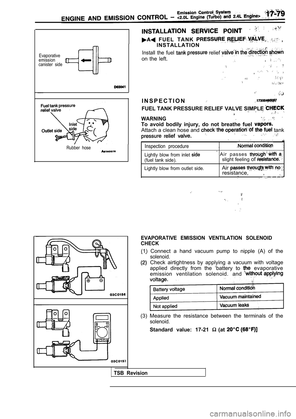
Install the fuel relief
on the left.,
,
I..- ,
I N S P E C T I O N
FUEL TANK PRESSURE RELIEF VALVE SIMPLE .,
WARNING
To avoid bodily injury, do not breathe fuel
Attach a clean hose and tank
Inspection procedure,
Lightly blow from inlet A i r p a s s e s
(fuel tank side).slight feeling of
Lightly blow from outlet side.Air
resistance, , .
EVAPORATIVE EMISSION VENTILATION SOLENOID
CHECK
(1) Connect a hand vacuum pump to nipple (A) of the
solenoid.
Check airtightness by applying a vacuum with voltag e
applied directly from the ‘battery to
evaporative
emission ventilation solenoid. and
(3) Measure the resistance between the terminals of the
solenoid.
Standard value: 17-21 (at
TSB Revision
Page 859 of 2103
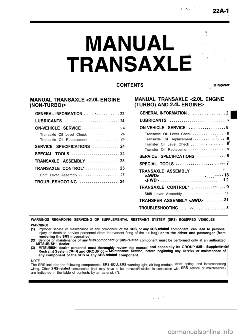
CONTENTS
MANUAL TRANSAXLE ENGINEMANUAL TRANSAXLE ENGINE
(NON-TURBO)>(TURBO) AND ENGINE>
GENERAL INFORMATION . . . . . . . . . . . . . . 22GENERAL INFORMATION . . . . . . . . . . . . . . . .
2
LUBRICANTS. . . . . . . . . . . . . . . . . . . . . . . . . . 24LUBRICANTS. . . . . . . . . . . . . . . . . . . . . . . . . . .6
ON-VEHICLE SERVICE. . . . . . . . . . . . . . . . .
2 4
Transaxle Oil Level Check . . . . . . . . . . . . . . . .
24
Transaxle Oil Replacement . . . . . . . . . . . . . . .
24
SERVICE SPECIFICATIONS. . . . . . . . . . . . .24
SPECIAL TOOLS. . . . . . . . . . . . . . . . . . . . . . .24
TRANSAXLE ASSEMBLY. . . . . . . . . . . . . . .28
TRANSAXLE CONTROL*. . . . . . . . . . . . . . . .25ON-VEHICLE SERVICE
. . . . . . . . . . . . . . . . 8
Shift Lever Assembly
. . . . . . . . . . . . . . . . . . . . .
27
TROUBLESHOOTING. . . . . . . . . . . . . . . . . . .24
Transaxle Oil Level Check . . . . . . . . . . . . . . . . .8
Transaxle Oil Replacement
. . . . . . . . . . .. . .
Transfer Oil Level Check ...... . . . . . . . . . . .
Transfer Oil Replacement. . . . . . . . . . . . . . . . . .8
SERVICE SPECIFICATIONS. . . . . . . . . . ...
SPECIAL TOOLS 7. . . . . . . . . . . . . . . . . .
TRANSAXLE ASSEMBLY
. . . . . . . . . . . . . . . . . . . . ... . . .
. . . . . . . . . . . . . . . . . . . . . . . . . . . .
. . 1 2
TRANSAXLE CONTROL*... . . . . . . . .
Shift Lever Assembly. . . . . . . . . . . . . . . . . . . . . .1 1
TRANSFER ASSEMBLY . . . . . . . .
TROUBLESHOOTING . . . . . . . . . . . . . . . . . .
WARNINGS REGARDING SERVICING OF SUPPLEMENTAL RESTRA
INT SYSTEM (SRS) EQUIPPED VEHICLES
WARNING!
(1)Improper service or maintenance of any component of the or any component, can lead to personalinjury or death to service personnel (from inadvertent firing of the air bag) or to the driver and passenger (from
rendering the inoperative).Service or maintenance of any or component must be performed only at an authorized MITSUBISHI dealer.(3)MITSUBISHI dealer personnel must thoroughly review this manual,and especially its GROUP
Restraint System and GROUP 00 Maintenance Service, before beginning any or maintenance of
any component of the or any component.
NOTEThe SRS includes the following components: warning light, air bag module,clock spring, and interconnecting
wiring. Other
components (that may have to be removed/installed in connection with service or maintenance)
are indicated in the table of contents by an asterisk
Page 1009 of 2103
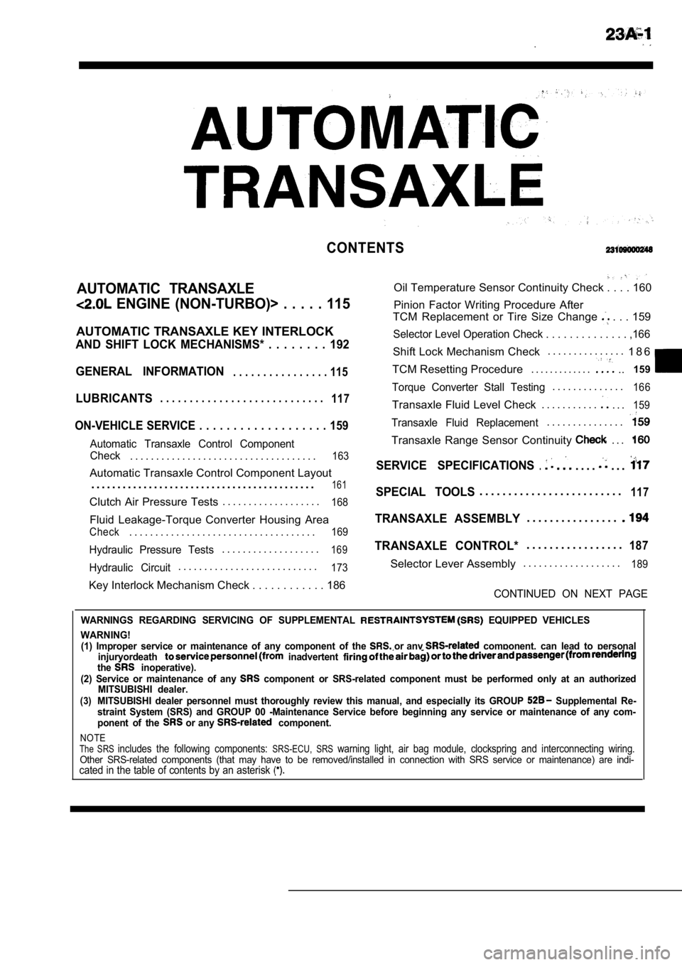
CONTENTS
AUTOMATIC TRANSAXLE
ENGINE (NON-TURBO)> . . . . . 115
AUTOMATIC TRANSAXLE KEY INTERLOCK
AND SHIFT LOCK MECHANISMS* . . . . . . . . 192
GENERAL INFORMATION
. . . . . . . . . . . . . . . . 115
LUBRICANTS. . . . . . . . . . . . . . . . . . . . . . . . . . . .117
ON-VEHICLE SERVICE . . . . . . . . . . . . . . . . . . . 159
Automatic Transaxle Control Component
Oil Temperature Sensor Continuity Check . . . . 160
Pinion Factor Writing Procedure After
TCM Replacement or Tire Size Change
. . . 159
Selector Level Operation Check . . . . . . . . . . . . . . ,166
Shift Lock Mechanism Check. . . . . . . . . . . . . . .
1 8 6
TCM Resetting Procedure . . . . . . . . . . . . .
..159
Torque Converter Stall Testing. . . . . . . . . . . . . .166
Transaxle Fluid Level Check . . . . . . . . . . .. . .159
Transaxle Fluid Replacement. . . . . . . . . . . . . . .
Transaxle Range Sensor Continuity . . .
Check. . . . . . . . . . . . . . . . . . . . . . . . . . . . . . . . . . . .163SERVICE SPECIFICATIONS.. . . .. . .Automatic Transaxle Control Component Layout
. . . . . . . . . . . . . . . . . . . . . . . . . . . . . . . . . . . . . . . . . . .
161SPECIAL TOOLS. . . . . . . . . . . . . . . . . . . . . . . . .117Clutch Air Pressure Tests . . . . . . . . . . . . . . . . . . .168
Fluid Leakage-Torque Converter Housing Area
Check. . . . . . . . . . . . . . . . . . . . . . . . . . . . . . . . . . . .169
Hydraulic Pressure Tests. . . . . . . . . . . . . . . . . . .169
Hydraulic Circuit. . . . . . . . . . . . . . . . . . . . . . . . . . .173
TRANSAXLE ASSEMBLY. . . . . . . . . . . . . . . .
TRANSAXLE CONTROL*. . . . . . . . . . . . . . . . .187
Selector Lever Assembly. . . . . . . . . . . . . . . . . . .189
Key Interlock Mechanism Check . . . . . . . . . . .
. 186CONTINUED ON NEXT PAGE
WARNINGS REGARDING SERVICING OF SUPPLEMENTAL EQUIPPED VEHICLES
WARNING! (1) Improper service or maintenance of any componen t of the
or any component, can lead to personal
injuryordeath inadvertent the inoperative).
(2) Service or maintenance of any component or SRS-related component must be perform ed only at an authorized
MITSUBISHI dealer.
(3)MITSUBISHI dealer personnel must thoroughly review this manual, and especially its GROUP Supplemental Re-
straint System (SRS) and GROUP 00 -Maintenance Serv ice before beginning any service or maintenance of any com-
ponent of the
or any component.
NOTEThe SRS includes the following components: SRS-ECU, SRS warning light, air bag module, clockspring and inte rconnecting wiring.Other SRS-related components (that may have to be removed/installed in connection with SRS service or maintenance) are indi-cated in the table of contents by an asterisk
Page 1059 of 2103
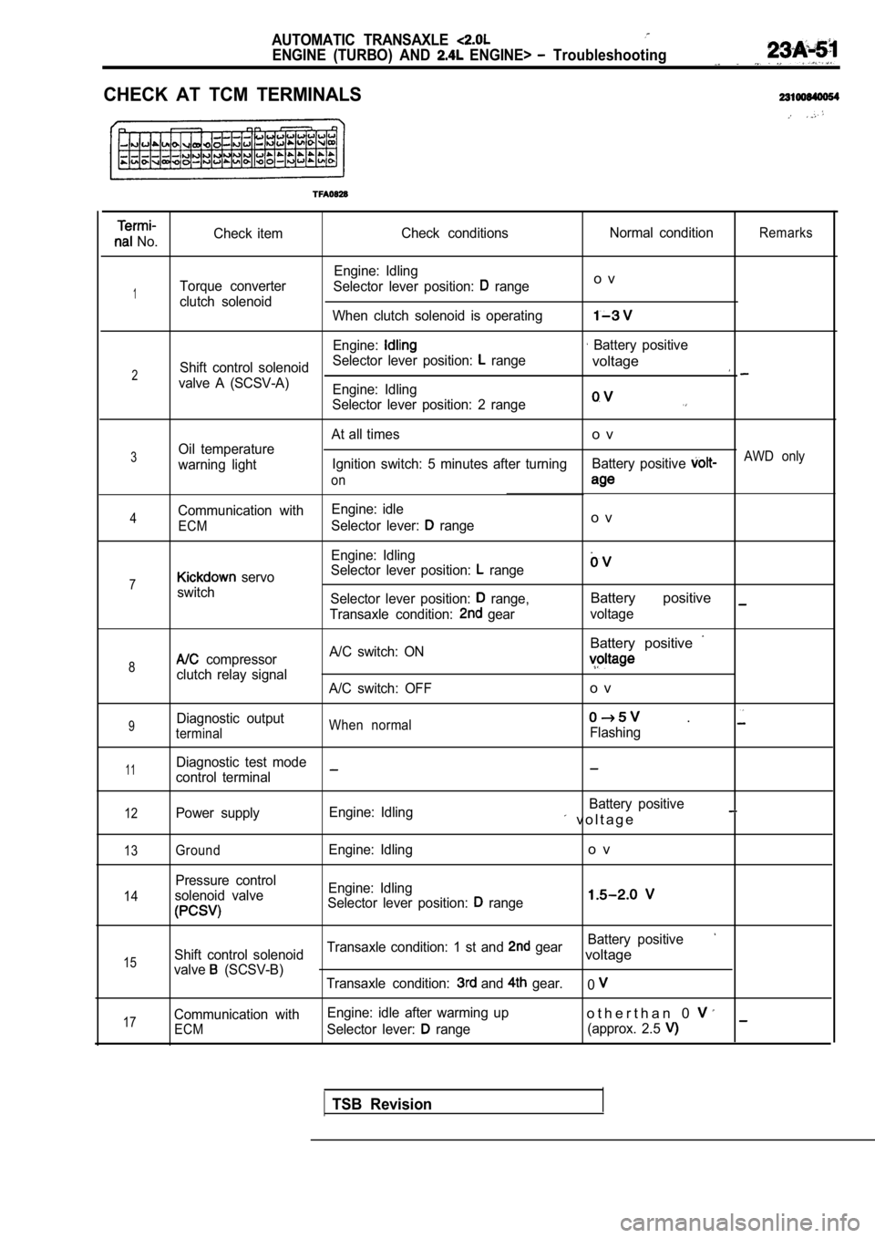
AUTOMATIC TRANSAXLE
ENGINE (TURBO) AND ENGINE> Troubleshooting
CHECK AT TCM TERMINALS
No.Check item
Check conditions Normal conditionRemarks
Engine: Idling
Torque converter Selector lever position:
rangeo v
1clutch solenoid
When clutch solenoid is operating
Engine: Battery positive
Shift control solenoid Selector lever position:
range
2voltage
valve A (SCSV-A)
Engine: Idling
Selector lever position: 2 range
At all timeso v
3Oil temperature
warning light Ignition switch: 5 minutes after turning
Battery positive AWD only
on
Communication with Engine: idle4Selector lever: rangeo vECM
Engine: Idling
Selector lever position:
range7 servo
switch Selector lever position:
range,Battery positive
Transaxle condition: gearvoltage
Battery positive
8 compressor A/C switch: ON
clutch relay signal
A/C switch: OFFo v
9Diagnostic outputWhen normal .
terminalFlashing
11Diagnostic test mode
control terminal
12Power supply Engine: Idling Battery positive v o l t a g e
13
14
15
17
GroundEngine: Idlingo v
Pressure control
solenoid valve Engine: Idling
Selector lever position:
range
Battery positive
Shift control solenoid Transaxle condition: 1 st and gearvoltage
valve (SCSV-B)
Transaxle condition: and gear.0
Communication with Engine: idle after warming upo t h e r t h a n 0
ECMSelector lever: range
(approx. 2.5
TSB Revision
Page 1148 of 2103
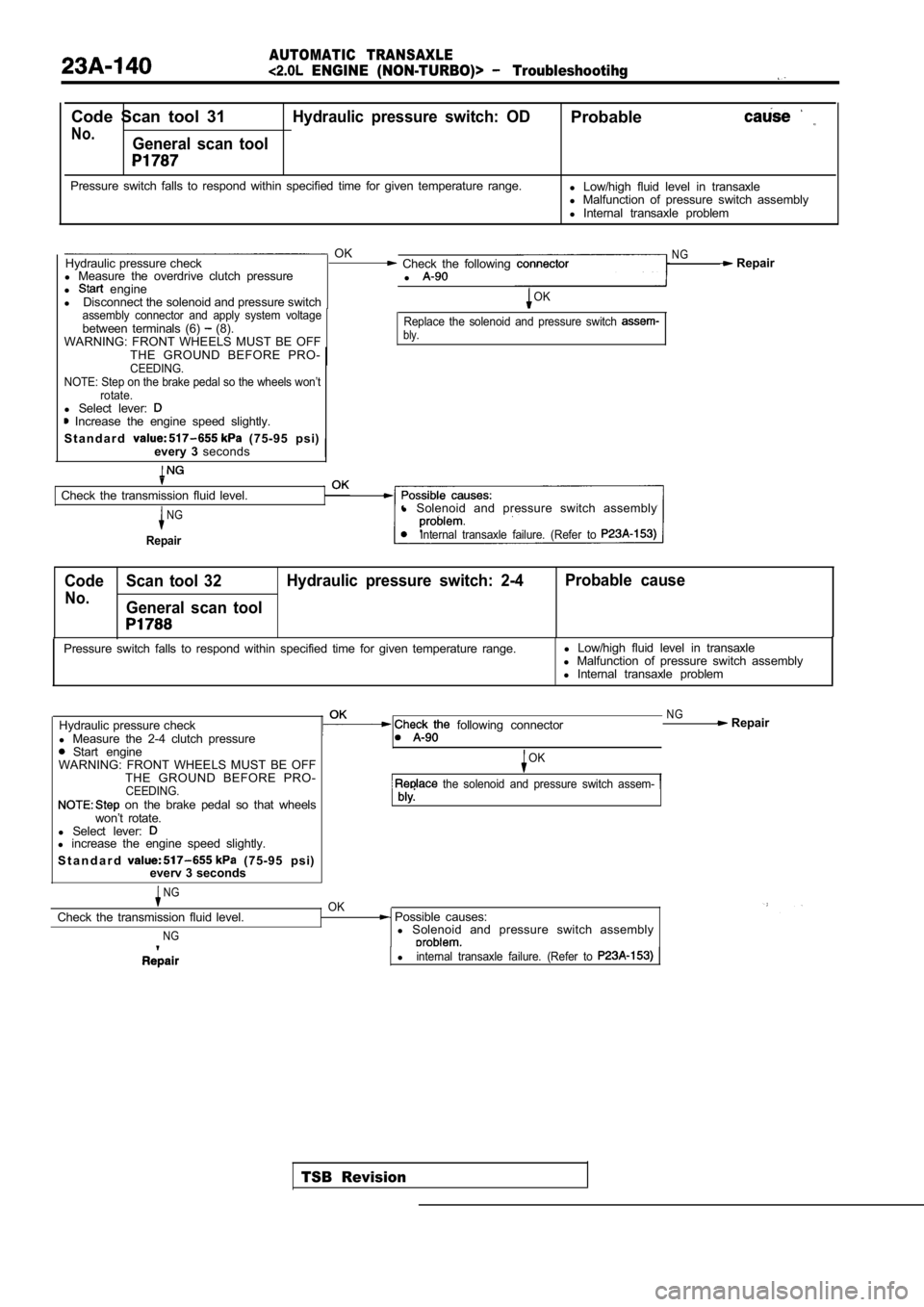
AUTOMATIC TRANSAXLE
ENGINE (NON-TURBO)> Troubleshootihg
Code Scan tool 31Hydraulic pressure switch: ODProbable
No.General scan tool
Pressure switch falls to respond within specified time for given temperature range.
l Low/high fluid level in transaxle
l Malfunction of pressure switch assembly
l Internal transaxle problem
OKNGHydraulic pressure check Check the following Repair
l Measure the overdrive clutch pressure
l
l engine
l Disconnect the solenoid and pressure switchOK
assembly connector and apply system voltage
between terminals (6) (8).
WARNING: FRONT WHEELS MUST BE OFFReplace the solenoid and pressure switch bly.
THE GROUND BEFORE PRO-CEEDING.
NOTE: Step on the brake pedal so the wheels won’t rotate.
l Select lever: Increase the engine speed slightly.
S t a n d a r d
(75-95 psi)
every 3 seconds
Check the transmission fluid level.
NG
Repair
l Solenoid and pressure switch assembly
Internal transaxle failure. (Refer to
Code Scan tool 32 Hydraulic pressure switch: 2-4 Probable cause
No.General scan tool
TSB Revision
Pressure switch falls to respond within specified t
ime for given temperature range.l
Low/high fluid level in transaxle
l Malfunction of pressure switch assembly
l Internal transaxle problem
Hydraulic pressure check
l Measure the 2-4 clutch pressure
Start engine
following connector
WARNING: FRONT WHEELS MUST BE OFF THE GROUND BEFORE PRO-
CEEDING. on the brake pedal so that wheels
won’t rotate.
l Select lever:
l increase the engine speed slightly.
S t a n d a r d
(75-95 psi)
everv 3 seconds
NGOK
NG Repair
OK
the solenoid and pressure switch assem-
Check the transmission fluid level.
NG
Possible causes:
l Solenoid and pressure switch assembly
linternal transaxle failure. (Refer to
Page 1174 of 2103
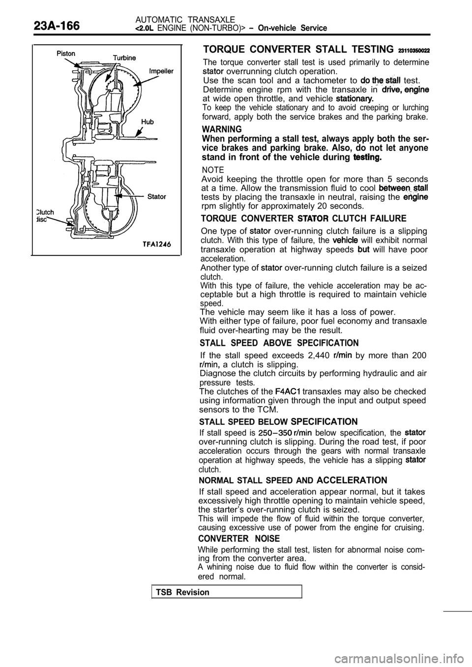
AUTOMATIC TRANSAXLE
ENGINE (NON-TURBO)> On-vehicle Service
TORQUE CONVERTER STALL TESTING
The torque converter stall test is used primarily to determine
overrunning clutch operation.
Use the scan tool and a tachometer to
test.
Determine engine rpm with the transaxle in
at wide open throttle, and vehicle
To keep the vehicle stationary and to avoid creepin g or lurching
forward, apply both the service brakes and the parking brake.
WARNING
When performing a stall test, always apply both the ser-
vice brakes and parking brake. Also, do not let any one
stand in front of the vehicle during
NOTE
Avoid keeping the throttle open for more than 5 seconds
at a time. Allow the transmission fluid to cool
tests by placing the transaxle in neutral, raising the
rpm slightly for approximately 20 seconds.
TORQUE CONVERTER CLUTCH FAILURE
One type of over-running clutch failure is a slipping
clutch. With this type of failure, the will exhibit normal
transaxle operation at highway speeds will have poor
acceleration.
Another type of over-running clutch failure is a seized
clutch.
With this type of failure, the vehicle acceleration may be ac-
ceptable but a high throttle is required to maintai n vehicle
speed.
The vehicle may seem like it has a loss of power.
With either type of failure, poor fuel economy and transaxle
fluid over-hearting may be the result.
STALL SPEED ABOVE SPECIFICATION
If the stall speed exceeds 2,440 by more than 200
a clutch is slipping.
Diagnose the clutch circuits by performing hydrauli c and air
pressure tests.
The clutches of the transaxles may also be checked
using information given through the input and outpu t speed
sensors to the TCM.
STALL SPEED BELOW SPECIFICATION
If stall speed is below specification, the
over-running clutch is slipping. During the road te st, if poor
acceleration occurs through the gears with normal t ransaxle
operation at highway speeds, the vehicle has a slip ping
clutch.
NORMAL STALL SPEED AND ACCELERATION
If stall speed and acceleration appear normal, but it takes
excessively high throttle opening to maintain vehic le speed,
the starter’s over-running clutch is seized.
This will impede the flow of fluid within the torqu e converter,
causing excessive use of power from the engine for cruising.
CONVERTER NOISE
While performing the stall test, listen for abnormal noise com-
ing from the converter area.
A whining noise due to fluid flow within the conver ter is consid-
ered normal.
TSB Revision