wheel alignment MITSUBISHI SPYDER 1990 Service Repair Manual
[x] Cancel search | Manufacturer: MITSUBISHI, Model Year: 1990, Model line: SPYDER, Model: MITSUBISHI SPYDER 1990Pages: 2103, PDF Size: 68.98 MB
Page 55 of 2103
G E N E R A L Maintenance
Protective tube
harness
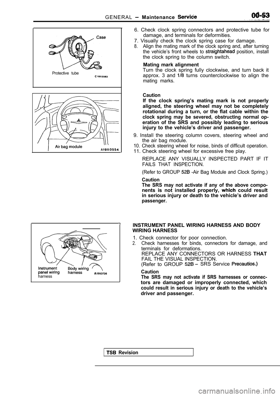
6. Check clock spring connectors and protective tube for
damage, and terminals for deformities.
7. Visually check the clock spring case for damage.
8.Align the mating mark of the clock spring and, afte r turning
the vehicle’s front wheels to
position, install
the clock spring to the column switch.
Mating mark alignment
Turn the clock spring fully clockwise, and turn bac k it
approx. 3 and
turns counterclockwise to align the
mating marks.
Caution
If the clock spring’s mating mark is not properly
aligned, the steering wheel may not be completely
rotational during a turn, or the flat cable within the
clock spring may be severed, obstructing normal op-
eration of the SRS and possibly leading to serious
injury to the vehicle’s driver and passenger.
9. Install the steering column covers, steering whe el and
the air bag module.
10. Check steering wheel for noise, binds of diffic ult operation.
11. Check steering wheel for excessive free play.
REPLACE ANY VISUALLY INSPECTED PART IF IT
FAILS THAT INSPECTION.
(Refer to GROUP
-Air Bag Module and Clock Spring.)
Caution
The SRS may not activate if any of the above compo-
nents is not installed properly, could result
in serious injury or death to the vehicle’s driver and
passenger.
INSTRUMENT PANEL WIRING HARNESS AND BODY
WIRING HARNESS
1. Check connector for poor connection.
2.Check harnesses for binds, connectors for damage, a nd
terminals for deformations.
REPLACE ANY CONNECTORS OR HARNESS THAT
FAIL THE VISUAL INSPECTION.
(Refer to GROUP
SRS Service
Caution
The SRS may not activate if SRS harnesses or connec -
tors are damaged or improperly connected, which
could result in serious injury or death to the vehicle’s
driver and passenger.
Revision
Page 369 of 2103
E N G I N E O V E R H A U L Flywheel
S h a n k l e n g t h
Arrow
CAP B E A R I N G C A P B O L T
INSTALLATION
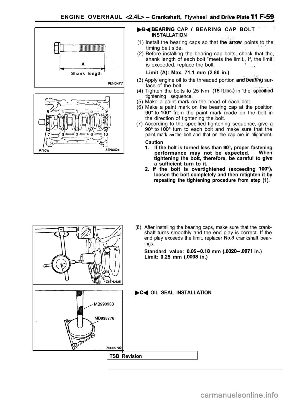
(1) Install the bearing caps so that points to the
timing belt side.
(2) Before installing the bearing cap bolts, check that the,
shank length of each bolt “meets the limit., If, th e limit’
is exceeded, replace the bolt.
Limit (A): Max. 71.1 mm (2.80 in.)
(3) Apply engine oil to the threaded portion
sur-
face of the bolt.
(4) Tighten the bolts to 25 Nm
in ‘the’
tightening sequence.
(5) Make a paint mark on the head of each bolt.
(6) Make a paint mark on the bearing cap at the pos ition
to from the paint mark made on the bolt in
the direction of tightening the bolt.
(7) According to the specified tightening sequence, give a
to turn to each bolt and make sure that the
paint mark onthe bolt and that on the cap are in alignment.
Caution
If the bolt is turned less than proper fastening
performance may not be expected.When
tightening the bolt, therefore, be careful to
a sufficient turn to it.
2. If the bolt is overtightened (exceeding
loosen the bolt completely and then retighten it by
repeating the tightening procedure from step (1).
(8)After installing the bearing caps, make sure that t he crank-
shaft turns smoothly and the end play is correct. I f the
end play exceeds the limit, replacer crankshaft bear-
ings.
Standard value: mm in.)
Limit: 0.25 mm
in.)
OIL SEAL INSTALLATION
998776
TSB Revision
Page 734 of 2103
INTAKE AND EXHAUST Exhaust Manifold ENGINE (Turbo)>
Identification holeExhaust
manifold
INSTALLATION SERVICE POINTS
TURBOCHARGER ASSEMBLY
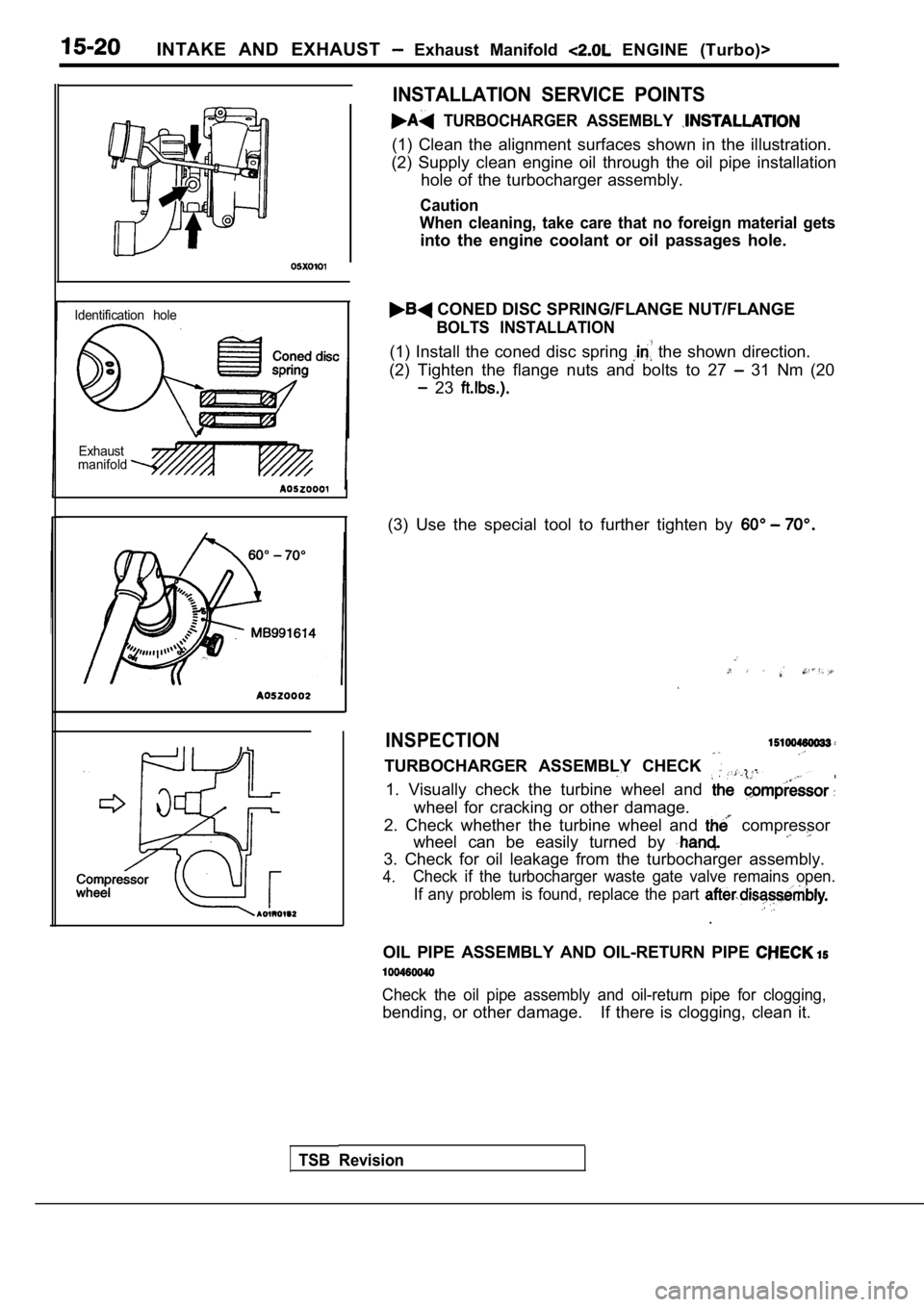
(1) Clean the alignment surfaces shown in the illus tration.
(2) Supply clean engine oil through the oil pipe in stallation
hole of the turbocharger assembly.
Caution
When cleaning, take care that no foreign material g ets
into the engine coolant or oil passages hole.
CONED DISC SPRING/FLANGE NUT/FLANGE
BOLTS INSTALLATION
(1) Install the coned disc spring the shown direction.
(2) Tighten the flange nuts and bolts to 27
31 Nm (20
23
(3) Use the special tool to further tighten by
INSPECTION
TURBOCHARGER ASSEMBLY CHECK . .
1. Visually check the turbine wheel and
wheel for cracking or other damage.
2. Check whether the turbine wheel and
compressor
wheel can be easily turned by
3. Check for oil leakage from the turbocharger asse mbly.
4.Check if the turbocharger waste gate valve remains open.
If any problem is found, replace the part
.
OIL PIPE ASSEMBLY AND OIL-RETURN PIPE
Check the oil pipe assembly and oil-return pipe for clogging,
bending, or other damage. If there is clogging, clea n it.
TSB Revision
Page 1159 of 2103
AUTOMATIC .
.
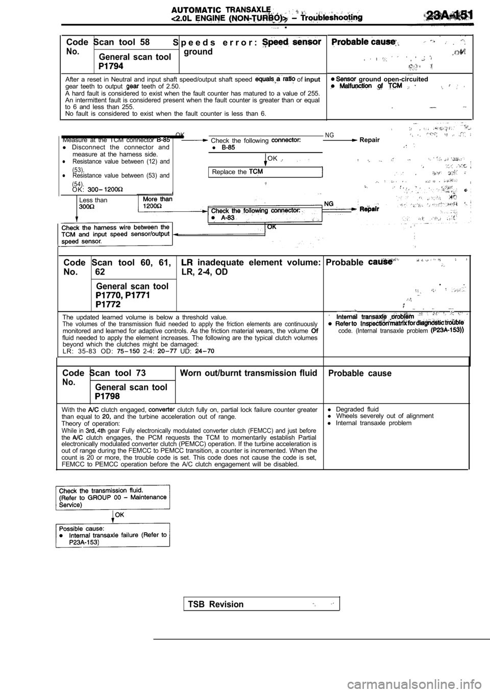
Code Scan tool 58 S p e e d s e r r o r :
No.General scan toolground
After a reset in Neutral and input shaft speed/outp
ut shaft speed of input
gear teeth to output teeth of 2.50.
A hard fault is considered to exist when the fault counter has matured to a value of 255.
An intermittent fault is considered present when th e fault counter is greater than or equal
to 6 and less than 255. No fault is considered to exist when the fault coun ter is less than 6.
.
. , ,
. .
ground open-circuited
OKNGMeasure at the TCM connector Check the following Repair
l Disconnect the connector and
l
measure at the harness side.Resistance value between (12) andOKl
(53).lResistance value between (53) andReplace the . (54).O K :.
Less than
Code Scan tool 60, 61, inadequate element volume: Probable
No. 62LR, 2-4, OD
General scan tool
.
The updated learned volume is below a threshold val ue..The volumes of the transmission fluid needed to app
ly the friction elements are continuouslymonitored and learned for adaptive controls. As the friction material wears, the volume Ofcode. (Internal transaxle problem fluid needed to apply the element increases. The fo llowing are the typical clutch volumes
beyond which the clutches might be damaged:
L R : 3 5 - 8 3 O D :
2-4: UD:
Code Scan tool 73Worn out/burnt transmission fluid Probable cause
No.General scan tool
With the clutch engaged, clutch fully on, partial lock failure counter greaterl
Degraded fluid
than equal to and the turbine acceleration out of range. l
Wheels severely out of alignment
Theory of operation: l
Internal transaxle problem
While in gear Fully electronically modulated converter clut ch (FEMCC) and just beforethe clutch engages, the PCM requests the TCM to moment arily establish Partial
electronically modulated converter clutch (PEMCC) o peration. If the turbine acceleration is
out of range during the FEMCC to PEMCC transition, a counter is incremented. When the
count is 20 or more, the trouble code is set. This code does not cause the code is set,
FEMCC to PEMCC operation before the A/C clutch enga gement will be disabled.
TSB Revision
Page 1551 of 2103
REAR AXLE On-vehicle Service
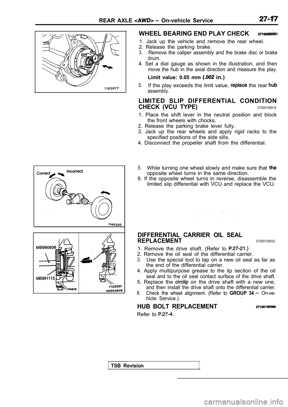
WHEEL BEARING END PLAY CHECK
1. Jack up the vehicle and remove the rear wheel.
2. Release the parking brake.
3.Remove the caliper assembly and the brake disc or b rake
drum.
4. Set a dial gauge as shown in the illustration, and then
move the hub in the axial direction and measure the play.
Limit value: 0.05 mm in.)
5.If the play exceeds the limit value, the rear
assembly.
LIMITED SLIP DIFFERENTIAL CONDITION
CHECK (VCU TYPE)27300100019
1. Place the shift lever in the neutral position an d block
the front wheels with chocks.
2. Release the parking brake lever fully.
3. Jack up the rear wheels and apply rigid racks to the
specified positions of the side sills.
4. Disconnect the propeller shaft from the differen tial.
5.While turning one wheel slowly and make sure that
opposite wheel turns in the same direction.
6. If the opposite wheel turns in reverse, disassem ble the
limited slip differential with VCU and replace the VCU.
DIFFERENTIAL CARRIER OIL SEAL
REPLACEMENT27200120022
1. Remove the drive shaft. (Refer to
2. Remove the oil seal of the differential carrier.
3.Use the special tool to tap on a new oil seal as fa r as
the end of the differential carrier.
4. Apply multipurpose grease to the lip section of the oil
seal and to the oil seal contact surface of the drive shaft.
5. Replace the on the drive shaft with a new one,
and then install the drive shaft onto the differential carrier.
6.Check the wheel alignment. (Refer to GROUP 34 On-ve-
hicle Service.)
HUB BOLT REPLACEMENT
Refer to
TSB Revision1
Page 1588 of 2103
WHEEL AND TIRE
Symptom
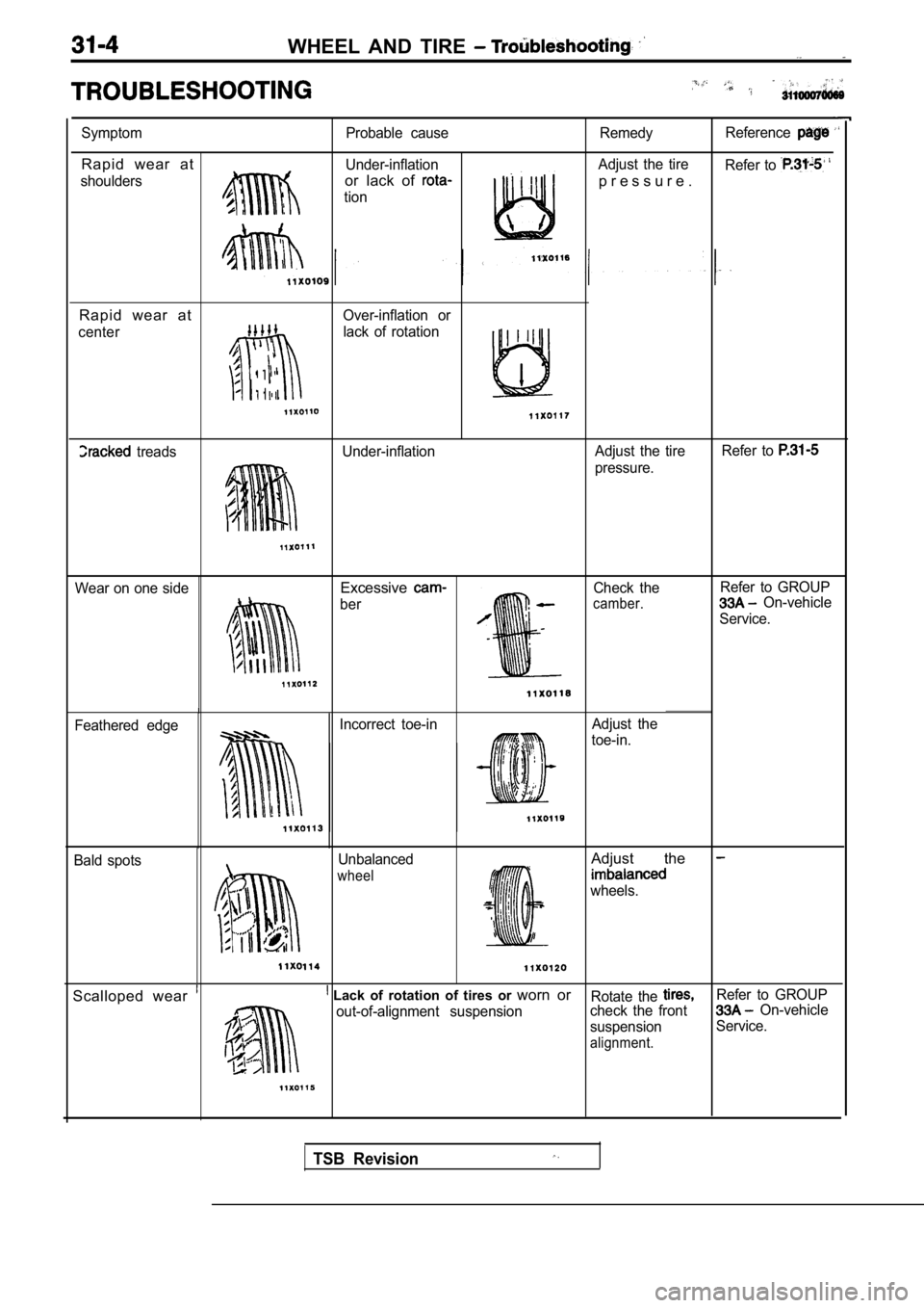
Rapid wear at
shouldersProbable cause
Under-inflationor lack of
tion
Remedy Reference
Adjust the tire
Refer to
p r e s s u r e .
Rapid wear at
Over-inflation or
center
lack of rotation
I
treads Under-inflation Adjust the tireRefer to
pressure.
Wear on one side
Excessive
ber Check thecamber.
Refer to GROUP On-vehicle
Service.
Feathered edge Incorrect toe-in
Adjust the
toe-in.
Bald spots Unbalanced
wheel
Adjust the
wheels.
Scalloped wear Lack of rotation of tires or
worn orRotate the Refer to GROUP
out-of-alignment suspension check the front On-vehicle
suspension Service.
alignment.
TSB Revision
Page 1601 of 2103
FRONT
CONTENTS
COMPRESSION LOWER ARM ANDSHOCK ABSORBER ASSEMBLY.. . . . . . . . 8
LATERAL LOWER ARM ASSEMBLIES . . . . . 11
SPECIAL TOOLS3
GENERAL INFORMATION. . . . . . . . . . . . . . . . . .2
STABILIZER BAR. . . . . . . . . . . . . . . ..*.......14
ON-VEHICLE SERVICE . . . . . . . . . . . . . . . . . . . . . 4
Front Wheel Alignment CheckTROUBLESHOOTING . . . . . . . . . . . . . . . . . . . . 4
and Adjustment . . . . . . . . . . . . . . . . . . . . . . . . . . . . . .4UPPER ARM ASSEMBLY . . . . . . . . . . . . . . . .
. . . 6
SERVICE SPECIFICATIONS . . . . . . . . . . . . . . . . . 3
Page 1604 of 2103
FRONT __
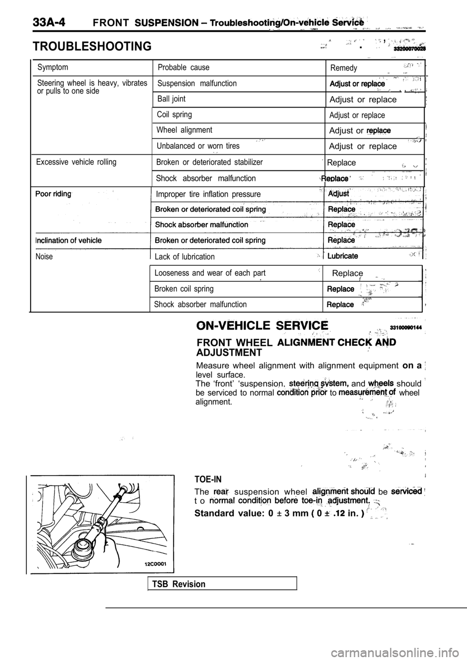
TROUBLESHOOTING
, .
SymptomProbable cause
Remedy
Steering wheel is heavy, vibratesSuspension malfunction
or pulls to one side, ,
Ball jointAdjust or replace
Coil spring
Wheel alignment
Unbalanced or worn tires Adjust or replace
Adjust or
Adjust or replace
Excessive vehicle rollingBroken or deteriorated stabilizer
Shock absorber malfunction
Replace
Improper tire inflation pressure
NoiseLack of lubrication
Looseness and wear of each part
.
Broken coil spring
Shock absorber malfunction
Replace
FRONT WHEEL
ADJUSTMENT
Measure wheel alignment with alignment equipment on a
level surface.
The ‘front’ ‘suspension, and should
be serviced to normal to wheel
alignment.
TOE-IN
The suspension wheel be
t o
Standard value: 0 3 mm 0 in.
TSB Revision
Page 1606 of 2103
FRONT SUSPENSION Upper Arm .
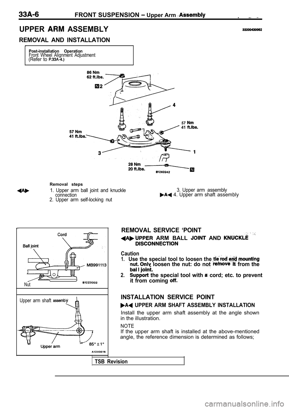
UPPER ASSEMBLY
REMOVAL AND INSTALLATION
Post-installation OperationFront Wheel Alignment Adjustment(Refer to
5741
Removal steps
1. Upper arm ball joint and knuckleconnection2. Upper arm self-locking nut3. Upper arm assembly
4. Upper arm shaft assembly
Nut
Upper arm shaft
REMOVAL SERVICE ‘POINT
ARM BALL AND
Caution
1.Use the special tool to loosen the
loosen the nut: do not from the
2. the special tool with cord; etc. to prevent
it from coming
INSTALLATION SERVICE POINT
UPPER ARM SHAFT ASSEMBLY INSTALLATION
Install the upper arm shaft assembly at the angle s hown
in the illustration.
NOTE
If the upper arm shaft is installed at the above-me ntioned
angle, the reference dimension is determined as fol lows;
TSB Revision
Page 1608 of 2103
F R O N T S U S P E N S I O N Upper Arm . ,
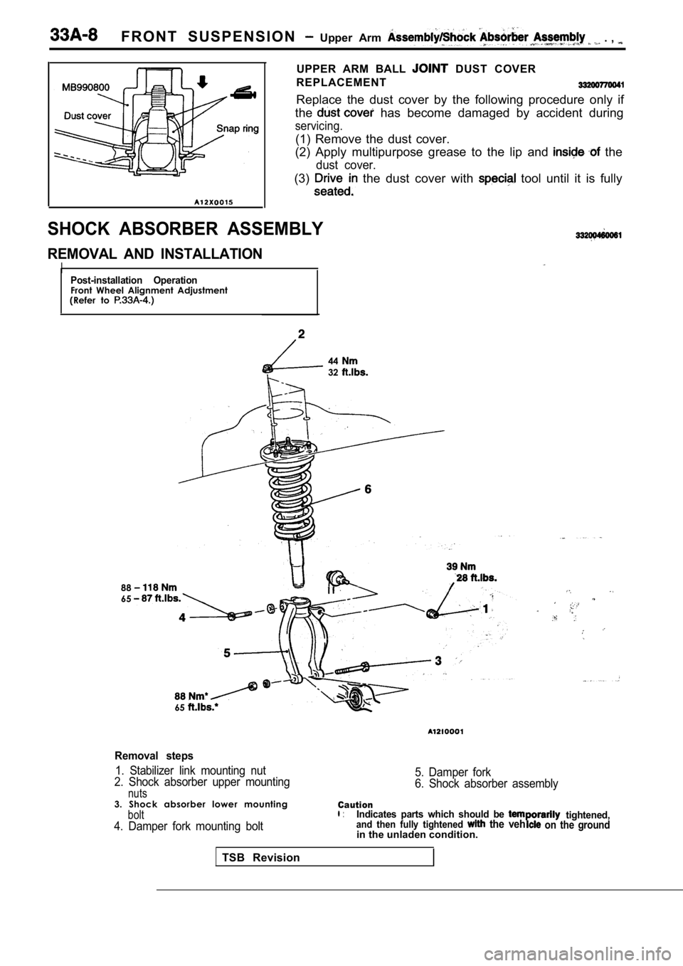
UPPER ARM BALL DUST COVER
REPLACEMENT
Replace the dust cover by the following procedure o nly if
the
has become damaged by accident during
servicing.
(1) Remove the dust cover.
(2) Apply multipurpose grease to the lip and
the
dust cover.
(3) the dust cover with tool until it is fully
.
SHOCK ABSORBER ASSEMBLY
REMOVAL AND INSTALLATION
I,Post-installation OperationFront Wheel Alignment Adjustment
(Refer to
8865
4432
65
Removal steps
1. Stabilizer link mounting nut
2. Shock absorber upper mounting
nuts
5. Damper fork
6. Shock absorber assembly
3. Shock absorber lower mounting
bolt4. Damper fork mounting bolt
Cautionl :Indicates parts which should be tightened,and then fully tightened the veh on the groundin the unladen condition.
TSB Revision