water pump MITSUBISHI SPYDER 1990 Service Repair Manual
[x] Cancel search | Manufacturer: MITSUBISHI, Model Year: 1990, Model line: SPYDER, Model: MITSUBISHI SPYDER 1990Pages: 2103, PDF Size: 68.98 MB
Page 3 of 2103
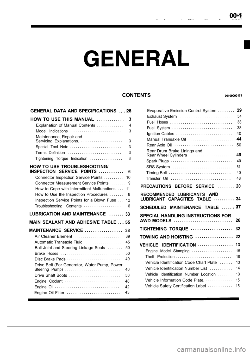
CONTENTS
GENERAL DATA AND SPECIFICATIONS. .
HOW TO USE THIS MANUAL. . . . . . . . . . . . .3
Explanation of Manual Contents. . . . . . . . . . . . . .4
Model Indications
. . . . . . . . . . . . . . . . . . . . . . . . . . .3
Maintenance, Repair and
Servicing Explanations. . . . . . . . . . . . . . . . . . . . . . .
3
Special Tool Note. . . . . . . . . . . . . . . . . . . . . . . . . . .3
Terms Definition. . . . . . . . . . . . . . . . . . . . . . . . . . . .3
Tightening Torque Indication. . . . . . . . . . . . . . . . .3
HOW TO USE TROUBLESHOOTING/
INSPECTION SERVICE POINTS. . . . . . . . . . . .6
Connector Inspection Service Points
. . . . . . . . . .10
Connector Measurement Service Points . . . . . . . .9
How to Cope with Intermittent Malfunctions . . .11
How to Use the Inspection Procedures
. . . . . . .
8
Inspection Service Points for a Blown Fuse . . .
12
Troubleshooting Contents. . . . . . . . . . . . . . . . . . . .6
LUBRICATION AND MAINTENANCE . . . . . . .33
MAIN SEALANT AND ADHESIVE TABLE
. .
MAINTENANCE SERVICE. . . . . . . . . . . . . . . . . .38
Air Cleaner Element. . . . . . . . . . . . . . . . . . . . . . . .39
Automatic Transaxle Fluid
. . . . . . . . . . . . . . . . . . .45
Ball Joint and Steering Linkage Seals
. . . . . . . .50
Brake Hoses.... . . . . . . . . . . . . . . . . . . . . . . . . . . .50
Disc Brake Pads. . . . . . . . . . . . . . . . . . . . . . . . . . . .49
Drive Belt (For Generator, Water Pump, Power
Steering Pump). . . . . . . . . . . . . . . . . . . . . . . . . . . . .40
Drive Shaft Boots
. . . . . . . . . . . . . . . . . . . . . . . . . . .50
Engine Coolant. . . . . . . . . . . . . . . . . . . . . . . . . . . . .48
Engine Oil. . . . . . . . . . . . . . . . . . . . . . . . . . . . . . . . . .42
Engine Oil Filter. . . . . . . . . . . . . . . . . . . . . . . . . . . .43
Evaporative Emission Control System . . . . . . . . .
Exhaust System. . . . . . . . . . . . . . . . . . . . . . . . . . . . .54
Fuel Hoses. . . . . . . . . . . . . . . . . . . . . . . . . . . . . . . . .38
Fuel System. . . . . . . . . . . . . . . . . . . . . . . . . . . . . . . .38
Ignition Cables. . . . . . . . . . . . . . . . . . . . . . . . . . . . . .
40
Manual Transaxle Oil . . . . . . . . . . . . . . . . . . . . . . . .
Rear Axle Oil. . . . . . . . . . . . . . . . . . . . . . . . . . . .
50
Rear Drum Brake Linings and
Rear Wheel Cylinders . . . . . . . . . . . . . . . . . . . . . . .
Spark Plugs. . . . . . . . . . . . . . . . . . . . . . . . . . . . . . . .40
SRS System . . . . . . . . . . . . . . . . . . . . . . . . . . . . . . .51
Timing Belt. . . . . . . . . . . . . . . . . . . . . . . . . . . . . . . . .40
Transfer Oil. . . . . . . . . . . . . . . . . . . . . . . . . . . . . . . .48
PRECAUTIONS BEFORE SERVICE. . . . . . . .20
RECOMMENDED LUBRICANTS
LUBRICANT CAPACITIES TABLE. . . . . . . . . .34
SCHEDULED MAINTENANCE TABLE. . . . .
SPECIAL HANDLING INSTRUCTIONS FOR
AWD MODELS . . . . . . . . . . . . . . . . . . . . . . . . . . . .
26
TIGHTENING TORQUE. . . . . . . . . . . . . . . . . . . .32
TOWING AND HOISTING . . . . . . . . . . . . . . . . . .22
VEHICLE IDENTIFICATION. . . . . . . . . . . . . . . . .13
Engine Model Stamping. . . . . . . . . . . . . . . . . . . . .15
Theft Protection. . . . . . . . . . . . . . . . . . . . . . . . . . . . .18
Vehicle Identification Code Chart Plate
. . . . . . .13
Vehicle Identification Number List. . . . . . . . . . . .14
Vehicle Identification Number Location. . . . . . . .13
Vehicle Information Code Plate.. . . . . . . . . . . . . .15
Vehicle Safety Certification Label
. . . . . . . . . . . . .15
Page 42 of 2103
GENERAL Maintenance
Incorrect Correct
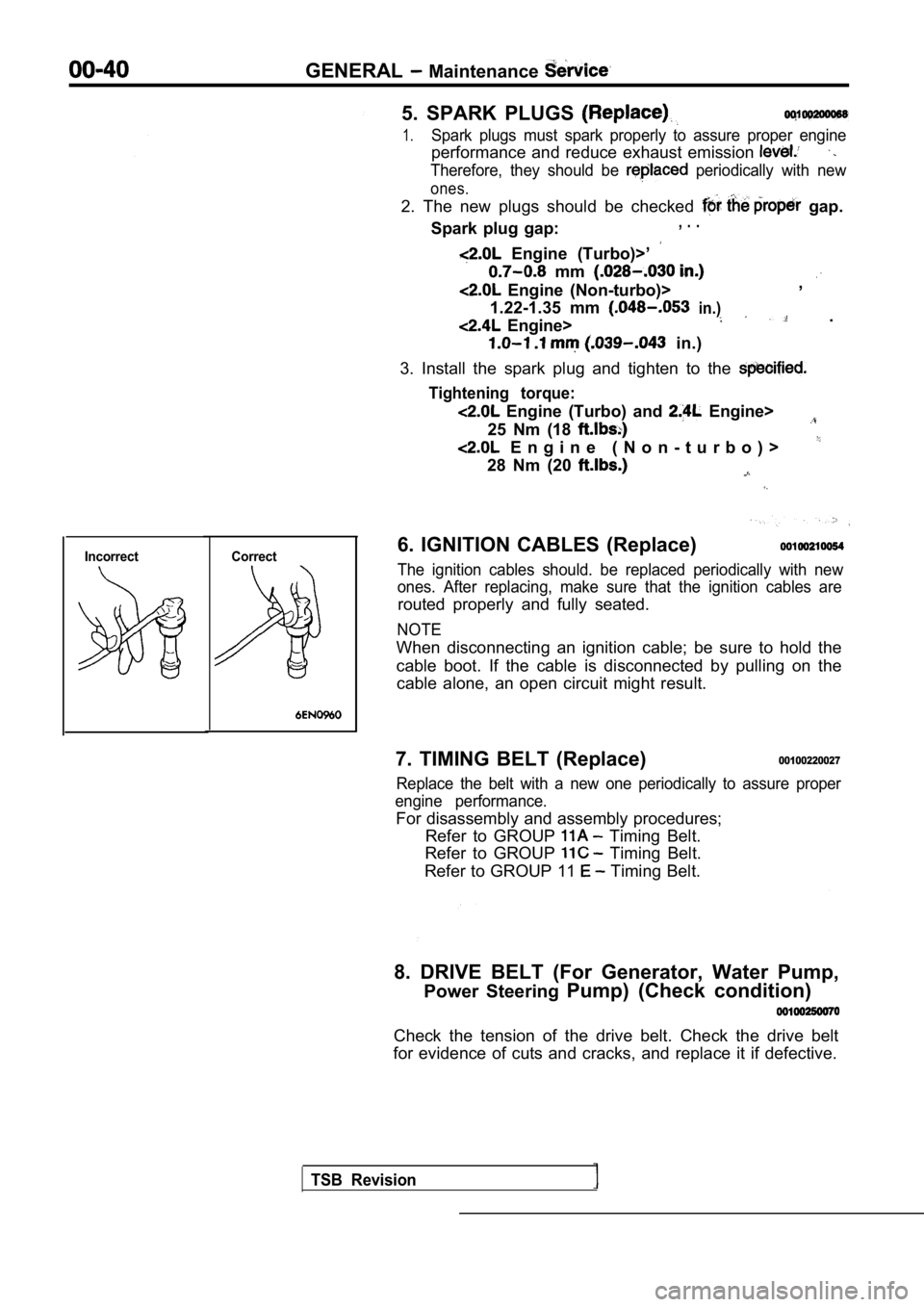
5. SPARK PLUGS
1.Spark plugs must spark properly to assure proper engine
performance and reduce exhaust emission
Therefore, they should be periodically with new
ones.
2. The new plugs should be checked gap.
Spark plug gap:, . .
Engine (Turbo)>’
mm
Engine (Non-turbo)> ,
1.22-1.35 mm
in.)
Engine> .
in.)
3. Install the spark plug and tighten to the
Tightening torque:
Engine (Turbo) and Engine>
25 Nm (18
E n g i n e ( N o n - t u r b o ) >
28 Nm (20
6. IGNITION CABLES (Replace)
The ignition cables should. be replaced periodicall y with new
ones. After replacing, make sure that the ignition cables are
routed properly and fully seated.
NOTE
When disconnecting an ignition cable; be sure to ho ld the
cable boot. If the cable is disconnected by pulling on the
cable alone, an open circuit might result.
7. TIMING BELT (Replace)
00100220027
Replace the belt with a new one periodically to ass ure proper
engine performance.
For disassembly and assembly procedures; Refer to GROUP
Timing Belt.
Refer to GROUP
Timing Belt.
Refer to GROUP 11
Timing Belt.
8. DRIVE BELT (For Generator, Water Pump, Power Steering Pump) (Check condition)
Check the tension of the drive belt. Check the driv e belt
for evidence of cuts and cracks, and replace it if defective.
TSB Revision
Page 43 of 2103
GENERAL Maintenance
Generator pulley
Crankshaft
Water pump
pump
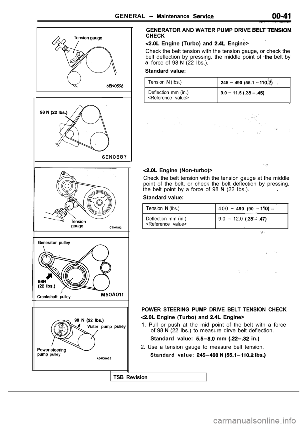
GENERATOR AND WATER PUMP DRIVE
CHECK
Engine (Turbo) and Engine>
Check the belt tension with the tension gauge, or c heck the
belt deflection by pressing. the middle point of
belt by
force of 98 (22 Ibs.).
Standard value:
Tension (Ibs.)
Deflection mm (in.)
9.0 11.5
,
Engine (Non-turbo)>
Check the belt tension with the tension gauge at th e middle
point of the belt, or check the belt deflection by pressing,
the belt point by a force of 98
(22 Ibs.). .
Standard value:
Tension (Ibs.)
Deflection mm (in.)
4 0 0 490 (90 --
9.0 12.0
POWER STEERING PUMP DRIVE BELT TENSION CHECK
Engine (Turbo) and Engine>
1. Pull or push at the mid point of the belt with a force
of 98
(22 Ibs.) to measure dirve belt deflection.
Standard value:
mm in.)
2. Use a tension gauge to measure belt tension. S t a n d a r d v a l u e :
TSB Revision
Page 92 of 2103
ENGINE Head Gasket’.
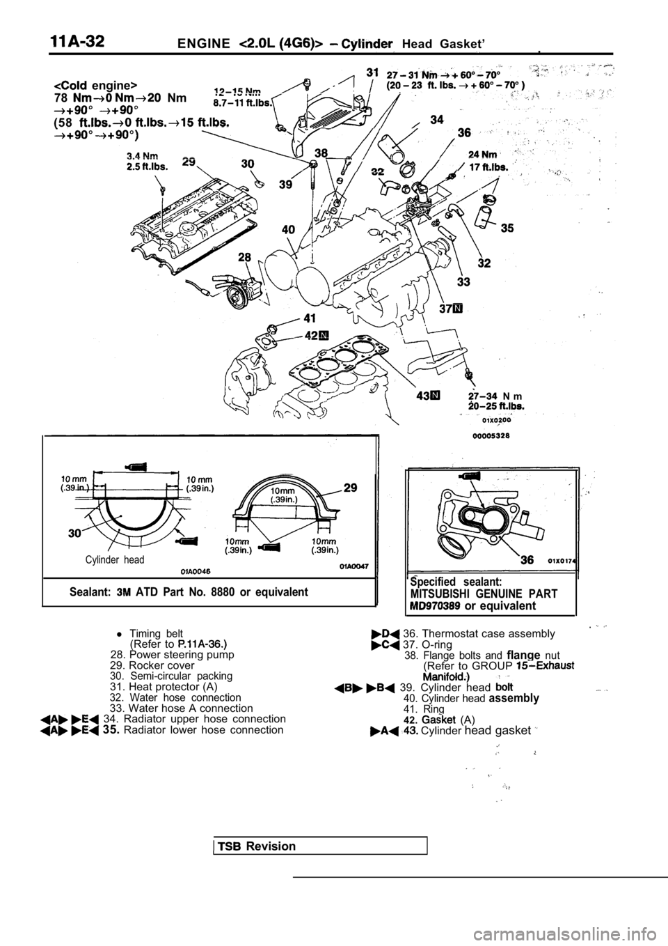
engine>
78
Nm
(58
N m
Cylinder head
Sealant: ATD Part No. 8880 or equivalent
Revision
Specified sealant: MITSUBISHI GENUINE PART
or equivalent
36. Thermostat case assembly 37. O-ring38. Flange bolts and flangenut(Refer to GROUP
39. Cylinder head 40. Cylinder head assembly41. Ring42. (A) Cylinder head gasket
l Timing belt(Refer to 28. Power steering pump
29. Rocker cover
30. Semi-circular packing31. Heat protector (A)32. Water hose connection33. Water hose A connection 34. Radiator upper hose connection 35. Radiator lower hose connection
Page 94 of 2103
ENGINE H e a d
I n t a k e s i d eFront of
enaine
Exhaust side
Step 4
I
Painted marks
Step 5
Painted marks
Thermostat case assembly orwater pump
Water inlet pipe assembly
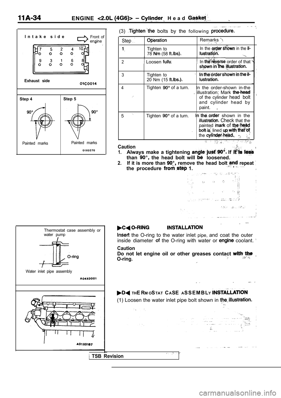
(3) bolts by the f o l l o w i n g
Step
Tighten to
78
(58
Remarks
In the in the
2 Loosen In order of that
3Tighten to
20 Nm (15
4Tighten of a turn.In the order-shown in-the
. illustration; Mark
of the cylinder head bolt
and cylinder head by
paint. ,
5
Tighten of a turn. shown in the
Check that the
painted
of
. lined
the
Caution
1.Always make a tightening If
than the head bolt will loosened.
2.If it is more than remove the head bolt repeat
the procedure 1. ,
the O-ring to the water inlet pipe,and coat the outer
inside diameter
the O-ring with water or coolant.
Caution
Do not let engine oil or other greases contact
O-ring.
TH E R M OSTAT CASE AS S E M B L Y
(1) Loosen the water inlet pipe bolt shown in
TSB Revision
Page 96 of 2103
E N G I N E Timing Belt
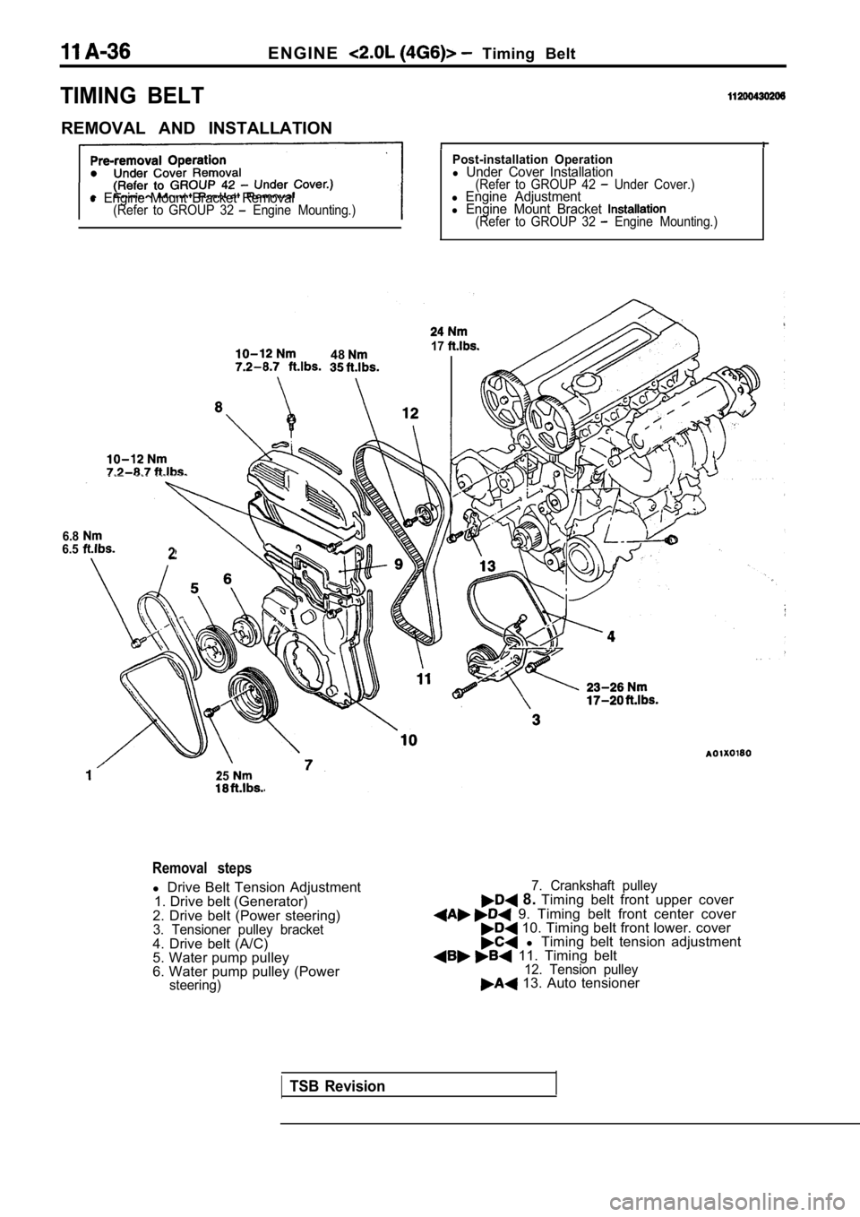
TIMING BELT
REMOVAL AND INSTALLATION
l Engine Mount Bracket Removal(Refer to GROUP 32 Engine Mounting.)
Post-installation Operationl Under Cover Installation(Refer to GROUP 42 Under Cover.)l Engine Adjustmentl Engine Mount Bracket (Refer to GROUP 32 Engine Mounting.)
4817
6.86.52
25
Removal steps
l Drive Belt Tension Adjustment
1. Drive belt (Generator)
2. Drive belt (Power steering)
3. Tensioner pulley bracket4. Drive belt (A/C)
5. Water pump pulley
6. Water pump pulley (Power
steering)
7. Crankshaft pulley 8. Timing belt front upper cover 9. Timing belt front center cover 10. Timing belt front lower. cover l Timing belt tension adjustment 11. Timing belt12. Tension pulley 13. Auto tensioner
TSB Revision
Page 97 of 2103
ENGINE Timing
(22-44
A
tensioner
marks Cylinder headI surface
I I I
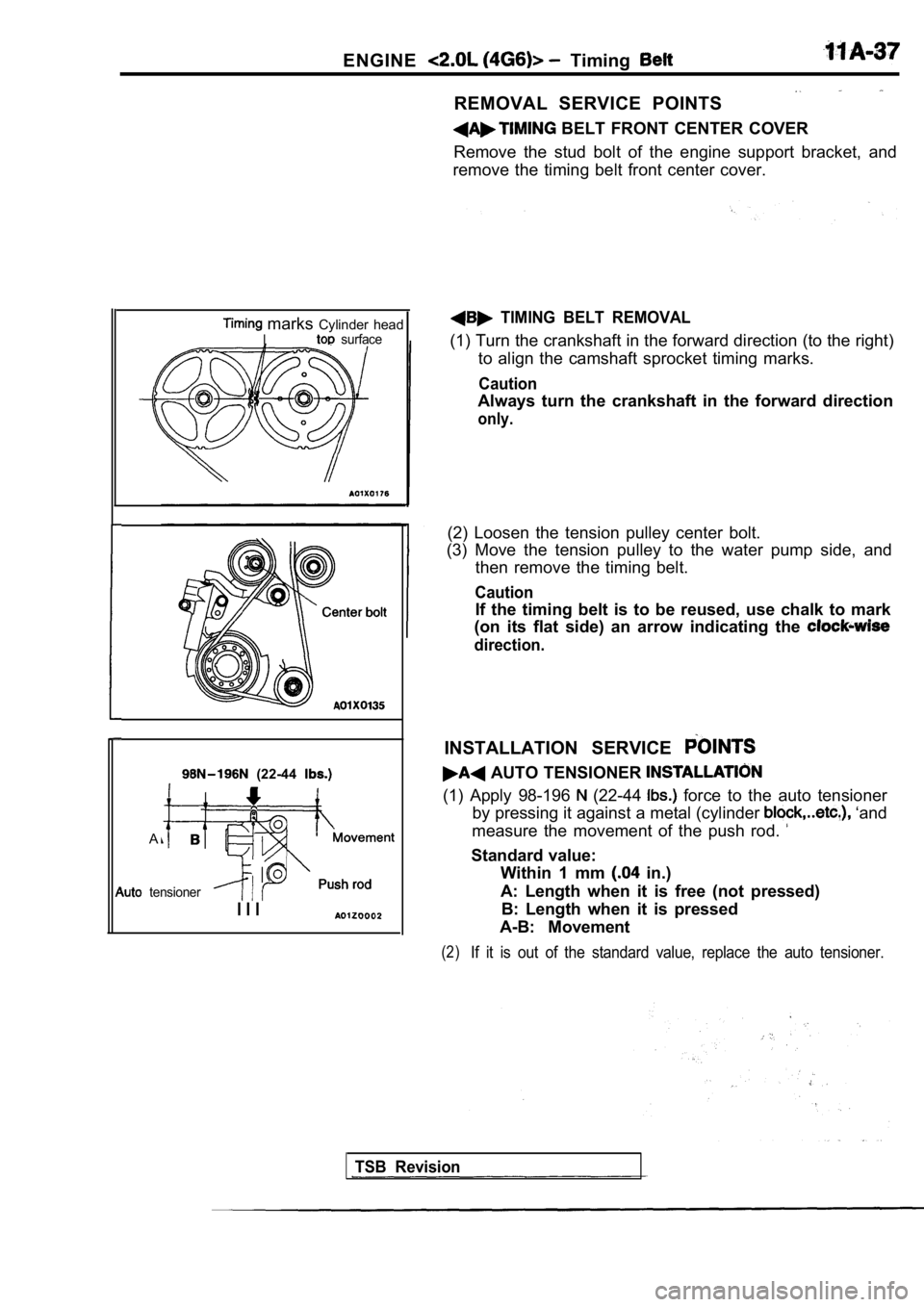
REMOVAL SERVICE POINTS
BELT FRONT CENTER COVER
Remove the stud bolt of the engine support bracket, and
remove the timing belt front center cover.
TIMING BELT REMOVAL
(1) Turn the crankshaft in the forward direction (t o the right)
to align the camshaft sprocket timing marks.
Caution
Always turn the crankshaft in the forward direction
only.
(2) Loosen the tension pulley center bolt.
(3) Move the tension pulley to the water pump side, and
then remove the timing belt.
Caution
If the timing belt is to be reused, use chalk to ma rk
(on its flat side) an arrow indicating the
direction.
INSTALLATION SERVICE
AUTO TENSIONER
(1) Apply 98-196 (22-44 force to the auto tensioner
by pressing it against a metal (cylinder
‘and
measure the movement of the push rod.
Standard value: Within 1 mm
in.)
A: Length when it is free (not pressed) B: Length when it is pressed
A-B: Movement
(2)If it is out of the standard value, replace the aut o tensioner.
TSB Revision
Page 105 of 2103
CONTENTS
BRACKET65
CRANKSHAFT, FLYWHEEL ANDDRIVE PLATE
. . . . . . . . . . . . . . . . . . . . . . . . . . . . .59
CYLINDER HEAD AND VALVES . . . . . . . . . . . 36
EXHAUST MANIFOLD AND
WATER PUMP. . . . . . . * . . . . . . . . . . . . . . . . . . . .29
FRONT CASE, COUNTERBALANCE
SHAFT AND OIL PAN . . . . . . . . . . . . . . . . . . . . . 42
FUEL AND EMISSION CONTROL
PARTS. . . . . . . . . . . . . . . . . . . . . . . . . . . . . . . . . . .25
GENERAL INFORMATION. . . . . . . . . . . . . . . . . .2
General Specifications . . . . . . . . . . . . . . . . . . , . . . . .2
GENERATOR IGNITION SYSTEM. . . . .11
INTAKE MANIFOLD. . . . . . . . . . . . . . . . . . . . . .
PISTON AND CONNECTING ROD..
. . . . . . . .51
ROCKER ARMS AND CAMSHAFT. . . . . . . .
SPECIAL TOOLS
. . . . . . . . . . . . . . . . . . . . . . . . . . .8
SPECIFICATIONS. . . . . . . . . . . . . . . . . . . . . . . . . .3
Rework Dimensions. . . . . . . . . . . . . . . . . . . . . . . . . .4
Sealant. . . . . . . . . . . . . . . . . . . . . . . . . . . . . . . . . .. . ..
Service Specifications. . . . . . . . . . . . . . . . . . . ....3
Torque Specifications. . . . . . . . . . . . . . . . . . . . . . . . . . . .5
TIMING BELT
. . . . . . . . . . . . . . . . . .. . . . . . . . .
,
Page 106 of 2103
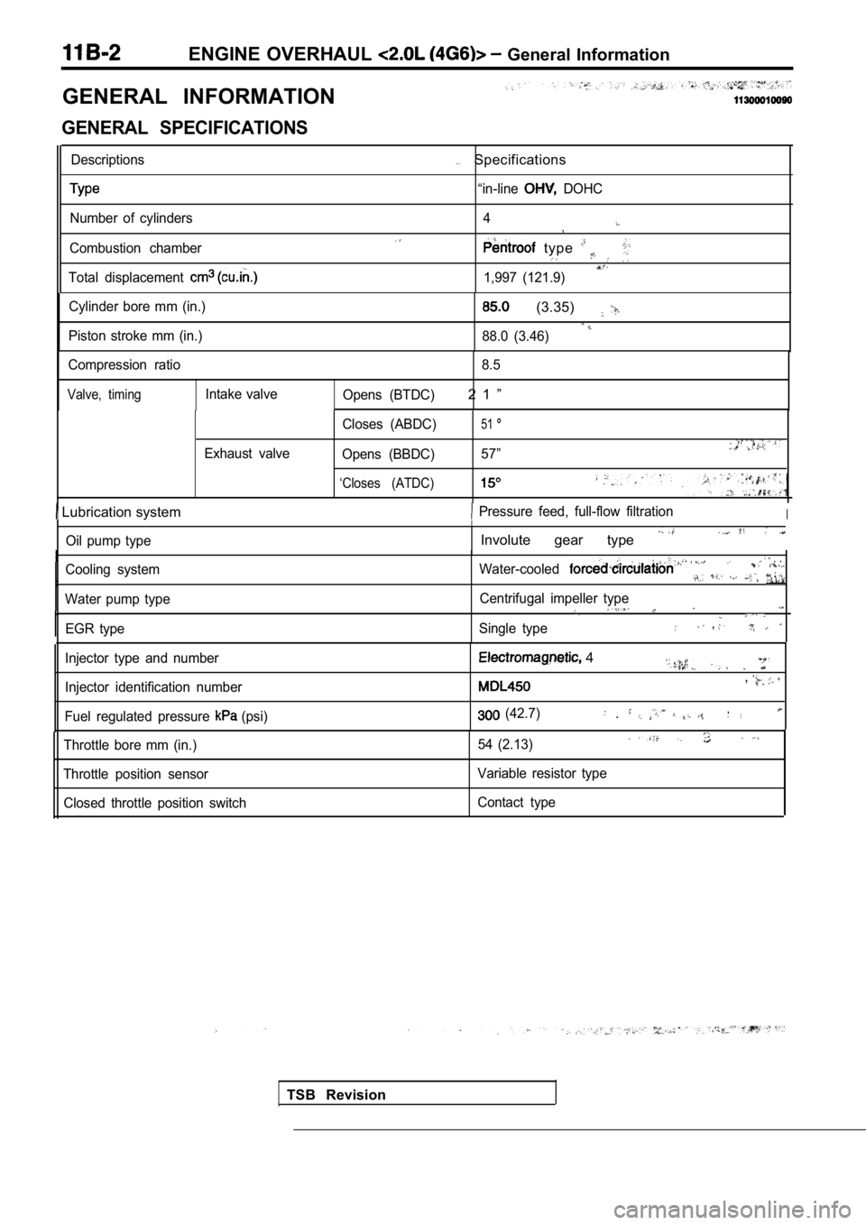
ENGINE OVERHAUL General Information
GENERAL INFORMATION
GENERAL SPECIFICATIONS
Descriptions
Number of cylinders
Combustion chamber
Total displacement
. . .Specifications
“in-line DOHC
4
type
1,997 (121.9)
Cylinder bore mm (in.)
Piston stroke mm (in.)
(3.35)
88.0 (3.46)
Compression ratio 8.5
Valve, timingIntake valve
Opens (BTDC)2 1 ”
Exhaust valve Closes (ABDC)
51
Opens (BBDC)
57”
‘Closes (ATDC)
Lubrication system Pressure feed, full-flow filtrationI
Oil pump type
Cooling system
Water pump type EGR type
I
Involute gear type
Water-cooled . .
Centrifugal impeller type
Single type,
TSB Revision
Injector type and number
Injector identification number
Fuel regulated pressure
(psi)
4
,
(42.7) .
Throttle bore mm (in.)
Throttle position sensor Closed throttle position switch 54 (2.13)
Variable resistor type
Contact type
Page 115 of 2103
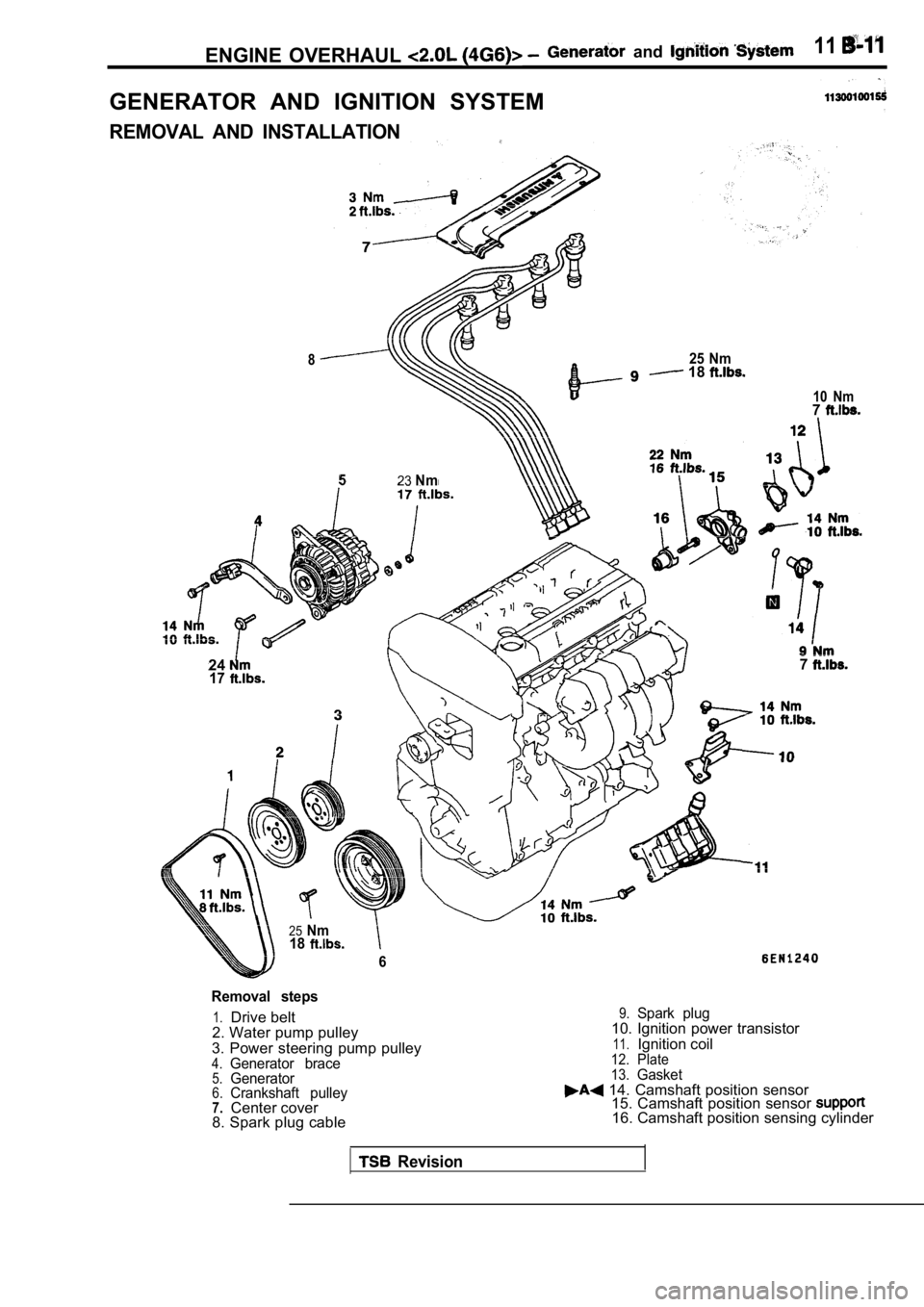
ENGINE OVERHAUL and 11
GENERATOR AND IGNITION SYSTEM
REMOVAL AND INSTALLATION
825 Nm 18
523Nm
24177
25Nm18
6
10 Nm7
Removal steps
1.Drive belt
2. Water pump pulley
3. Power steering pump pulley
4.Generator brace5.Generator6.Crankshaft pulley7.Center cover
8. Spark plug cable
9.Spark plug10. Ignition power transistor
11.Ignition coil12. Plate
13.Gasket 14. Camshaft position sensor 15. Camshaft position sensor
16. Camshaft position sensing cylinder
Revision