ECU MITSUBISHI TRITON 1997 Manual Online
[x] Cancel search | Manufacturer: MITSUBISHI, Model Year: 1997, Model line: TRITON, Model: MITSUBISHI TRITON 1997Pages: 1310, PDF Size: 22.38 MB
Page 978 of 1310
2
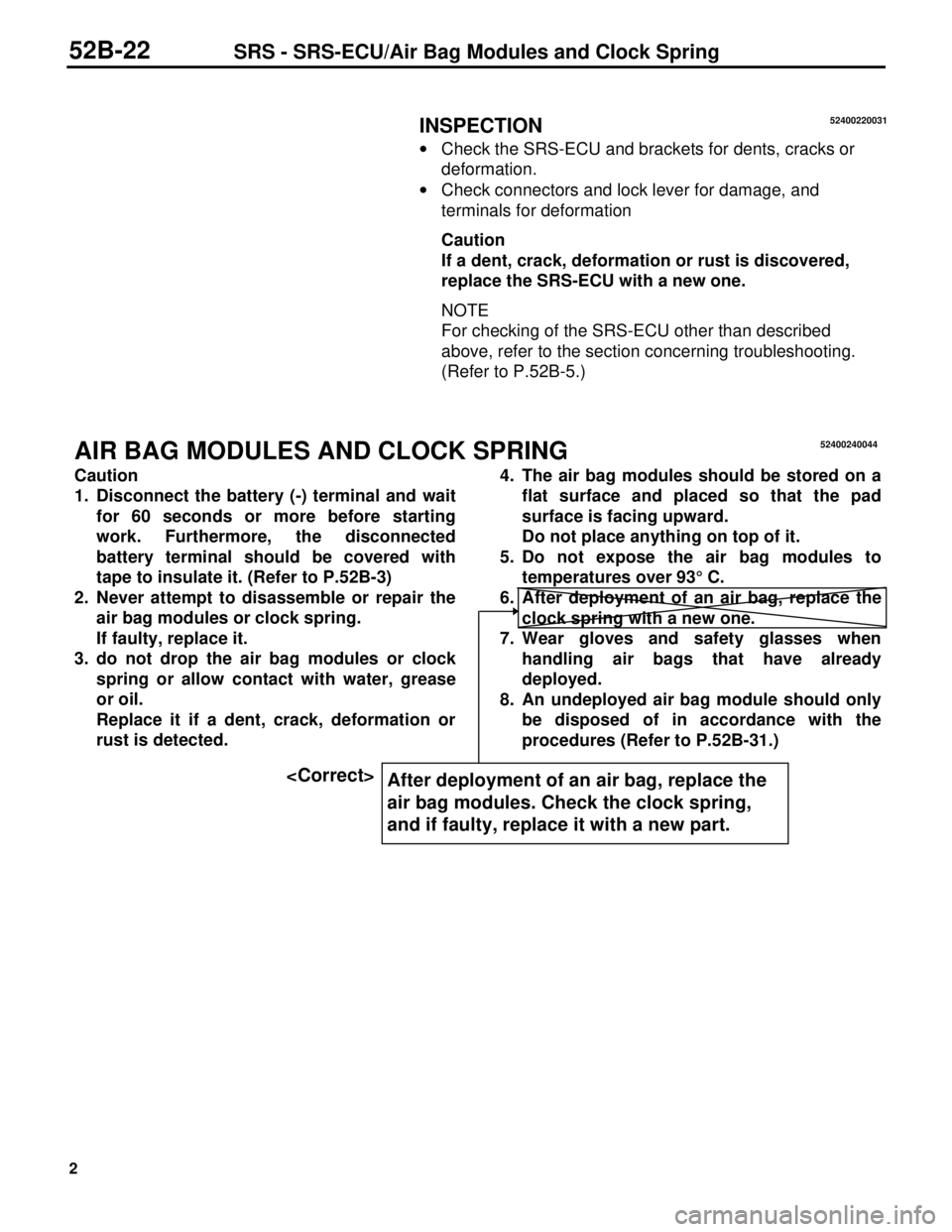
INSPECTION
· Check the SRS-ECU and brackets for dents, cracks or
deformation.
· Check connectors and lock lever for damage, and
terminals for deformation
Caution
If a dent, crack, deformation or rust is discovered,
replace the SRS-ECU with a new one.
NOTE
For checking of the SRS-ECU other than described
above, refer to the section concerning troubleshooting.
(Refer to P.52B-5.)
AIR BAG MODULES AND CLOCK SPRING
Caution
1. Disconnect the battery (-) terminal and wait
for 60 seconds or more before starting
work. Furthermore, the disconnected
battery terminal should be covered with
tape to insulate it. (Refer to P.52B-3)
2. Never attempt to disassemble or repair the
air bag modules or clock spring.
If faulty, replace it.
3. do not drop the air bag modules or clock
spring or allow contact with water, grease
or oil.
Replace it if a dent, crack, deformation or
rust is detected.4. The air bag modules should be stored on a
flat surface and placed so that the pad
surface is facing upward.
Do not place anything on top of it.
5. Do not expose the air bag modules to
temperatures over 93° C.
6. After deployment of an air bag, replace the
clock spring with a new one.
7. Wear gloves and safety glasses when
handling air bags that have already
deployed.
8. An undeployed air bag module should only
be disposed of in accordance with the
procedures (Refer to P.52B-31.)
52B-22SRS - SRS-ECU/Air Bag Modules and Clock Spring
52400220031
After deployment of an air bag, replace the
air bag modules. Check the clock spring,
and if faulty, replace it with a new part.
52400240044
Page 990 of 1310

10
2.
Exit conditions from the adjustment mode
The ETACS-ECU cancels the adjustment mode when any of the following conditions is satisfied:
•
Diagnosis control: OFF (Disconnect the MUT-II>)
•
Key reminder switch: ON (Pull out the ignition key.)
•
Ignition switch: Other than LOCK (OFF)
•
Door switch: ON (Open the door)
•
After the ETACS_ECU has entered the adjustment mode, no adjustment is made within 3 minutes (If
any adjustment is made within 3 minutes, the ETACS-ECU monitors an adjustment operation for
other 3 minutes.
•
Other warning buzzer(s) sounds
3.
Adjustment of functions
Function Adjustment procedure
Keyless entry answerback function When the transmitter lock switch is turned on twice continuously
within 2 seconds, the lock answerback function toggles on and off.
•
If the function toggles on, the buzzer sounds once (default con-
dition).
•
If the function toggles off, the buzzer sounds twice,
When the transmitter unlock switch is turned on twice continuously
within 2 seconds, the unlock answerback function toggles on and
off.
•
If the function toggles on, the buzzer sounds once (default con-
dition).
•
If the function toggles off, the buzzer sounds twice,
Initialisation of all the ETACS func-
tions (From deactivation to activa-
tion)When the tailgate switch remains on for more than 20 seconds, th
buzzer sounds twice and he answer-back function of the keyless
entry system is initialised.
The buzzer will sound in 10 seconds (indicating that the ETACS-
ECU enters the adjustment mode), but the washer switch must re-
mains off for 20 seconds in order to initialise all the functions.
If the tailgate switch remains on for more than 20 seconds without
entering the adjustment mode, the system enters the adjustment
mode in 10 seconds, but does not initialise all of the functions.
INSPECTION CHART FOR TROUBLE SYMPTOMS
Trouble symptom Inspection procedure No. Reference page
None of the doors can be locked or unlocked using th
transmitter.142-3
All of the doors can be locked and unlocked using th
transmitter, but the room lamp or turn-signal lamp does
not flash or illuminate. (However, the room lamp oper-
ates normally when the doors are opened and closed.)242-4
Encrypted codes cannot be registered. 3 42-5
42-2BODY – Keyless entry system
Page 991 of 1310

11
INSPECTION PROCEDURE FOR TROUBLE SYMPTOMS
INSPECTION PROCEDURE 1
None of the doors can be locked or unlocked using
the transmitter.Probable cause
The cause may be a malfunction of the transmitter or ETACS-
ECU, defective connection between ETACS-ECU and junction
block, defective power supply voltage to ETACS-ECU input
line due to commercial equipment, or the lock and unlock sig-
nals are not being sent to the ETACS-ECU.•
Malfunction of transmitter
•
Malfunction of ETACS-ECU
•
Malfunction of key reminder switch
•
Malfunction of wiring harness or connector
•
Malfunction of door switch
•
Defective connection between ETACS-ECU and
junction block
•
Defective power supply voltage to ETACS-ECU
input line due to commercial equipment
Check the central door lock systemCan the doors be locked and unlocked by the pas-
senger’s-side door key cylinder and lock knob?
YesNo
Has the encrypted code been registered properly? * NG Re-register the encrypted code. (Refer to P.42.6)
OK
Replace the transmitter battery. (Refer to P.42-6)
NG
Is a commercial equipment equipped?
NoYes
Remove that equipment, and then check trouble
symptoms.
NG
Check the connection between ETACS-ECU and
junction block claw.NG
Repair
OK
NG .Check the following connectors:
A-56X, C-81, C-91
OK NG
Measure at the ETACS-ECU connector C-91.
•
Disconnect the connector, and measure at the
harness side.
•
Voltage between 2 and body earth
OK:
System voltageCheck trouble symptomsRepair
OK NG
Check the harness wire, and repair if necessary.
•
Between fusible link No.5 and ETACS-ECU
Door switch continuity check
OK NG
Mut-II Pulse Check
•
Door switch input signal
OK:
MUT-II Buzzer sounds once when opening
and closing each door.NG
Repair
OK
Check the following connectors:
C-110, D-03, D-07, D-14, D-17, D-21
OK NG
Check trouble Symptoms.Repair
NG
To next pageCheck the harness wire, and repair if necessary.
•
Between ETACS-ECU and door switch
NOTE
*: This should be done if a transmitter, receiver or ETACS-ECU has been replaced, and if a secret cod
has not been registered properly
BODY – Keyless Entry System42-3
Page 992 of 1310

12From previous page
Key reminder switch continuity check
OK NG
MUT-II Pulse Check
•
Key reminder switch input signal
OK:
MUT-II buzzer sounds once when removing
and inserting ignition key.NG
Repair
OK
Check the following connectors:
C-72, C-79, C-86, C-91
Replace the transmitter.OK NG
OK
Check trouble symptomsRepair
Check the trouble symptoms.NG
OK
Replace the ETACS-ECU.
Check the harness wire, and repair if necessary.
•
Between key reminder switch and ETACS-ECU
•
Between key reminder switch and earth
INSPECTION PROCEDURE 2
All of the doors can be locked and unlocked using th
transmitter, but the room lamp or turn-signal lamp does
not flash or illuminate. (However, the room lamp oper-
ates normally when the doors are opened and closed.)Probable cause
If neither room lamp nor turn-signal lamp flash/illuminate, the
cause may be a malfunction of the ETACS-ECU or driver’s-side
door lock actuator.
If either room lamp or turn-signal lamp does not flash/illuminate,
the cause may be a malfunction of the room lamp circuit or turn-
signal lamp.•
Malfunction of ETACS-ECU
•
Malfunction of driver’s door lock actuator
•
Burnt turn-signal lamp bulb
•
Malfunction of connector or wiring harness
Carry out the troubleshooting for room lamp circuit.Does the room lamp go on/go off simultaneous
with opening/closing door?NO
Yes
Does the turn-signal lamp flash when the turn-
signal lamp switch is operated?NO
Carry out the troubleshooting for turn-signal lamp
circuit.
Yes
NG
Check the driver’s door lock actuator
OK NG
MUT-II Pulse Check
•
Drivers door lock actuator switch input signal
OK:
MUT-II buzzer sounds once when locking
or unlocking driver’s door.Replace
OKCheck the following connectors:
C-38, C-110, E-09
E-20
Replace the ETACS-ECUOK NG
Check trouble symptoms.Repair
NG
Check the harness wire, and repair if necessary.
•
Between ETACS-ECU and driver’s door lock actua-
tor
•
Between driver’s door lock actuator and earth
42-4BODY – Keyless Entry System
Page 993 of 1310

13
INSPECTION PROCEDURE 3
Encrypted codes cannot be registered Probable cause
The cause may be a malfunction of the diagnosis con-
nector, ETACS-ECU or diagnosis output circuit.•
Malfunction of MUT-II
•
Malfunction of connector or wiring harness
•
Malfunction of ETACS-ECU
NGCheck the following connectors:
C-35, D-110
OK NG
Check trouble symptomsRepair
NG
Measure at diagnosis connector C-35 and ETACS-
ECU connector D-110.
•
Disconnect the connector, and measure at har
ness side.
•
Continuity between following terminals:
OK:
Continuity
28
•
Between the ETACS-ECU and diagnosis connector
OK
Can the MUT-II communicate with other systems?
Yes No
NGCheck the following connectors:
A-56X, C-35, C-79, C-81
OK NG
Check trouble symptoms.Repair
Measure at the diagnosis
connector C-35
•
Voltage between 16
and body earth
OK:
System voltage
NG
OKCheck the harness wire, and repair if necessary.
•
Between fusible link No.5 and diagnosis connector
OK
Replace MUT-II.Measure at the diagnosis
connector C-35.
•
Continuity between 4
and body earth
•
Continuity between 5
and body earth
OK:
System voltage
NG
NG
RepairCheck the following
connectors:
C-35, C-86
OK
Check trouble symptoms.NG
Check the harness wire, and repair if necessary.
•
Between the diagnosis connector and earth
NG
Check the following connectors:
A-56X, C-81, C-82, C-88, C-91
OK NG
Check trouble symptomsRepair
NG
Measure at the ETACS-ECU connector C-91.
•
Disconnect the connector, and measure at the
harness side
•
Voltage between 1 and body earth
•
Voltage between 2 and body earth
•
Voltage between 3 and body earth
OK:
System voltage
OKCheck the harness wire, and repair if necessary.
•
Between dedicated fuse No.6 and ETACS-ECU
•
Between ignition switch (IG1) and ETACS-ECU
Check the following connectors:
C-86, C-91
OK NG
Check trouble symptoms.
Repair
Measure at the ETACS-ECU connectors C-91
•
Disconnect the connector, and measure at the
harness side.
•
Between 10 for connector C-91 and body earth
OK:
System voltage
NG
OK
Replace the ETACS-ECU.Check the harness wire, and repair if necessary.
•
Between the ETACS-ECU and earth
BODY – Keyless Entry System42-5
Page 1001 of 1310

2
Manual Pub. No. Language Page(s)
’97 L200PWTE96E1(English) 35b-5
Workshop Manual Chassis PWTS96E1 (Spanish)
PWTF96E1 (French)
PWTG96E1 (German)
2000 L200PWTE96E2(English) 35b-5
Workshop Manual Chassis PWTS96E2 (Spanish)
PWTF96E2 (French)
PWTG96E2 (German)
3. Effective date:
Model Effective Date ABS-ECU part No.
COLT/LANCER From March 1998 MR445910
PAJERO/MONTERO From September 1998 MR400413
L400 From September 1998 MR400415
PAJERO SPORT/
MONTERO SPORTFrom the first production car MR235362*, MR307755*,
MR334886*
L200 From September 1998 MR400416, MR400417,
MR4469642*
* Integral Hydraulic unit. These part numbers are for the hydraulic unit.
4. Details:
’96 COLT/LANCER Workshop Manual Chassis (page 3.)
’95 PAJERO Workshop Manual Chassis Supplement (page 5.)
’95 L400 Workshop Manual Chassis (page 7.)
’99 PAJERO SPORT Workshop Manual Chassis (page 9.)
’97 L200 Workshop Manual (page 11.)
’00 L200 Workshop Manual (page 13.)
Page 1031 of 1310
10
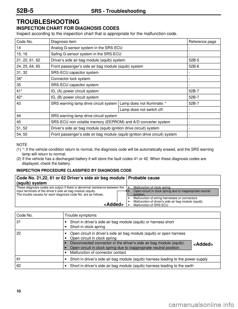
TROUBLESHOOTING
INSPECTION CHART FOR DIAGNOSIS CODES
Inspect according to the inspection chart that is appropriate for the malfunction code.
Code No. Diagnosis item Reference page
14 Analog G-sensor system in the SRS-ECU -
15, 16 Safing G-sensor system in the SRS-ECU -
21, 22, 61, 62 Driver’s side air bag module (squib) system 52B-5
24, 25, 64, 65 Front passenger’s side air bag module (squib) system 52B-6
31, 32 SRS-ECU capacitor system -
34* Connector lock system -
35 SRS-ECU capacitor system -
41* IG1 (A) power circuit system 52B-7
42* IG1 (B) power circuit system 52B-7
43 SRS warning lamp drive circuit system Lamp does not illuminate. * 52B-7
Lamp does not switch off. -
44 SRS warning lamp drive circuit system -
45 SRS-ECU non volatile memory (EEPROM) and A/D converter system -
51, 52 Driver’s side air bag module (squib ignition drive circuit) system -
54, 55 Front passenger’s side sir bag module (squib ignition drive circuit) system -
NOTE
(1) *: if the vehicle condition return to normal, the diagnosis code will be automatically erased, and the SRS warning
lamp will return to normal.
(2) If the vehicle has a discharged battery it will store the fault codes 41 or 42. When these diagnosis codes are
displayed, check the battery.
INSPECTION PROCEDURE CLASSIFIED BY DIAGNOSIS CODE
Code No. 21,22, 61 or 62 Driver’s side air bag module
(squib) systemProbable cause
These diagnosis codes are output if there is abnormal resistance between the
input terminals of the driver’s side air bag module (squib).
The trouble causes for each diagnosis code No. are as follows.·
Malfunction of clock spring
·
Open-circuit in clock spring due to inappropriate neutral
position.
·
Malfunction of wiring harnesses or connectors
·
Malfunction of driver’s side air bag module (squib)
·
Malfunction of SRS-ECU
Code No. Trouble symptoms
21
·
Short in driver’s side air bag module (squib) or harness short
·
Short in clock spring
22
·
Open circuit in driver’s side air bag module (squib) or open harness
·
Open circuit in clock spring
·
Disconnected connector in the driver’s side air bag module (squib).
·
Open circuit in clock spring due to inappropriate neutral position.
·
Malfunction of connector contact
61
·
Short in driver’s side air bag module (squib) harness leading to the power supply
62
·
Short in driver’s side air bag module (squib) harness leading to the earth
52B-5SRS - Troubleshooting
Page 1036 of 1310
15
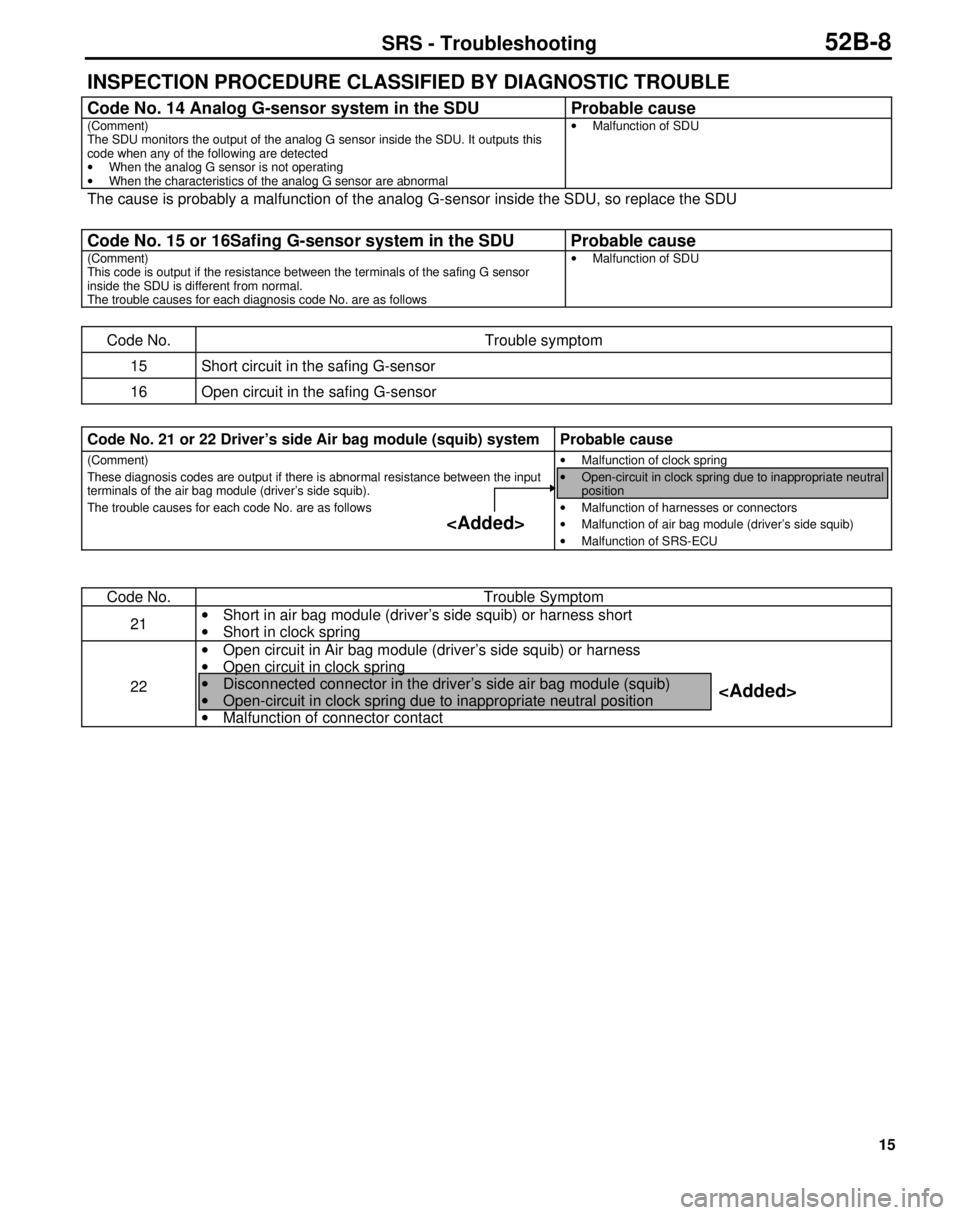
INSPECTION PROCEDURE CLASSIFIED BY DIAGNOSTIC TROUBLE
Code No. 14 Analog G-sensor system in the SDU Probable cause
(Comment)
The SDU monitors the output of the analog G sensor inside the SDU. It outputs this
code when any of the following are detected
·
When the analog G sensor is not operating
·
When the characteristics of the analog G sensor are abnormal·
Malfunction of SDU
The cause is probably a malfunction of the analog G-sensor inside the SDU, so replace the SDU
Code No. 15 or 16Safing G-sensor system in the SDU Probable cause
(Comment)
This code is output if the resistance between the terminals of the safing G sensor
inside the SDU is different from normal.
The trouble causes for each diagnosis code No. are as follows·
Malfunction of SDU
Code No. Trouble symptom
15 Short circuit in the safing G-sensor
16 Open circuit in the safing G-sensor
Code No. 21 or 22 Driver’s side Air bag module (squib) system Probable cause
(Comment)
These diagnosis codes are output if there is abnormal resistance between the input
terminals of the air bag module (driver’s side squib).
The trouble causes for each code No. are as follows·
Malfunction of clock spring
·
Open-circuit in clock spring due to inappropriate neutral
position
·
Malfunction of harnesses or connectors
·
Malfunction of air bag module (driver’s side squib)
·
Malfunction of SRS-ECU
Code No. Trouble Symptom
21·
Short in air bag module (driver’s side squib) or harness short
·
Short in clock spring
22·
Open circuit in Air bag module (driver’s side squib) or harness
·
Open circuit in clock spring
·
Disconnected connector in the driver’s side air bag module (squib)
·
Open-circuit in clock spring due to inappropriate neutral position
·
Malfunction of connector contact
SRS - Troubleshooting52B-8
Page 1042 of 1310
21
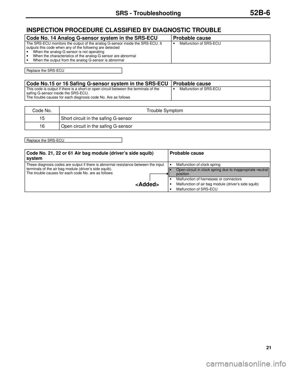
INSPECTION PROCEDURE CLASSIFIED BY DIAGNOSTIC TROUBLE
Code No. 14 Analog G-sensor system in the SRS-ECU Probable cause
The SRS-ECU monitors the output of the analog G-sensor inside the SRS-ECU. It
outputs this code when any of the following are detected
·
When the analog-G sensor is not operating
·
When the characteristics of the analog-G sensor are abnormal
·
When the output from the analog G-sensor is abnormal·
Malfunction of SRS-ECU
Replace the SRS-ECU
Code No.15 or 16 Safing G-sensor system in the SRS-ECU Probable cause
This code is output if there is a short or open circuit between the terminals of the
safing G-sensor inside the SRS-ECU.
The trouble causes for each diagnosis code No. Are as follows·
Malfunction of SRS-ECU
Code No. Trouble Symptom
15 Short circuit in the safing G-sensor
16 Open circuit in the safing G-sensor
Replace the SRS-ECU
Code No. 21, 22 or 61 Air bag module (driver’s side squib)
systemProbable cause
These diagnosis codes are output if there is abnormal resistance between the input
terminals of the air bag module (driver’s side squib).
The trouble causes for each code No. are as follows·
Malfunction of clock spring
·
Open-circuit in clock spring due to inappropriate neutral
position
·
Malfunction of harnesses or connectors
·
Malfunction of air bag module (driver’s side squib)
·
Malfunction of SRS-ECU
SRS - Troubleshooting52B-6
Page 1064 of 1310
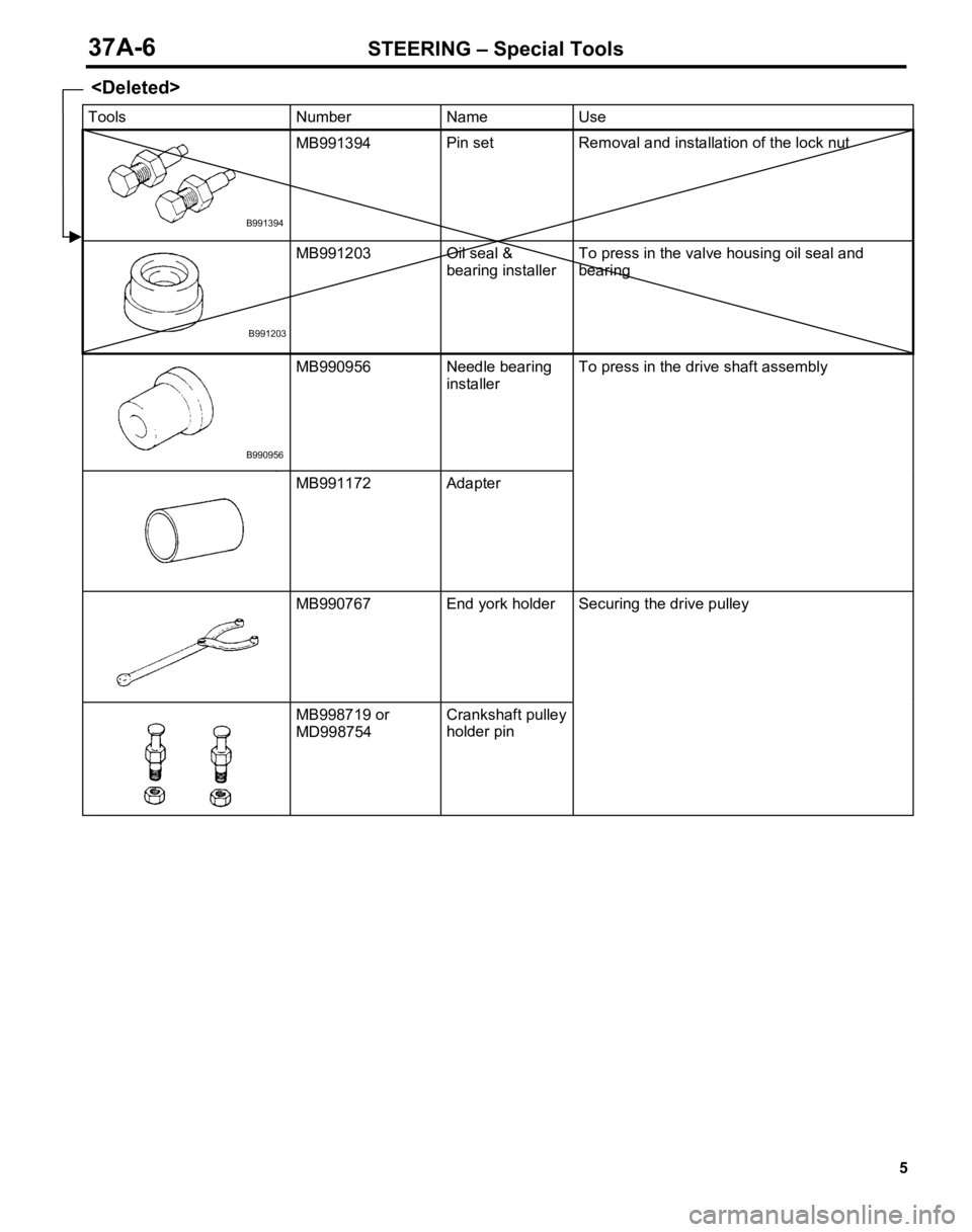
M
B9913 94 P
in s e t Rem ova l a nd in sta ll a tio n o f th e lo ck n ut M
B9912 03 O
il s e a l &
b earin g in sta ll e r T
o p re ss in th e v a lv e h ousin g o il s e a l a n d
b earin g M
B9909 56 Need le b earin g
i n sta lle r M
B9911 72 A
da pte r T
o p re ss in th e d riv e s h aft a sse m bly M
B9907 67 E
nd y o rk h old er M
B9987 19 o r
M D99 875 4 C
ra nksh aft p ulle y
h old er p in S
ecu rin g t h e d riv e p ulle y