GENERAL ± How to Use This Manual00-2
HOW TO USE THIS MANUAL00100010210
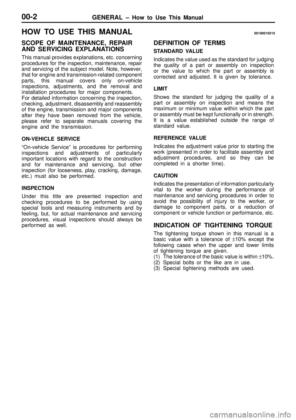
SCOPE OF MAINTENANCE, REPAIR
AND SERVICING EXPLANATIONS
This manual provides explanations, etc. concerning
procedures for the inspection, maintenance, repair
and servicing of the subject model. Note, however,
that for engine and transmission-related component
parts, this manual covers only on-vehicle
inspections, adjustments, and the removal and
installation procedures for major components.
For detailed information concerning the inspection,
checking, adjustment, disassembly and reassembly
of the engine, transmission and major components
after they have been removed from the vehicle,
please refer to separate manuals covering the
engine and the transmission.
ON-VEHICLE SERVICE
ªOn-vehicle Serviceº is procedures for performing
inspections and adjustments of particularly
important locations with regard to the construction
and for maintenance and servicing, but other
inspection (for looseness, play, cracking, damage,
etc.) must also be performed.
INSPECTION
Under this title are presented inspection and
checking procedures to be performed by using
special tools and measuring instruments and by
feeling, but, for actual maintenance and servicing
procedures, visual inspections should always be
performed as well.
DEFINITION OF TERMS
STANDARD VALUE
Indicates the value used as the standard for judging
the quality of a part or assembly on inspection
or the value to which the part or assembly is
corrected and adjusted. It is given by tolerance.
LIMIT
Shows the standard for judging the quality of a
part or assembly on inspection and means the
maximum or minimum value within which the part
or assembly must be kept functionally or in strength.
It is a value established outside the range of
standard value.
REFERENCE VALUE
Indicates the adjustment value prior to starting the
work (presented in order to facilitate assembly and
adjustment procedures, and so they can be
completed in a shorter time).
CAUTION
Indicates the presentation of information particularly
vital to the worker during the performance of
maintenance and servicing procedures in order to
avoid the possibility of injury to the worker, or
damage to component parts, or a reduction of
component or vehicle function or performance, etc.
INDICATION OF TIGHTENING TORQUE
The tightening torque shown in this manual is a
basic value with a tolerance of +10% except the
following cases when the upper and lower limits
of tightening torque are given.
(1) The tolerance of the basic value is within +10%.
(2) Special bolts or the like are in use.
(3) Special tightening methods are used.
GENERAL ± How to Use This Manual00-3
MODEL INDICATIONS
The following abbreviations are used in this manual for classification of model types.
M/T: Indicates the manual transmission, or models equipped with the manual transmission.
A/T: Indicates the automatic transmission, or models equipped with the automatic transmission.
SOHC: Indicates an engine with the single overhead camshaft, or a model equipped with such
an engine.
MPI: Indicates the multi-point injection, or engines equipped with the multi-point injection.
DIESEL: Indicates a diesel engine, or models equipped with such an engine.
2WD: Indicates the rear wheel-drive vehicles.
4WD: Indicates the 4 wheel-drive vehicles.
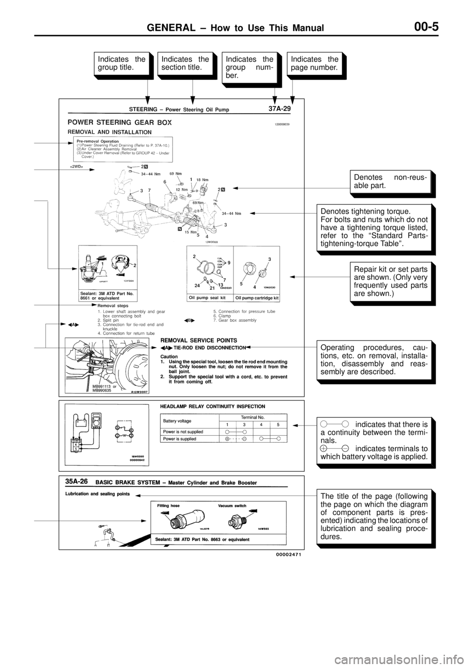
i
n dic a te s th at th ere is
a c o ntin uit y b etw een th e te rm i-
n als .
in dic a te s te rm in als to
w hic h b atte ry v o lt a ge is a pplie d. I
n dic a te s th e
s e ctio n tit le . I
n dic a te s th e
g ro up n um -
b er. I
n dic a te s th e
p age n um ber. I
n dic a te s th e
g ro up tit le . D
enote s n on-re us-
a ble p art. R
epair k it o r s e t p arts
a re s h ow n. ( O nly v e ry
f r e quently u se d p arts
a re s h ow n.) O
pera tin g p ro ce dure s, c a u-
t io ns, e tc . o n r e m ova l, in sta lla -
t io n, d is a sse m bly a nd r e as-
s e m bly a re d escrib ed. T
he tit le o f th e p age ( fo llo w in g
t h e p age o n w hic h th e d ia gra m
o f c o m ponent p arts is p re s-
e nte d) in dic a tin g th e lo ca tio ns o f
l u bric a tio n a nd s e alin g p ro ce -
d ure s.
GENERAL ± How to Use Troubleshooting/Inspection Service Points00-6
HOW TO USE TROUBLESHOOTING/INSPECTION SERVICE
POINTS
00100020091
Troubleshooting of electronic control systems for which the MUT-II can be used follows the basic outline
described below. Furthermore, even in systems for which the MUT-II cannot be used, part of these systems
still follow this outline.
TROUBLESHOOTING CONTENTS
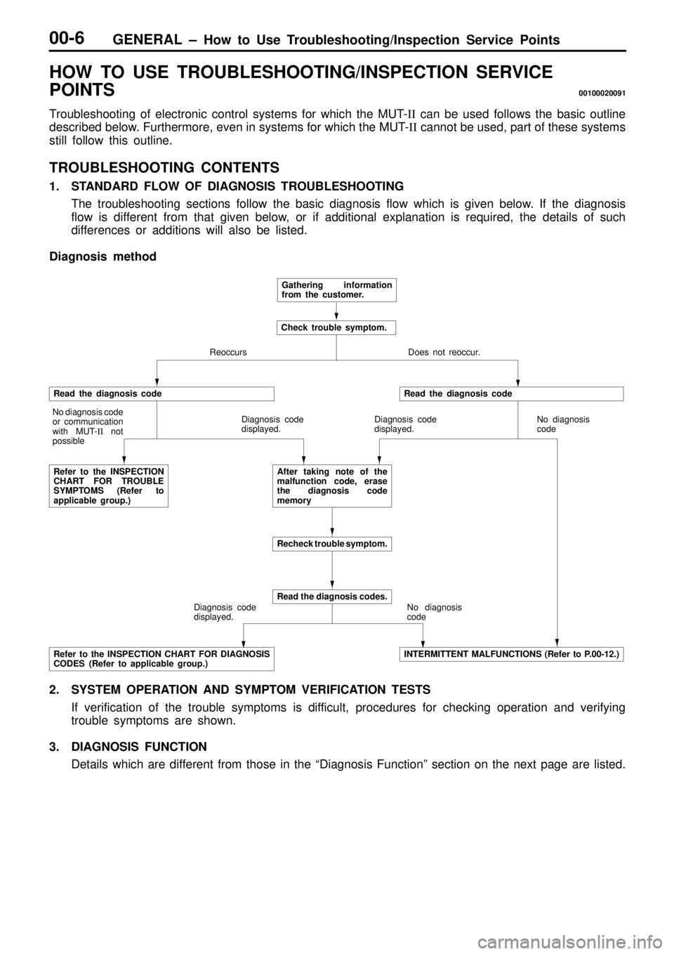
1. STANDARD FLOW OF DIAGNOSIS TROUBLESHOOTING
The troubleshooting sections follow the basic diagnosis flow which is given below. If the diagnosis
flow is different from that given below, or if additional explanation is required, the details of such
differences or additions will also be listed.
Diagnosis method
Gathering information
from the customer.
Check trouble symptom.
Reoccurs Does not reoccur.
Read the diagnosis code
No diagnosis code
or communication
with MUT-II not
possible
Refer to the INSPECTION
CHART FOR TROUBLE
SYMPTOMS (Refer to
applicable group.)Diagnosis code
displayed.
Read the diagnosis code
Diagnosis code
displayed.No diagnosis
code
After taking note of the
malfunction code, erase
the diagnosis code
memory
Recheck trouble symptom.
Diagnosis code
displayed.
Read the diagnosis codes.
No diagnosis
code
Refer to the INSPECTION CHART FOR DIAGNOSIS
CODES (Refer to applicable group.)INTERMITTENT MALFUNCTIONS (Refer to P.00-12.)
2. SYSTEM OPERATION AND SYMPTOM VERIFICATION TESTS
If verification of the trouble symptoms is difficult, procedures for checking operation and verifying
trouble symptoms are shown.
3. DIAGNOSIS FUNCTION
Details which are different from those in the ªDiagnosis Functionº section on the next page are listed.
