WW-4
FRONT WIPER AND WASHER SYSTEM
Revision: 2006 November2007 350Z
FRONT WIPER AND WASHER SYSTEMPFP:28810
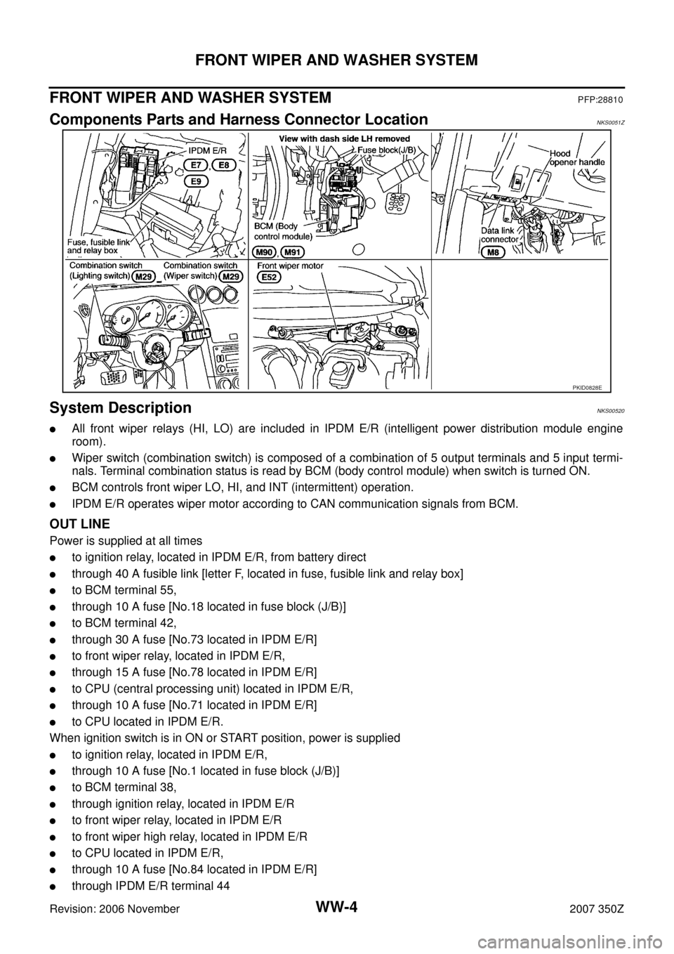
Components Parts and Harness Connector LocationNKS0051Z
System DescriptionNKS00520
�All front wiper relays (HI, LO) are included in IPDM E/R (intelligent power distribution module engine
room).
�Wiper switch (combination switch) is composed of a combination of 5 output terminals and 5 input termi-
nals. Terminal combination status is read by BCM (body control module) when switch is turned ON.
�BCM controls front wiper LO, HI, and INT (intermittent) operation.
�IPDM E/R operates wiper motor according to CAN communication signals from BCM.
OUT LINE
Power is supplied at all times
�to ignition relay, located in IPDM E/R, from battery direct
�through 40 A fusible link [letter F, located in fuse, fusible link and relay box]
�to BCM terminal 55,
�through 10 A fuse [No.18 located in fuse block (J/B)]
�to BCM terminal 42,
�through 30 A fuse [No.73 located in IPDM E/R]
�to front wiper relay, located in IPDM E/R,
�through 15 A fuse [No.78 located in IPDM E/R]
�to CPU (central processing unit) located in IPDM E/R,
�through 10 A fuse [No.71 located in IPDM E/R]
�to CPU located in IPDM E/R.
When ignition switch is in ON or START position, power is supplied
�to ignition relay, located in IPDM E/R,
�through 10 A fuse [No.1 located in fuse block (J/B)]
�to BCM terminal 38,
�through ignition relay, located in IPDM E/R
�to front wiper relay, located in IPDM E/R
�to front wiper high relay, located in IPDM E/R
�to CPU located in IPDM E/R,
�through 10 A fuse [No.84 located in IPDM E/R]
�through IPDM E/R terminal 44
PKID0828E
WW-36
REAR WIPER AND WASHER SYSTEM
Revision: 2006 November2007 350Z
REAR WIPER AND WASHER SYSTEMPFP:28710
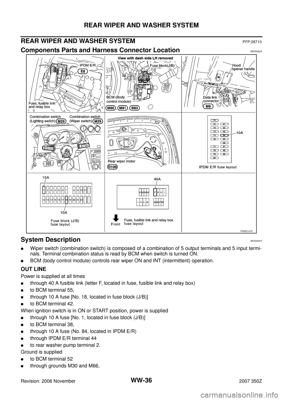
Components Parts and Harness Connector LocationNKS0052X
System DescriptionNKS0052Y
�Wiper switch (combination switch) is composed of a combination of 5 output terminals and 5 input termi-
nals. Terminal combination status is read by BCM when switch is turned ON.
�BCM (body control module) controls rear wiper ON and INT (intermittent) operation.
OUT LINE
Power is supplied at all times
�through 40 A fusible link (letter F, located in fuse, fusible link and relay box)
�to BCM terminal 55,
�through 10 A fuse [No. 18, located in fuse block (J/B)]
�to BCM terminal 42.
When ignition switch is in ON or START position, power is supplied
�through 10 A fuse [No. 1, located in fuse block (J/B)]
�to BCM terminal 38,
�through 10 A fuse (No. 84, located in IPDM E/R)
�through IPDM E/R terminal 44
�to rear washer pump terminal 2.
Ground is supplied
�to BCM terminal 52
�through grounds M30 and M66,
PKIB2147E