brake NISSAN 370Z COUPE 2014 Z34 Service Manual
[x] Cancel search | Manufacturer: NISSAN, Model Year: 2014, Model line: 370Z COUPE, Model: NISSAN 370Z COUPE 2014 Z34Pages: 428, PDF Size: 2.14 MB
Page 316 of 428
The Vehicle Dynamic Control (VDC) system
uses various sensors to monitor driver inputs
and vehicle motion. Under certain driving con-
ditions, the VDC system helps to perform the
following functions.
.Controls brake pressure to reduce wheel
slip on one slipping drive wheel so power is
transferred to a non slipping drive wheel on
the same axle.
. Controls brake pressure and engine output
to reduce drive wheel slip based on vehicle
speed (traction control function) .
. Controls brake pressure at individual wheels
and engine output to help the driver maintain
control of the vehicle in the following
conditions:
— understeer (vehicle tends to not follow
the steered path despite increased
steering input)
— oversteer (vehicle tends to spin due to certain road or driving conditions) .
The VDC system can help the driver to maintain
control of the vehicle, but it cannot prevent loss
of vehicle control in all driving situations.
When the VDC system operates, the VDC
warning light
in the instrument panel flashes
so note the following:
. The road may be slippery or the system may
determine some action is required to help keep the vehicle on the steered path.
. You may feel a pulsation in the brake pedal
and hear a noise or vibration from under the
hood. This is normal and indicates that the
VDC system is working properly.
. Adjust your speed and driving to the road
conditions.
See “Vehicle Dynamic Control (VDC) warning
light” (P.2-15).
If a malfunction occurs in the system, the VDC
warning light
illuminates in the instrument
panel. The VDC system automatically turns off.
The VDC OFF switch is used to turn off the VDC
system. The VDC off indicator
illuminates to
indicate the VDC system is off. When the VDC
switch is used to turn off the system, the VDC
system still operates to prevent one drive wheel
from slipping by transferring power to a non
slipping drive wheel. The VDC warning light
flashes if this occurs. All other VDC functions
are off, and the VDC warning lightwill not
flash. The VDC system is automatically reset to
on when the ignition switch is placed in the off
position then back to the on position.
See “Vehicle Dynamic Control (VDC) warning
light” (P.2-15) and “Vehicle Dynamic Control
(VDC) off indicator light” (P.2-17).
The computer has a built-in diagnostic feature
that tests the system each time you start the engine and move the vehicle forward or in
reverse at a slow speed. When the self-test
occurs, you may hear a “clunk” noise and/or feel
a pulsation in the brake pedal. This is normal and
is not an indication of a malfunction.
WARNING
.
The VDC system is designed to help
the driver maintain stability but
does not prevent accidents due to
abrupt steering operation at high
speeds or by careless or dangerous
driving techniques. Reduce vehicle
speed and be especially careful
when driving and cornering on slip-
pery surfaces and always drive care-
fully.
. Do not modify the vehicle’s suspen-
sion. If suspension parts such as
shock absorbers, struts, springs,
stabilizer bars, bushings and
wheels are not NISSAN recom-
mended for your vehicle or are
extremely deteriorated, the VDC
system may not operate properly.
This could adversely affect vehicle
handling performance, and the VDC
warning light
may illuminate.
Starting and driving5-29
VEHICLE DYNAMIC CONTROL (VDC)
SYSTEM
Page 317 of 428
5-30Starting and driving
.If brake related parts such as brake
pads, rotors and calipers are not
NISSAN recommended or are extre-
mely deteriorated, the VDC system
may not operate properly and the
VDC warning light
may illumi-
nate.
. If engine control related parts are
not NISSAN recommended or are
extremely deteriorated, the VDC
warning light
may illuminate.
. When driving on extremely inclined
surfaces such as higher banked
corners, the VDC system may not
operate properly and the VDC warn-
ing light
may illuminate. Do not
drive on these types of roads.
. When driving on an unstable sur-
face such as a turntable, ferry,
elevator or ramp, the VDC warning
light
may illuminate. This is not
a malfunction. Restart the engine
after driving onto a stable surface.
. If wheels or tires other than the
NISSAN recommended ones are
used, the VDC system may not
operate properly and the VDC warn-
ing light
may illuminate. .
The VDC system is not a substitute
for winter tires or tire chains on a
snow covered road.
Page 320 of 428
.Watch for slippery spots (glare ice) .
These may appear on an otherwise
clear road in shaded areas. If a
patch of ice is seen ahead, brake
before reaching it. Try not to brake
while on the ice, and avoid any
sudden steering maneuvers.
. Do not use the cruise control on
slippery roads.
. Snow can trap dangerous exhaust
gases under your vehicle. Keep
snow clear of the exhaust pipe and
from around your vehicle.
ENGINE BLOCK HEATER (if so
equipped)
Engine block heaters are used to assist with
cold temperature starting.
The engine block heater should be used when
the outside temperature is 208F( −78C) or lower.
To use the engine block heater
1. Turn the engine off.
2. Open the hood and unwrap the engine
block heater cord.
3. Plug the engine block heater cord into a grounded 3-wire, 3-pronged extension cord. 4. Plug the extension cord into a Ground Fault
Interrupt (GFI) protected, grounded 110-
volt AC (VAC) outlet.
5. The engine block heater must be plugged in for at least 2 - 4 hours, depending on
outside temperatures, to properly warm the
engine coolant. Use an appropriate timer to
turn the engine block heater on.
6. Before starting the engine, unplug and properly store the cord to keep it away from
moving parts.
WARNING
.Do not use your engine block heater
with an ungrounded electrical sys-
tem or a 2-pronged adapter. You can
be seriously injured by an electrical
shock if you use an ungrounded
connection.
. Disconnect and properly store the
engine block heater cord before
starting the engine. Damage to the
cord could result in an electrical
shock and can cause serious injury.
. Use a heavy-duty 3-wire, 3-pronged
extension cord rated for at least
10A. Plug the extension cord into a Ground Fault Interrupt (GFI) pro-
tected, grounded 110-VAC outlet.
Failure to use the proper extension
cord or a grounded outlet can result
in a fire or electrical shock and
cause serious personal injury.
Starting and driving5-33
Page 325 of 428
6-4In case of emergency
CHANGING A FLAT TIRE (for models
with spare tire)
If you have a flat tire, follow the instructions
below.
Stopping the vehicle
1. Safely move the vehicle off the road andaway from traffic.
2. Turn on the hazard warning flashers.
3. Park on a level surface and apply the parking brake. Move the shift lever to the P (Park)
position (Automatic transmission models) .
Move the shift lever to the R (Reverse) gear
(Manual transmission models) .
4. Turn off the engine.
5. Raise the hood to warn other traffic, and to signal professional road assistance person-
nel that you need assistance.
6. Have all passengers get out of the vehicle and stand in a safe place, away from traffic
and clear of the vehicle.
WARNING
.Make sure the parking brake is
securely applied and the manual
transmission is shifted into R (Re-
verse) , or the automatic transmis- sion into P (Park) .
. Never change tires when the vehicle
is on a slope, ice or slippery areas.
This is hazardous.
. Never change tires if oncoming
traffic is close to your vehicle. Wait
for professional road assistance.
MCE0001A
Blocking wheels
Place suitable blocks*1at both the front and
back of the wheel diagonally opposite the flat
tire to prevent the vehicle from moving when it is
jacked up.
WARNING
Be sure to block the wheel as the
vehicle may move and result in personal
injury.
Page 328 of 428
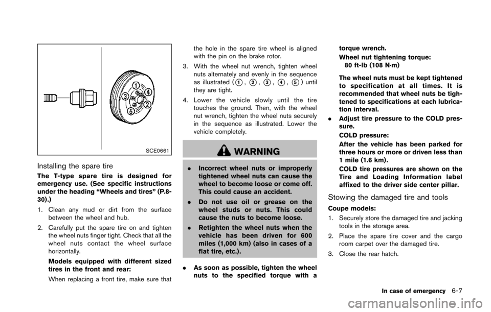
SCE0661
Installing the spare tire
The T-type spare tire is designed for
emergency use. (See specific instructions
under the heading “Wheels and tires” (P.8-
30) .)
1. Clean any mud or dirt from the surfacebetween the wheel and hub.
2. Carefully put the spare tire on and tighten the wheel nuts finger tight. Check that all the
wheel nuts contact the wheel surface
horizontally.
Models equipped with different sized
tires in the front and rear:
When replacing a front tire, make sure that the hole in the spare tire wheel is aligned
with the pin on the brake rotor.
3. With the wheel nut wrench, tighten wheel nuts alternately and evenly in the sequence
as illustrated (
*1,*2,*3,*4,*5) until
they are tight.
4. Lower the vehicle slowly until the tire touches the ground. Then, with the wheel
nut wrench, tighten the wheel nuts securely
in the sequence as illustrated. Lower the
vehicle completely.
WARNING
.Incorrect wheel nuts or improperly
tightened wheel nuts can cause the
wheel to become loose or come off.
This could cause an accident.
. Do not use oil or grease on the
wheel studs or nuts. This could
cause the nuts to become loose.
. Retighten the wheel nuts when the
vehicle has been driven for 600
miles (1,000 km) (also in cases of a
flat tire, etc.) .
. As soon as possible, tighten the wheel
nuts to the specified torque with a torque wrench.
Wheel nut tightening torque:
80 ft-lb (108 N·m)
The wheel nuts must be kept tightened
to specification at all times. It is
recommended that wheel nuts be tigh-
tened to specifications at each lubrica-
tion interval.
. Adjust tire pressure to the COLD pres-
sure.
COLD pressure:
After the vehicle has been parked for
three hours or more or driven less than
1 mile (1.6 km) .
COLD tire pressures are shown on the
Tire and Loading Information label
affixed to the driver side center pillar.
Stowing the damaged tire and tools
Coupe models:
1. Securely store the damaged tire and jacking
tools in the storage area.
2. Place the spare tire cover and the cargo room carpet over the damaged tire.
3. Close the rear hatch.
In case of emergency6-7
Page 330 of 428
CAUTION
.To avoid the emergency tire punc-
ture kit being damaged during sto-
rage or use:
— Only use the emergency tire
puncture repair kit on your ve-
hicle. Do not use it on other
vehicles.
— Only use the kit to inflate the tires of your vehicle and to
check the vehicle’s tire pressure.
— Only plug the compressor into a 12V DC car power point.
— Keep the kit free of water and dirt.
— Do not disassemble or modify the kit.
— Do not drop the kit or allow hard impacts to the kit.
. Do not use the emergency tire
puncture repair kit under the follow-
ing conditions. Contact a NISSAN
dealer or professional road assis-
tance. — when the sealant has passed its
expiration date (shown on the
label attached to the bottle)
— when the cut or the puncture is approximately 0.25 in (6 mm) or
longer
— when the tire sidewall is da- maged
— when the vehicle has been dri- ven with extremely low tire
pressure
— when the tire has come off the inside or the outside of the
wheel.
— when the tire wheel is damaged
— when two or more tires are flat
Stopping the vehicle
1. Safely move the vehicle off the road and away from traffic.
2. Turn on the hazard warning flashers.
3. Park on a level surface and apply the parking brake.
4. Automatic Transmission models:
Move the shift lever to the P (Park) position. Manual Transmission models:
Move the shift lever to the R (Reverse)
position.
5. Turn off the engine.
6. Raise the hood to warn other traffic and to signal professional road assistance person-
nel that you need assistance.
7. Have all passengers get out of the vehicle and stand in a safe place, away from traffic
and clear of the vehicle.
WARNING
Make sure the parking brake is securely
applied and the manual transmission is
shifted into R (Reverse) or the auto-
matic transmission into P (Park) .
.Never repair tires when the vehicle
is on a slope, ice or slippery areas.
This is hazardous.
. Never repair tires if oncoming traffic
is close to your vehicle. Wait for
professional road assistance.
In case of emergency6-9
Page 336 of 428
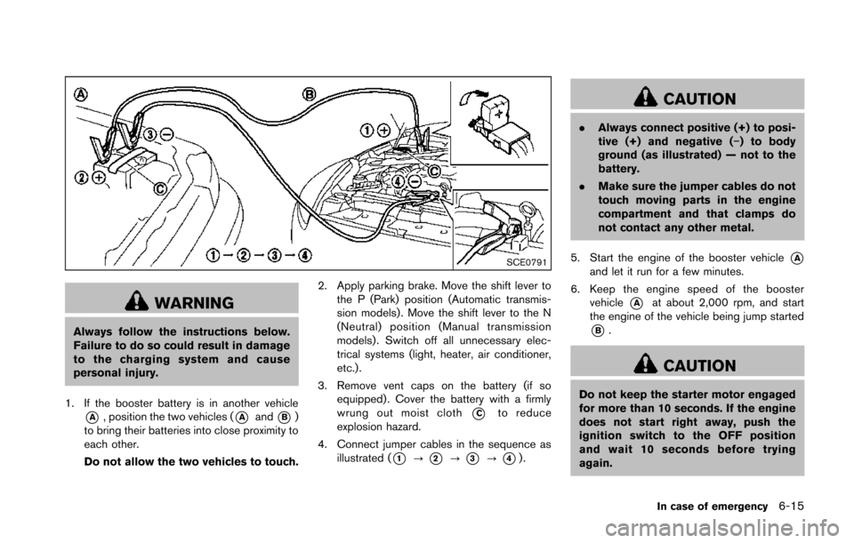
SCE0791
WARNING
Always follow the instructions below.
Failure to do so could result in damage
to the charging system and cause
personal injury.
1. If the booster battery is in another vehicle
*A, position the two vehicles (*Aand*B)
to bring their batteries into close proximity to
each other.
Do not allow the two vehicles to touch. 2. Apply parking brake. Move the shift lever to
the P (Park) position (Automatic transmis-
sion models). Move the shift lever to the N
(Neutral) position (Manual transmission
models) . Switch off all unnecessary elec-
trical systems (light, heater, air conditioner,
etc.).
3. Remove vent caps on the battery (if so equipped) . Cover the battery with a firmly
wrung out moist cloth*Cto reduce
explosion hazard.
4. Connect jumper cables in the sequence as illustrated (
*1?*2?*3?*4).
CAUTION
.Always connect positive (+) to posi-
tive (+) and negative (−) to body
ground (as illustrated) — not to the
battery.
. Make sure the jumper cables do not
touch moving parts in the engine
compartment and that clamps do
not contact any other metal.
5. Start the engine of the booster vehicle
*Aand let it run for a few minutes.
6. Keep the engine speed of the booster vehicle
*Aat about 2,000 rpm, and start
the engine of the vehicle being jump started
*B.
CAUTION
Do not keep the starter motor engaged
for more than 10 seconds. If the engine
does not start right away, push the
ignition switch to the OFF position
and wait 10 seconds before trying
again.
In case of emergency6-15
Page 337 of 428
6-16In case of emergency
7. After starting your engine, carefully discon-nect the negative cable and then the positive
cable (
*4?*3?*2?*1).
8. Replace the vent caps (if so equipped). Be sure to dispose of the cloth used to cover
the vent holes as it may be contaminated
with corrosive acid.
9. Put the battery cover on. Do not attempt to start the engine by pushing.CAUTION
.
Automatic transmission models
cannot be push-started or tow-
started. Attempting to do so may
cause transmission damage.
. Three way catalyst equipped models
should not be started by pushing
since the three way catalyst may be
damaged.
. Never try to start the vehicle by
towing it; when the engine starts,
the forward surge could cause the
vehicle to collide with the tow
vehicle.
CAUTION
.Do not continue to drive if your
vehicle overheats. Doing so could
cause engine damage or a vehicle
fire.
. To avoid the danger of being
scalded, never remove the radiator
cap while the engine is still hot.
When the radiator cap is removed,
pressurized hot water will spurt out,
possibly causing serious injury.
. Do not open the hood if steam is
coming out.
If your vehicle is overheating (indicated by an
extremely high temperature gauge reading) , or if
you feel a lack of engine power, detect abnormal
noise, etc., take the following steps:
1. Move the vehicle safely off the road, apply the parking brake and move the shift lever to
the P (Park) position (Automatic transmis-
sion models). Move the shift lever to the N
(Neutral) position (Manual transmission
models) .
Do not stop the engine.
PUSH STARTING IF YOUR VEHICLE OVERHEATS
Page 340 of 428
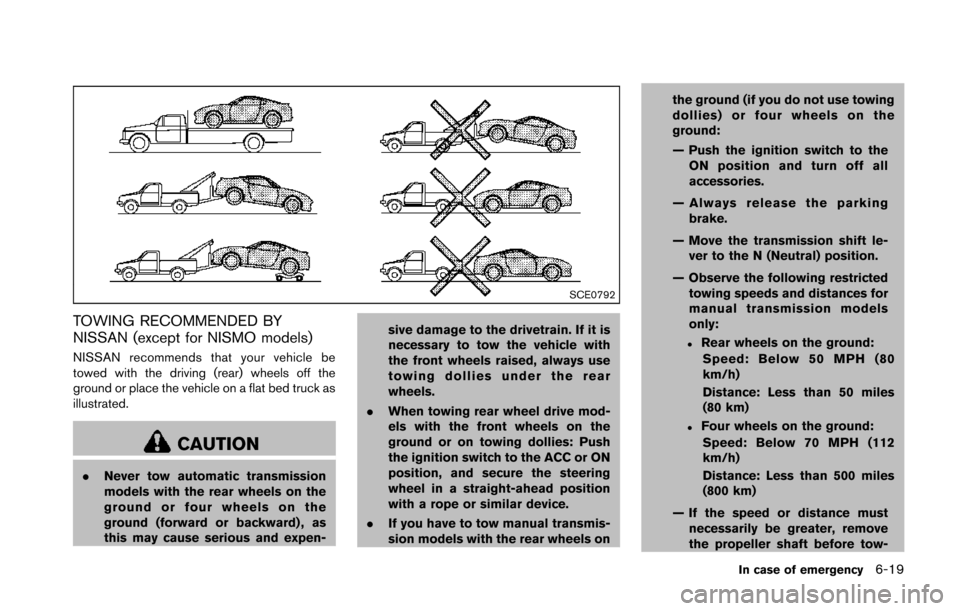
SCE0792
TOWING RECOMMENDED BY
NISSAN (except for NISMO models)
NISSAN recommends that your vehicle be
towed with the driving (rear) wheels off the
ground or place the vehicle on a flat bed truck as
illustrated.
CAUTION
.Never tow automatic transmission
models with the rear wheels on the
ground or four wheels on the
ground (forward or backward) , as
this may cause serious and expen- sive damage to the drivetrain. If it is
necessary to tow the vehicle with
the front wheels raised, always use
towing dollies under the rear
wheels.
. When towing rear wheel drive mod-
els with the front wheels on the
ground or on towing dollies: Push
the ignition switch to the ACC or ON
position, and secure the steering
wheel in a straight-ahead position
with a rope or similar device.
. If you have to tow manual transmis-
sion models with the rear wheels on the ground (if you do not use towing
dollies) or four wheels on the
ground:
— Push the ignition switch to the
ON position and turn off all
accessories.
— Always release the parking brake.
— Move the transmission shift le- ver to the N (Neutral) position.
— Observe the following restricted towing speeds and distances for
manual transmission models
only:
.Rear wheels on the ground:
Speed: Below 50 MPH (80
km/h)
Distance: Less than 50 miles
(80 km)
.Four wheels on the ground:Speed: Below 70 MPH (112
km/h)
Distance: Less than 500 miles
(800 km)
— If the speed or distance must necessarily be greater, remove
the propeller shaft before tow-
In case of emergency6-19
Page 343 of 428
6-22In case of emergency
.Always pull the cable straight out
from the front of the vehicle. Never
pull on the vehicle at an angle.
. Pulling devices should be routed so
they do not touch any part of the
suspension, steering, brake or cool-
ing systems.
. Pulling devices such as ropes or
canvas straps are not recommended
for use in vehicle towing or recov-
ery.
Rocking a stuck vehicle
If your vehicle is stuck in sand, snow, mud, etc.,
use the following procedure:
1. Turn off the Vehicle Dynamic Control (VDC)
system.
2. Make sure the area in front and behind the vehicle is clear of obstructions.
3. Turn the steering wheel right and left to clear an area around the front tires.
4. Slowly rock the vehicle forward and back- ward.
.Shift back and forth between R (Reverse)
and D (Drive) (automatic transmission
models) or 1st and R (Reverse) (manual
transmission models) .
.Apply the accelerator as little as possibleto maintain the rocking motion.
.Release the accelerator pedal beforeshifting between R (Reverse) and D
(Drive) (automatic transmission models)
or 1st and R (Reverse) (manual transmis-
sion models) .
.Do not spin the tires above 35 MPH (55 km/h).
5. If the vehicle cannot be freed after a few tries, contact a professional towing service
to remove the vehicle.