NISSAN ALMERA 2001 Service Manual
Manufacturer: NISSAN, Model Year: 2001, Model line: ALMERA, Model: NISSAN ALMERA 2001Pages: 2898, PDF Size: 60.76 MB
Page 1111 of 2898
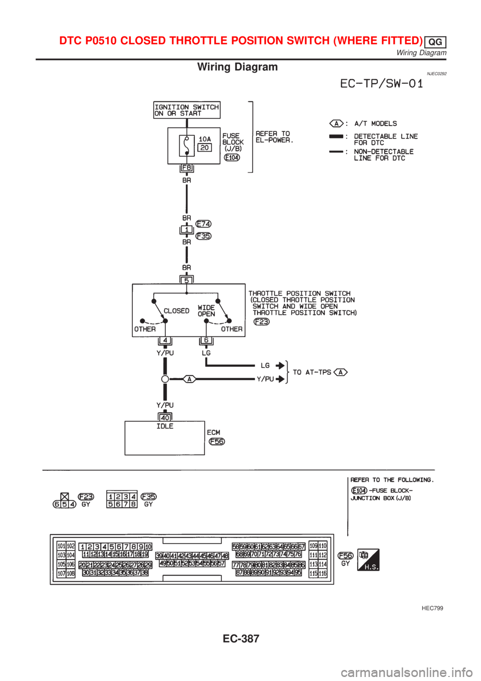
Wiring DiagramNJEC0292
HEC799
DTC P0510 CLOSED THROTTLE POSITION SWITCH (WHERE FITTED)QG
Wiring Diagram
EC-387
Page 1112 of 2898
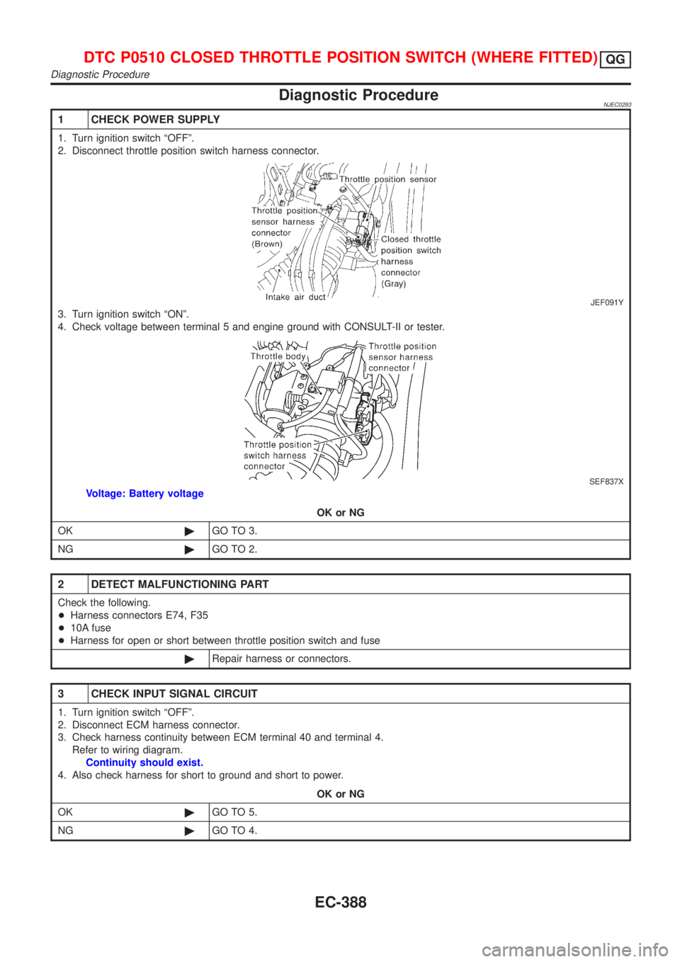
Diagnostic ProcedureNJEC0293
1 CHECK POWER SUPPLY
1. Turn ignition switch ªOFFº.
2. Disconnect throttle position switch harness connector.
JEF091Y
3. Turn ignition switch ªONº.
4. Check voltage between terminal 5 and engine ground with CONSULT-II or tester.
SEF837X
Voltage: Battery voltage
OK or NG
OK©GO TO 3.
NG©GO TO 2.
2 DETECT MALFUNCTIONING PART
Check the following.
+Harness connectors E74, F35
+10A fuse
+Harness for open or short between throttle position switch and fuse
©Repair harness or connectors.
3 CHECK INPUT SIGNAL CIRCUIT
1. Turn ignition switch ªOFFº.
2. Disconnect ECM harness connector.
3. Check harness continuity between ECM terminal 40 and terminal 4.
Refer to wiring diagram.
Continuity should exist.
4. Also check harness for short to ground and short to power.
OK or NG
OK©GO TO 5.
NG©GO TO 4.
DTC P0510 CLOSED THROTTLE POSITION SWITCH (WHERE FITTED)QG
Diagnostic Procedure
EC-388
Page 1113 of 2898
4 DETECT MALFUNCTIONING PART
Check the following.
+Harness for open or short between throttle position switch and ECM
+Harness for open or short between throttle position switch and TCM (Transmission Control Module)
©Repair open circuit or short to ground or short to power in harness or connectors.
5 ADJUST THROTTLE POSITION SWITCH IDLE POSITION
Perform Basic Inspection, EC-100.
©GO TO 6.
6 CHECK CLOSED THROTTLE POSITION SWITCH
Refer to ªComponent Inspectionº, EC-389.
OK or NG
OK©GO TO 7.
NG©Replace throttle position switch.
7 CHECK THROTTLE POSITION SENSOR
Refer to ªComponent Inspectionº, EC-214.
OK or NG
OK©GO TO 8.
NG©Replace throttle position sensor.
8 CHECK INTERMITTENT INCIDENT
Perform ªTROUBLE DIAGNOSIS FOR INTERMITTENT INCIDENTº, EC-177.
©INSPECTION END
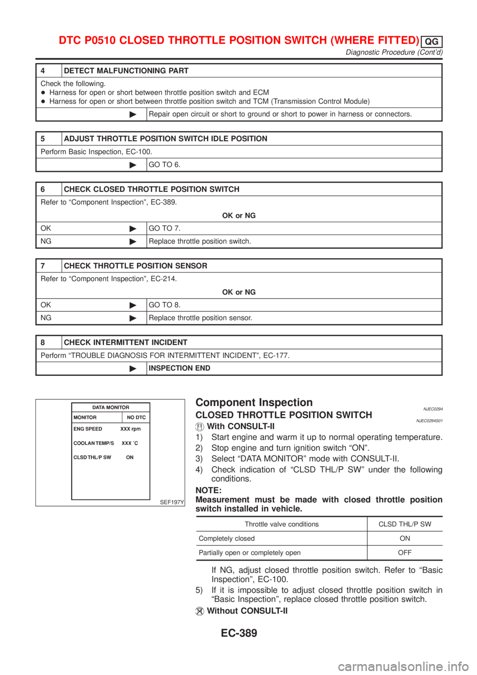
SEF197Y
Component InspectionNJEC0294CLOSED THROTTLE POSITION SWITCHNJEC0294S01With CONSULT-II
1) Start engine and warm it up to normal operating temperature.
2) Stop engine and turn ignition switch ªONº.
3) Select ªDATA MONITORº mode with CONSULT-II.
4) Check indication of ªCLSD THL/P SWº under the following
conditions.
NOTE:
Measurement must be made with closed throttle position
switch installed in vehicle.
Throttle valve conditions CLSD THL/P SW
Completely closed ON
Partially open or completely open OFF
If NG, adjust closed throttle position switch. Refer to ªBasic
Inspectionº, EC-100.
5) If it is impossible to adjust closed throttle position switch in
ªBasic Inspectionº, replace closed throttle position switch.
Without CONSULT-II
DTC P0510 CLOSED THROTTLE POSITION SWITCH (WHERE FITTED)QG
Diagnostic Procedure (Cont'd)
EC-389
Page 1114 of 2898
1) Start engine and warm it up to normal operating temperature.
2) Turn ignition switch ªOFFº.
3) Disconnect throttle position switch harness connector.
4) Check continuity between terminals 4 and 5 under the follow-
ing conditions. Refer to wiring diagram.
NOTE:
Continuity measurement must be made with closed throttle
position switch installed in vehicle.
Throttle valve conditions Continuity
Completely closed Yes
Partially open or completely open No
If NG, adjust closed throttle position switch. Refer to ªBasic
Inspectionº, EC-100.
5) If it is impossible to adjust closed throttle position switch in
ªBasic Inspectionº, replace closed throttle position switch.
DTC P0510 CLOSED THROTTLE POSITION SWITCH (WHERE FITTED)QG
Component Inspection (Cont'd)
EC-390
Page 1115 of 2898
SEF093X
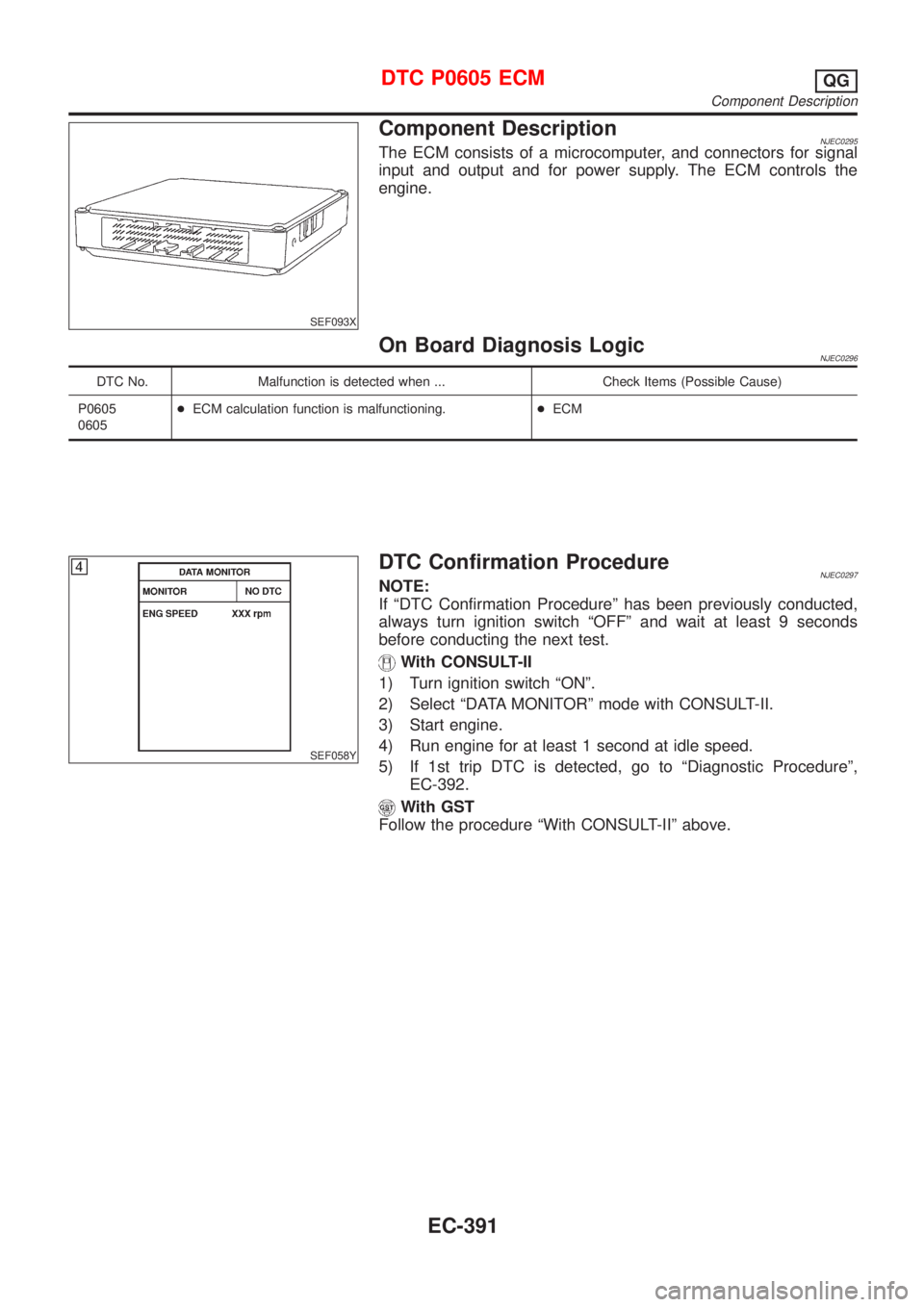
Component DescriptionNJEC0295The ECM consists of a microcomputer, and connectors for signal
input and output and for power supply. The ECM controls the
engine.
On Board Diagnosis LogicNJEC0296
DTC No. Malfunction is detected when ... Check Items (Possible Cause)
P0605
0605+ECM calculation function is malfunctioning.+ECM
SEF058Y
DTC Confirmation ProcedureNJEC0297NOTE:
If ªDTC Confirmation Procedureº has been previously conducted,
always turn ignition switch ªOFFº and wait at least 9 seconds
before conducting the next test.
With CONSULT-II
1) Turn ignition switch ªONº.
2) Select ªDATA MONITORº mode with CONSULT-II.
3) Start engine.
4) Run engine for at least 1 second at idle speed.
5) If 1st trip DTC is detected, go to ªDiagnostic Procedureº,
EC-392.
With GST
Follow the procedure ªWith CONSULT-IIº above.
DTC P0605 ECMQG
Component Description
EC-391
Page 1116 of 2898
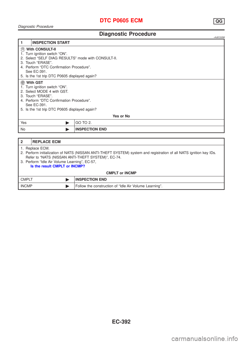
Diagnostic Procedure=NJEC0298
1 INSPECTION START
With CONSULT-II
1. Turn ignition switch ªONº.
2. Select ªSELF DIAG RESULTSº mode with CONSULT-II.
3. Touch ªERASEº.
4. Perform ªDTC Confirmation Procedureº.
See EC-391.
5. Is the 1st trip DTC P0605 displayed again?
With GST
1. Turn ignition switch ªONº.
2. Select MODE 4 with GST.
3. Touch ªERASEº.
4. Perform ªDTC Confirmation Procedureº.
See EC-391.
5. Is the 1st trip DTC P0605 displayed again?
YesorNo
Ye s©GO TO 2.
No©INSPECTION END
2 REPLACE ECM
1. Replace ECM.
2. Perform initialization of NATS (NISSAN ANTI-THEFT SYSTEM) system and registration of all NATS ignition key IDs.
Refer to ªNATS (NISSAN ANTI-THEFT SYSTEM)º, EC-74.
3. Perform ªIdle Air Volume Learningº, EC-57,
Is the result CMPLT or INCMP?
CMPLT or INCMP
CMPLT©INSPECTION END
INCMP©Follow the construction of ªIdle Air Volume Learningº.
DTC P0605 ECMQG
Diagnostic Procedure
EC-392
Page 1117 of 2898
SEF095X
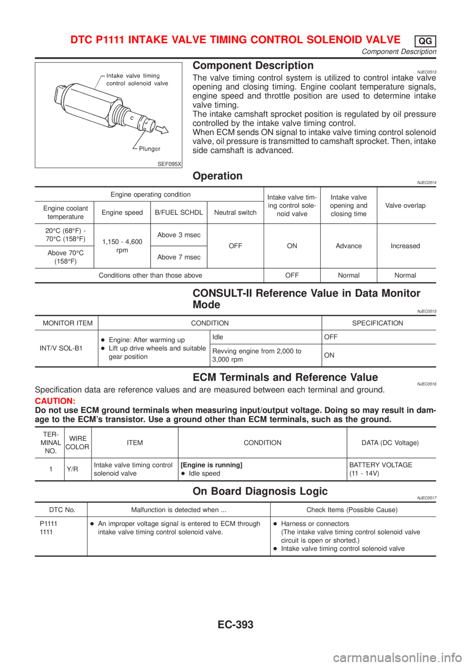
Component DescriptionNJEC0513The valve timing control system is utilized to control intake valve
opening and closing timing. Engine coolant temperature signals,
engine speed and throttle position are used to determine intake
valve timing.
The intake camshaft sprocket position is regulated by oil pressure
controlled by the intake valve timing control.
When ECM sends ON signal to intake valve timing control solenoid
valve, oil pressure is transmitted to camshaft sprocket. Then, intake
side camshaft is advanced.
OperationNJEC0514
Engine operating condition
Intake valve tim-
ing control sole-
noid valveIntake valve
opening and
closing timeValve overlap
Engine coolant
temperatureEngine speed B/FUEL SCHDL Neutral switch
20ÉC (68ÉF) -
70ÉC (158ÉF)
1,150 - 4,600
rpmAbove 3 msec
OFF ON Advance Increased
Above 70ÉC
(158ÉF)Above 7 msec
Conditions other than those above OFF Normal Normal
CONSULT-II Reference Value in Data Monitor
Mode
NJEC0515
MONITOR ITEM CONDITION SPECIFICATION
INT/V SOL-B1+Engine: After warming up
+Lift up drive wheels and suitable
gear positionIdle OFF
Revving engine from 2,000 to
3,000 rpmON
ECM Terminals and Reference ValueNJEC0516Specification data are reference values and are measured between each terminal and ground.
CAUTION:
Do not use ECM ground terminals when measuring input/output voltage. Doing so may result in dam-
age to the ECM's transistor. Use a ground other than ECM terminals, such as the ground.
TER-
MINAL
NO.WIRE
COLORITEM CONDITION DATA (DC Voltage)
1 Y/RIntake valve timing control
solenoid valve[Engine is running]
+Idle speedBATTERY VOLTAGE
(11 - 14V)
On Board Diagnosis LogicNJEC0517
DTC No. Malfunction is detected when ... Check Items (Possible Cause)
P 1111
1111+An improper voltage signal is entered to ECM through
intake valve timing control solenoid valve.+Harness or connectors
(The intake valve timing control solenoid valve
circuit is open or shorted.)
+Intake valve timing control solenoid valve
D T C P 1111INTAKE VALVE TIMING CONTROL SOLENOID VALVEQG
Component Description
EC-393
Page 1118 of 2898
SEF608Y
DTC Confirmation ProcedureNJEC0518NOTE:
If ªDTC Confirmation Procedureº has been previously conducted,
always turn ignition switch ªOFFº and wait at least 9 seconds
before conducting the next test.
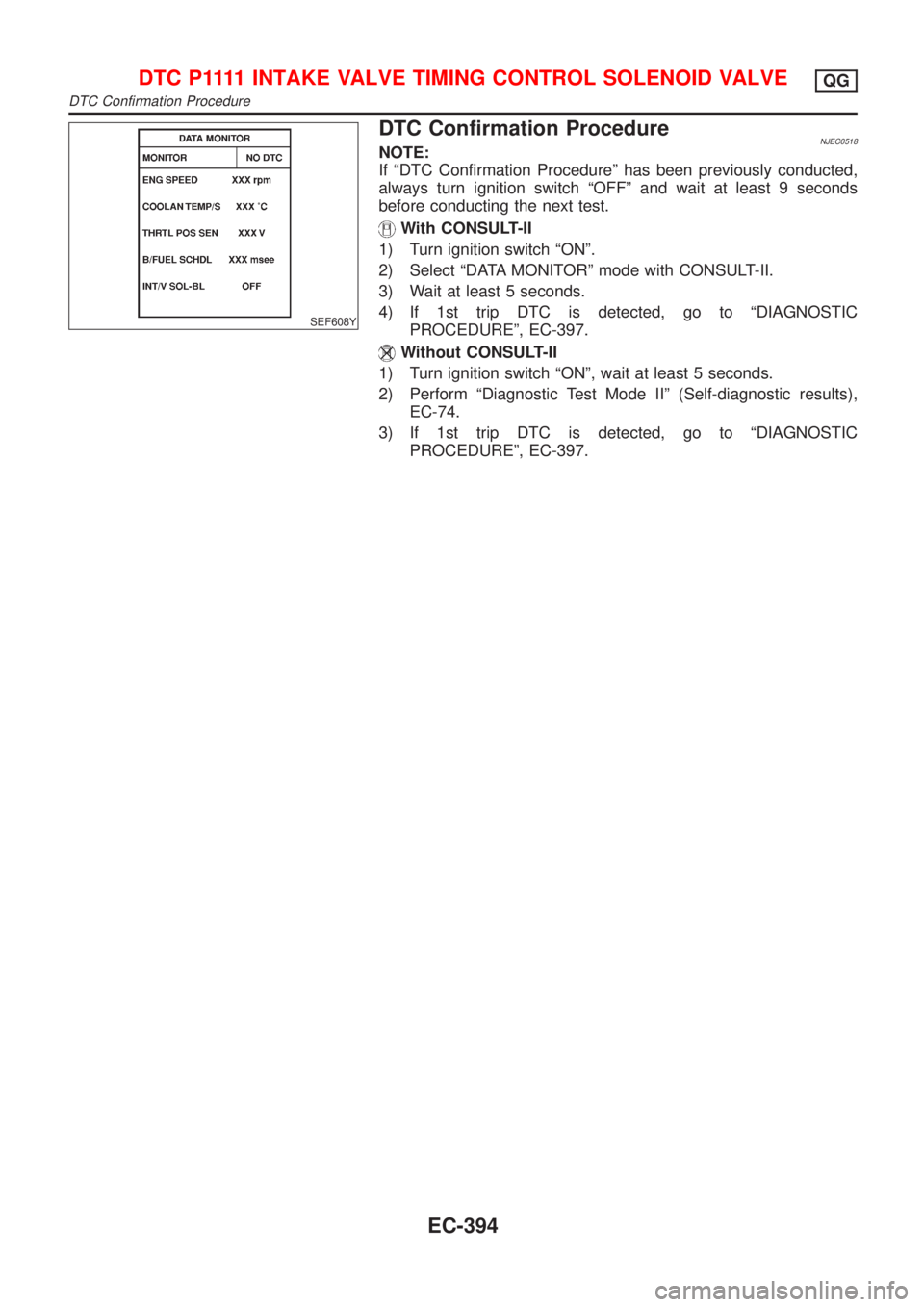
With CONSULT-II
1) Turn ignition switch ªONº.
2) Select ªDATA MONITORº mode with CONSULT-II.
3) Wait at least 5 seconds.
4) If 1st trip DTC is detected, go to ªDIAGNOSTIC
PROCEDUREº, EC-397.
Without CONSULT-II
1) Turn ignition switch ªONº, wait at least 5 seconds.
2) Perform ªDiagnostic Test Mode IIº (Self-diagnostic results),
EC-74.
3) If 1st trip DTC is detected, go to ªDIAGNOSTIC
PROCEDUREº, EC-397.
D T C P 1111INTAKE VALVE TIMING CONTROL SOLENOID VALVEQG
DTC Confirmation Procedure
EC-394
Page 1119 of 2898
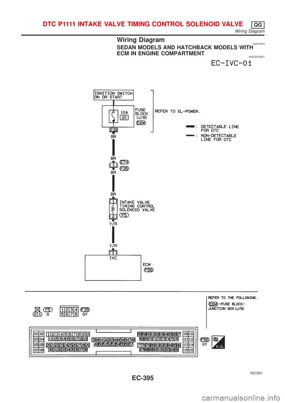
Wiring DiagramNJEC0519SEDAN MODELS AND HATCHBACK MODELS WITH
ECM IN ENGINE COMPARTMENT
NJEC0519S01
HEC801
D T C P 1111INTAKE VALVE TIMING CONTROL SOLENOID VALVEQG
Wiring Diagram
EC-395
Page 1120 of 2898
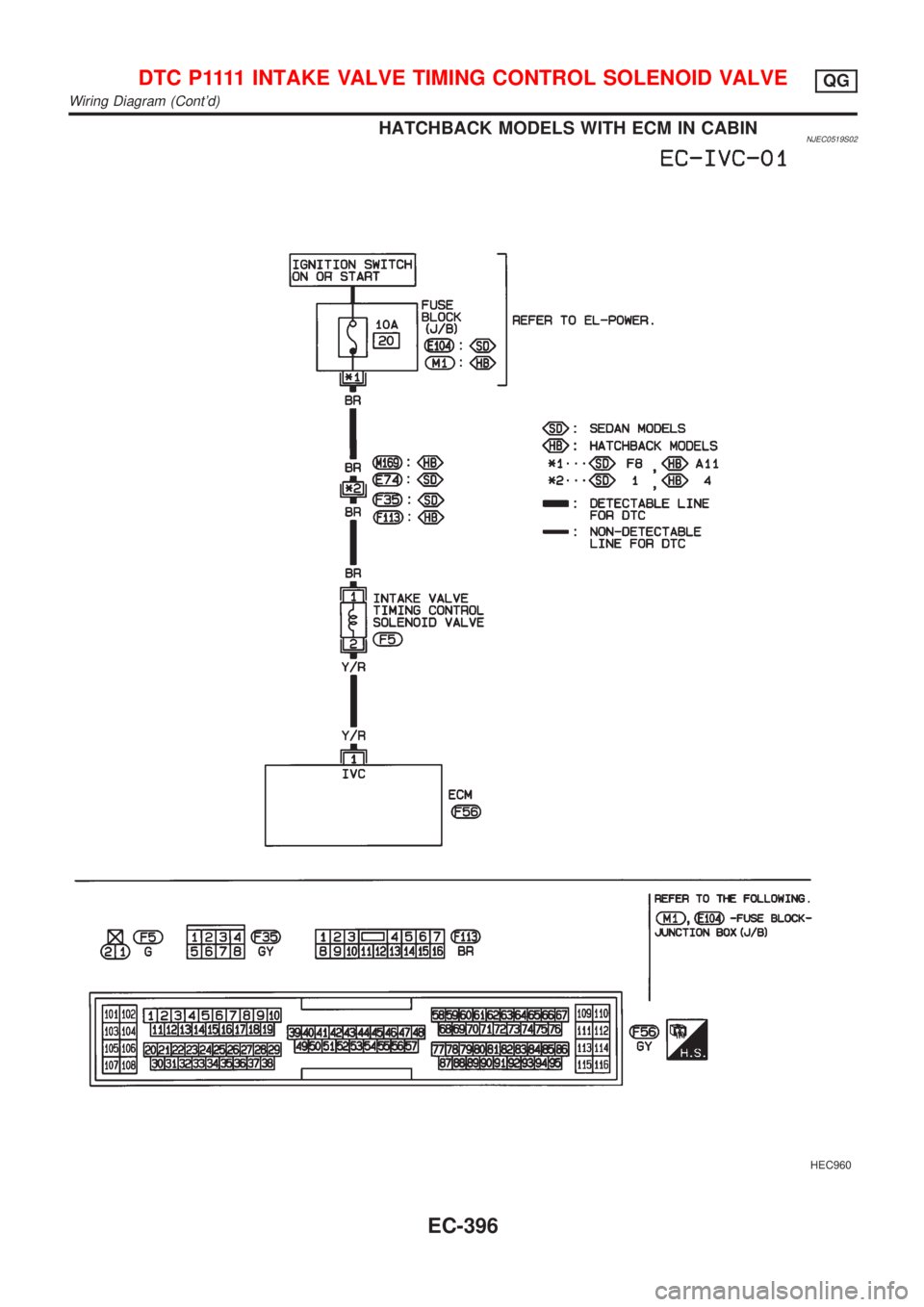
HATCHBACK MODELS WITH ECM IN CABINNJEC0519S02
HEC960
D T C P 1111INTAKE VALVE TIMING CONTROL SOLENOID VALVEQG
Wiring Diagram (Cont'd)
EC-396