NISSAN ALMERA 2001 Service Manual
Manufacturer: NISSAN, Model Year: 2001, Model line: ALMERA, Model: NISSAN ALMERA 2001Pages: 2898, PDF Size: 60.76 MB
Page 1151 of 2898
DTC No. Malfunction is detected when ... Check Items (Possible Cause)
P1402
1402+EGR flow is detected under conditions that do not call for
EGR.+Harness or connectors
(The valve circuit is open or shorted.)
+EGR volume control valve leaking or stuck open
+EGR temperature sensor
SEF202Y
SEF851Y
SEF852Y
SEF236Y
DTC Confirmation ProcedureNJEC0351NOTE:
If ªDTC Confirmation Procedureº has been previously conducted,
always turn ignition switch ªOFFº and wait at least 9 seconds
before conducting the next test.
TESTING CONDITION:
+Always perform at a temperature above þ10ÉC (14ÉF).
+Engine coolant temperature and EGR temperature must
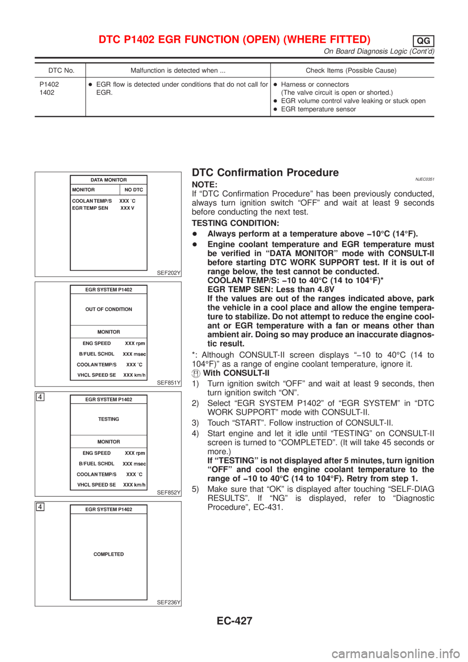
be verified in ªDATA MONITORº mode with CONSULT-II
before starting DTC WORK SUPPORT test. If it is out of
range below, the test cannot be conducted.
COOLAN TEMP/S: þ10 to 40ÉC (14 to 104ÉF)*
EGR TEMP SEN: Less than 4.8V
If the values are out of the ranges indicated above, park
the vehicle in a cool place and allow the engine tempera-
ture to stabilize. Do not attempt to reduce the engine cool-
ant or EGR temperature with a fan or means other than
ambient air. Doing so may produce an inaccurate diagnos-
tic result.
*: Although CONSULT-II screen displays ªþ10 to 40ÉC (14 to
104ÉF)º as a range of engine coolant temperature, ignore it.
With CONSULT-II
1) Turn ignition switch ªOFFº and wait at least 9 seconds, then
turn ignition switch ªONº.
2) Select ªEGR SYSTEM P1402º of ªEGR SYSTEMº in ªDTC
WORK SUPPORTº mode with CONSULT-II.
3) Touch ªSTARTº. Follow instruction of CONSULT-II.
4) Start engine and let it idle until ªTESTINGº on CONSULT-II
screen is turned to ªCOMPLETEDº. (It will take 45 seconds or
more.)
If ªTESTINGº is not displayed after 5 minutes, turn ignition
ªOFFº and cool the engine coolant temperature to the
range of þ10 to 40ÉC (14 to 104ÉF). Retry from step 1.
5) Make sure that ªOKº is displayed after touching ªSELF-DIAG
RESULTSº. If ªNGº is displayed, refer to ªDiagnostic
Procedureº, EC-431.
DTC P1402 EGR FUNCTION (OPEN) (WHERE FITTED)QG
On Board Diagnosis Logic (Cont'd)
EC-427
Page 1152 of 2898
SEF947X
With GST
1) Turn ignition switch ªONº and select ªMODE 1º with GST.
2) Check that engine coolant temperature is within the range of
þ10 to 40ÉC (14 to 104ÉF).
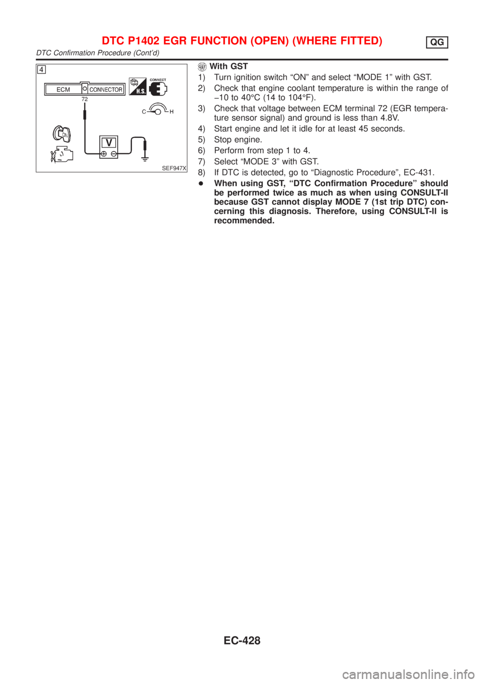
3) Check that voltage between ECM terminal 72 (EGR tempera-
ture sensor signal) and ground is less than 4.8V.
4) Start engine and let it idle for at least 45 seconds.
5) Stop engine.
6) Perform from step 1 to 4.
7) Select ªMODE 3º with GST.
8) If DTC is detected, go to ªDiagnostic Procedureº, EC-431.
+When using GST, ªDTC Confirmation Procedureº should
be performed twice as much as when using CONSULT-II
because GST cannot display MODE 7 (1st trip DTC) con-
cerning this diagnosis. Therefore, using CONSULT-II is
recommended.
DTC P1402 EGR FUNCTION (OPEN) (WHERE FITTED)QG
DTC Confirmation Procedure (Cont'd)
EC-428
Page 1153 of 2898
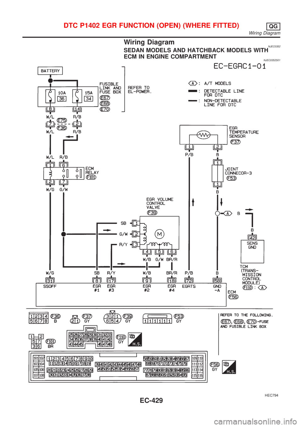
Wiring DiagramNJEC0352SEDAN MODELS AND HATCHBACK MODELS WITH
ECM IN ENGINE COMPARTMENT
NJEC0352S01
HEC794
DTC P1402 EGR FUNCTION (OPEN) (WHERE FITTED)QG
Wiring Diagram
EC-429
Page 1154 of 2898
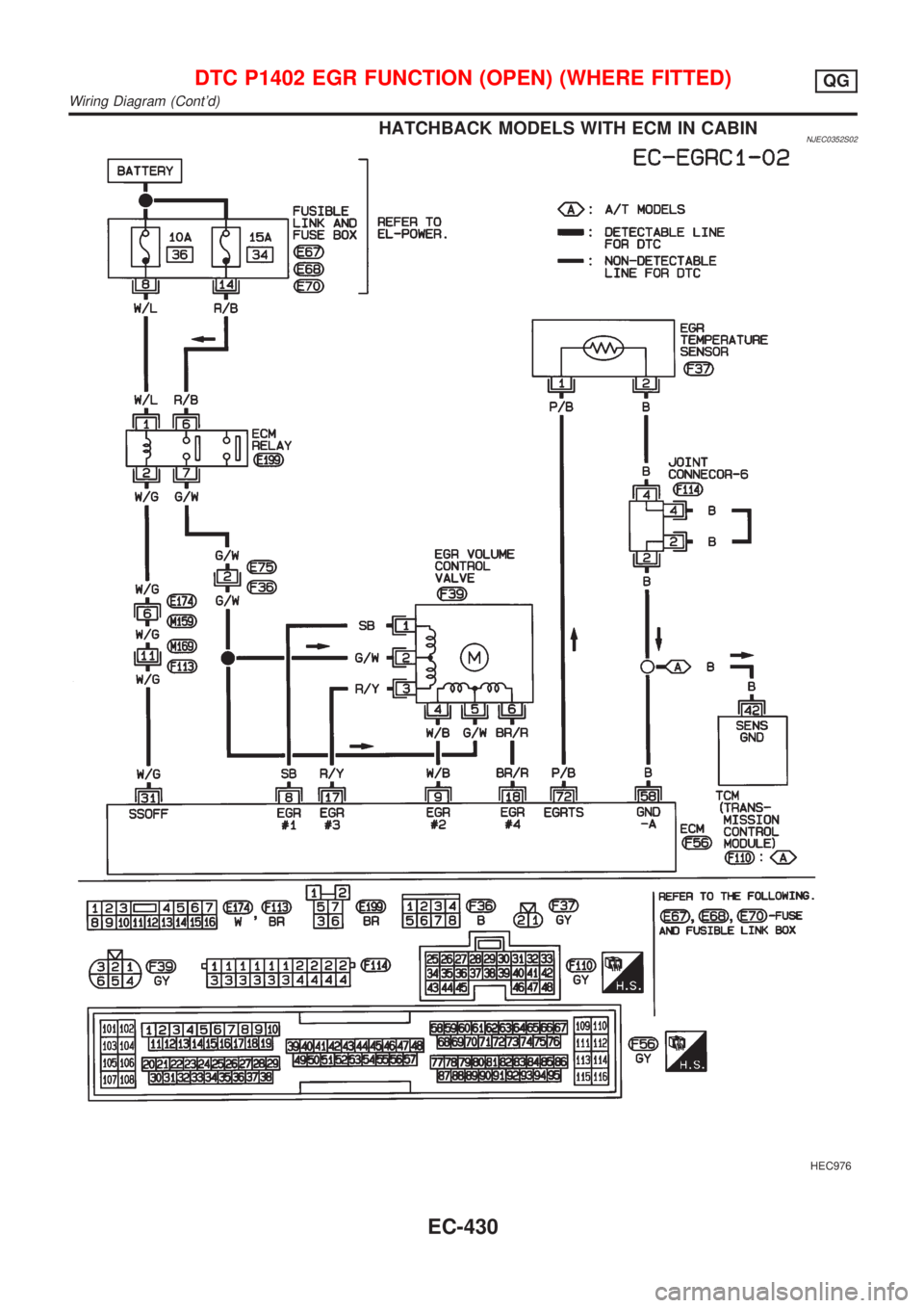
HATCHBACK MODELS WITH ECM IN CABINNJEC0352S02
HEC976
DTC P1402 EGR FUNCTION (OPEN) (WHERE FITTED)QG
Wiring Diagram (Cont'd)
EC-430
Page 1155 of 2898
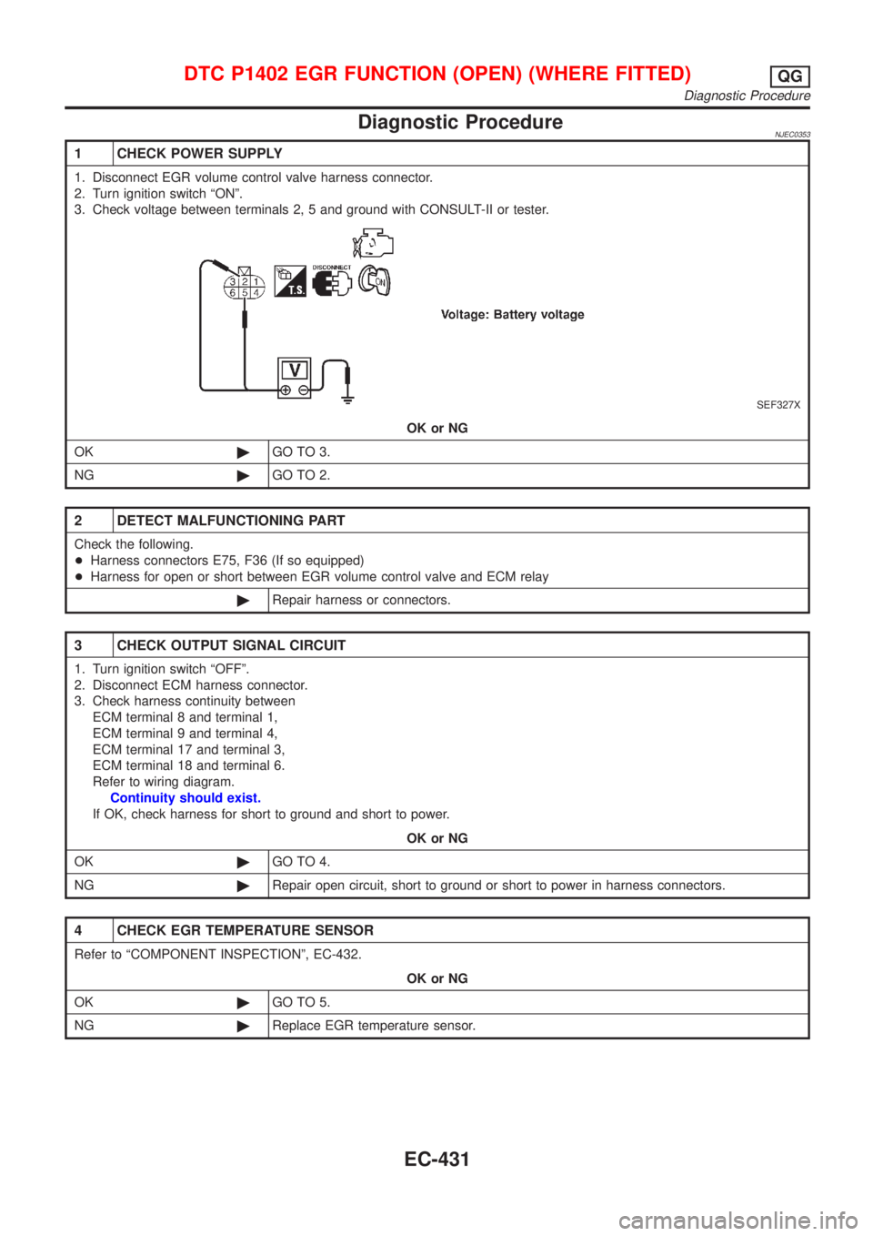
Diagnostic ProcedureNJEC0353
1 CHECK POWER SUPPLY
1. Disconnect EGR volume control valve harness connector.
2. Turn ignition switch ªONº.
3. Check voltage between terminals 2, 5 and ground with CONSULT-II or tester.
SEF327X
OK or NG
OK©GO TO 3.
NG©GO TO 2.
2 DETECT MALFUNCTIONING PART
Check the following.
+Harness connectors E75, F36 (If so equipped)
+Harness for open or short between EGR volume control valve and ECM relay
©Repair harness or connectors.
3 CHECK OUTPUT SIGNAL CIRCUIT
1. Turn ignition switch ªOFFº.
2. Disconnect ECM harness connector.
3. Check harness continuity between
ECM terminal 8 and terminal 1,
ECM terminal 9 and terminal 4,
ECM terminal 17 and terminal 3,
ECM terminal 18 and terminal 6.
Refer to wiring diagram.
Continuity should exist.
If OK, check harness for short to ground and short to power.
OK or NG
OK©GO TO 4.
NG©Repair open circuit, short to ground or short to power in harness connectors.
4 CHECK EGR TEMPERATURE SENSOR
Refer to ªCOMPONENT INSPECTIONº, EC-432.
OK or NG
OK©GO TO 5.
NG©Replace EGR temperature sensor.
DTC P1402 EGR FUNCTION (OPEN) (WHERE FITTED)QG
Diagnostic Procedure
EC-431
Page 1156 of 2898
5 CHECK EGR VOLUME CONTROL VALVE
Refer to ªCOMPONENT INSPECTIONº, EC-432.
OK or NG
OK©GO TO 6.
NG©Replace EGR volume control valve.
6 CHECK INTERMITTENT INCIDENT
Perform ªTROUBLE DIAGNOSIS FOR INTERMITTENT INCIDENTº, EC-177.
©INSPECTION END
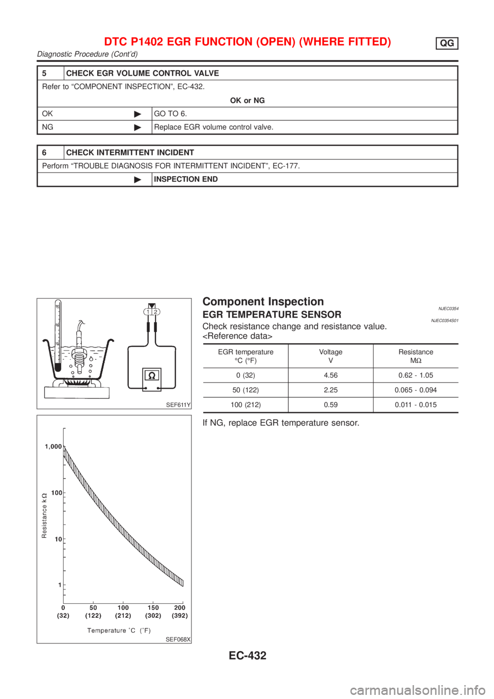
SEF611Y
SEF068X
Component InspectionNJEC0354EGR TEMPERATURE SENSORNJEC0354S01Check resistance change and resistance value.
EGR temperature
ÉC (ÉF)Voltage
VResistance
MW
0 (32) 4.56 0.62 - 1.05
50 (122) 2.25 0.065 - 0.094
100 (212) 0.59 0.011 - 0.015
If NG, replace EGR temperature sensor.
DTC P1402 EGR FUNCTION (OPEN) (WHERE FITTED)QG
Diagnostic Procedure (Cont'd)
EC-432
Page 1157 of 2898
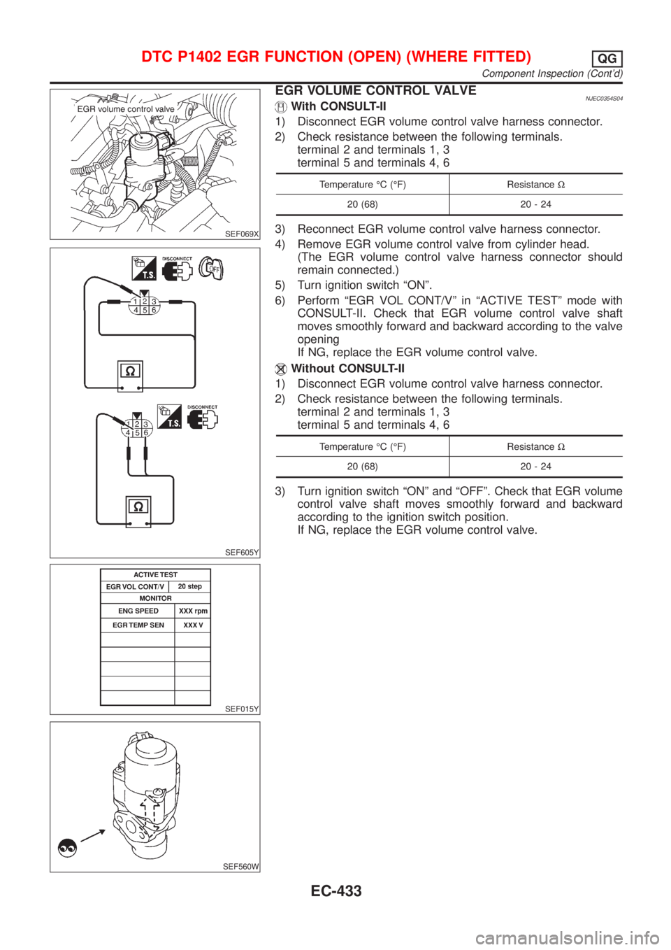
SEF069X
SEF605Y
SEF015Y
SEF560W
EGR VOLUME CONTROL VALVENJEC0354S04With CONSULT-II
1) Disconnect EGR volume control valve harness connector.
2) Check resistance between the following terminals.
terminal 2 and terminals 1, 3
terminal 5 and terminals 4, 6
Temperature ÉC (ÉF) ResistanceW
20 (68) 20 - 24
3) Reconnect EGR volume control valve harness connector.
4) Remove EGR volume control valve from cylinder head.
(The EGR volume control valve harness connector should
remain connected.)
5) Turn ignition switch ªONº.
6) Perform ªEGR VOL CONT/Vº in ªACTIVE TESTº mode with
CONSULT-II. Check that EGR volume control valve shaft
moves smoothly forward and backward according to the valve
opening
If NG, replace the EGR volume control valve.
Without CONSULT-II
1) Disconnect EGR volume control valve harness connector.
2) Check resistance between the following terminals.
terminal 2 and terminals 1, 3
terminal 5 and terminals 4, 6
Temperature ÉC (ÉF) ResistanceW
20 (68) 20 - 24
3) Turn ignition switch ªONº and ªOFFº. Check that EGR volume
control valve shaft moves smoothly forward and backward
according to the ignition switch position.
If NG, replace the EGR volume control valve.
DTC P1402 EGR FUNCTION (OPEN) (WHERE FITTED)QG
Component Inspection (Cont'd)
EC-433
Page 1158 of 2898
System DescriptionNJEC0573The malfunction information related to A/T (Automatic Transaxle) is transferred through the line (circuit) from
TCM (Transmission Control Module) to ECM. Therefore, be sure to erase the malfunction information such as
DTC not only in TCM (Transmission Control Module) but also ECM after the A/T related repair.
ECM Terminals and Reference ValueNJEC0574Specification data are reference values and are measured between each terminal and ground.
CAUTION:
Do not use ECM ground terminals when measuring input/output voltage. Doing so may result in dam-
age to the ECM's transistor. Use a ground other than ECM terminals, such as the ground.
TERMI-
NAL
NO.WIRE
COLORITEM CONDITION DATA (DC Voltage)
91 PU A/T check signal[Ignition switch ªONº]0 - Approximately 5V
On Board Diagnosis LogicNJEC0575
DTC No. Malfunction is detected when ... Check Items (Possible Cause)
P1605
1605+An incorrect signal from TCM (Transmission Control
Module) is sent to ECM.+Harness or connectors
[The communication line circuit between ECM
and TCM (Transmission Control Module) is open
or shorted.]
+Dead (Weak) battery
+TCM (Transmission Control Module)
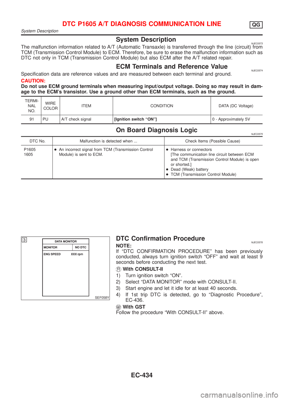
SEF058Y
DTC Confirmation ProcedureNJEC0576NOTE:
If ªDTC CONFIRMATION PROCEDUREº has been previously
conducted, always turn ignition switch ªOFFº and wait at least 9
seconds before conducting the next test.
With CONSULT-II
1) Turn ignition switch ªONº.
2) Select ªDATA MONITORº mode with CONSULT-II.
3) Start engine and let it idle for at least 40 seconds.
4) If 1st trip DTC is detected, go to ªDiagnostic Procedureº,
EC-436.
With GST
Follow the procedure ªWith CONSULT-IIº above.
DTC P1605 A/T DIAGNOSIS COMMUNICATION LINEQG
System Description
EC-434
Page 1159 of 2898
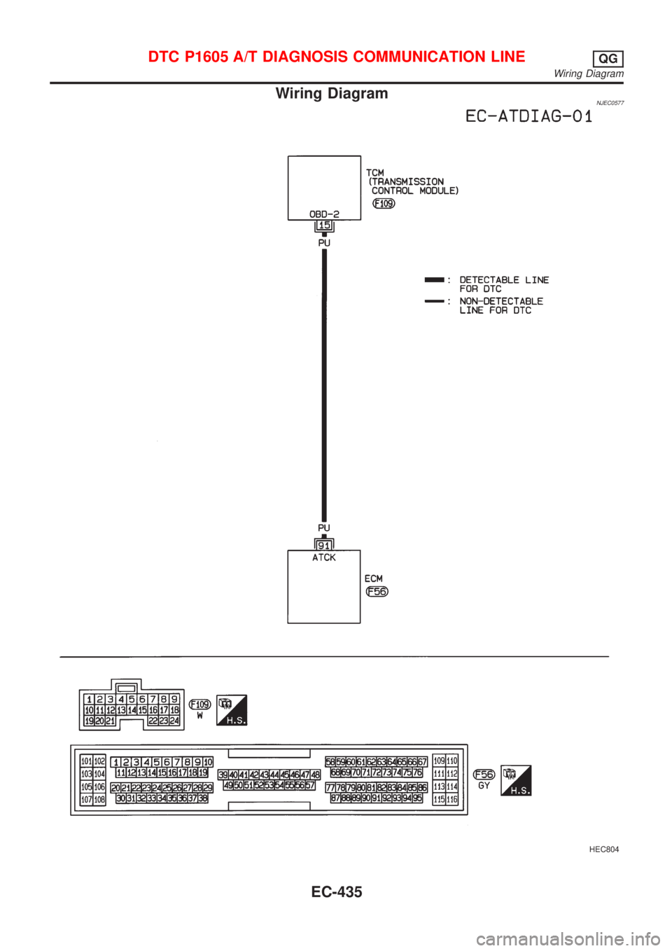
Wiring DiagramNJEC0577
HEC804
DTC P1605 A/T DIAGNOSIS COMMUNICATION LINEQG
Wiring Diagram
EC-435
Page 1160 of 2898
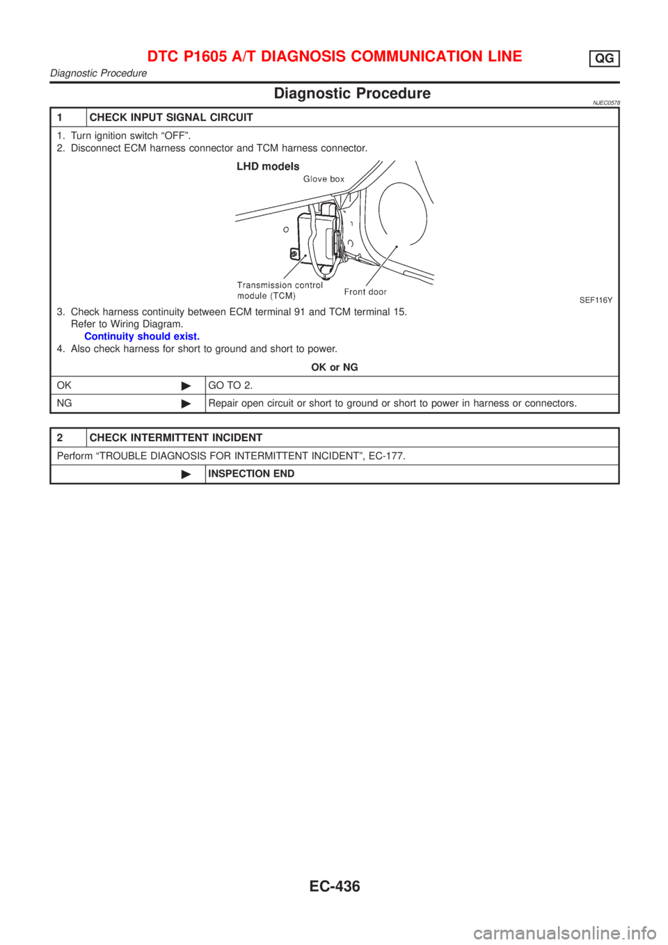
Diagnostic ProcedureNJEC0578
1 CHECK INPUT SIGNAL CIRCUIT
1. Turn ignition switch ªOFFº.
2. Disconnect ECM harness connector and TCM harness connector.
SEF116Y
3. Check harness continuity between ECM terminal 91 and TCM terminal 15.
Refer to Wiring Diagram.
Continuity should exist.
4. Also check harness for short to ground and short to power.
OK or NG
OK©GO TO 2.
NG©Repair open circuit or short to ground or short to power in harness or connectors.
2 CHECK INTERMITTENT INCIDENT
Perform ªTROUBLE DIAGNOSIS FOR INTERMITTENT INCIDENTº, EC-177.
©INSPECTION END
DTC P1605 A/T DIAGNOSIS COMMUNICATION LINEQG
Diagnostic Procedure
EC-436