NISSAN ALMERA 2001 Service Manual
ALMERA 2001
NISSAN
NISSAN
https://www.carmanualsonline.info/img/5/57348/w960_57348-0.png
NISSAN ALMERA 2001 Service Manual
Trending: sensor, wheel alignment, fuse, AUX, radio controls, Front brakes, phone
Page 1321 of 2898
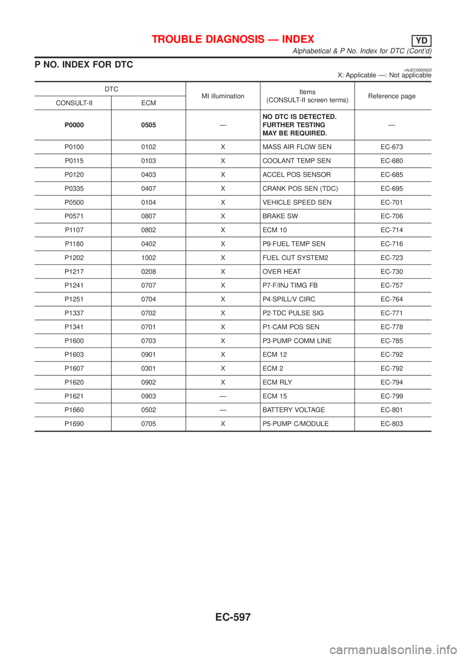
P NO. INDEX FOR DTC=NJEC0600S02X: Applicable Ð: Not applicable
DTC
MI illuminationItems
(CONSULT-II screen terms)Reference page
CONSULT-II ECM
P0000 0505ÐNO DTC IS DETECTED.
FURTHER TESTING
MAY BE REQUIRED.Ð
P0100 0102 X MASS AIR FLOW SEN EC-673
P0115 0103 X COOLANT TEMP SEN EC-680
P0120 0403 X ACCEL POS SENSOR EC-685
P0335 0407 X CRANK POS SEN (TDC) EC-695
P0500 0104 X VEHICLE SPEED SEN EC-701
P0571 0807 X BRAKE SW EC-706
P1107 0802 X ECM 10 EC-714
P1180 0402 X P9´FUEL TEMP SEN EC-716
P1202 1002 X FUEL CUT SYSTEM2 EC-723
P1217 0208 X OVER HEAT EC-730
P1241 0707 X P7´F/INJ TIMG FB EC-757
P1251 0704 X P4´SPILL/V CIRC EC-764
P1337 0702 X P2´TDC PULSE SIG EC-771
P1341 0701 X P1´CAM POS SEN EC-778
P1600 0703 X P3´PUMP COMM LINE EC-785
P1603 0901 X ECM 12 EC-792
P1607 0301 X ECM 2 EC-792
P1620 0902 X ECM RLY EC-794
P1621 0903 Ð ECM 15 EC-799
P1660 0502 Ð BATTERY VOLTAGE EC-801
P1690 0705 X P5´PUMP C/MODULE EC-803
TROUBLE DIAGNOSIS Ð INDEXYD
Alphabetical & P No. Index for DTC (Cont'd)
EC-597
Page 1322 of 2898
Supplemental Restraint System (SRS) ªAIR
BAGº and ªSEAT BELT PRE-TENSIONERº
NJEC0601The Supplemental Restraint System such as ªAIR BAGº and ªSEAT BELT PRE-TENSIONERº used along with
a seat belt, helps to reduce the risk or severity of injury to the driver and front passenger for certain types of
collision. The SRS system composition which is available to NISSAN MODEL N16 is as follows (The compo-
sition varies according to the destination and optional equipment.):
+For a frontal collision
The Supplemental Restraint System consists of driver air bag module (located in the center of the steer-
ing wheel), front passenger air bag module (located on the instrument panel on passenger side), front seat
belt pre-tensioners, a diagnosis sensor unit, warning lamp, wiring harness and spiral cable.
+For a side collision
The Supplemental Restraint System consists of front side air bag module (located in the outer side of front
seat), side air bag (satellite) sensor, diagnosis sensor unit (one of components of air bags for a frontal
collision), wiring harness, warning lamp (one of components of air bags for a frontal collision).
Information necessary to service the system safely is included in theRS sectionof this Service Manual.
WARNING:
+To avoid rendering the SRS inoperative, which could increase the risk of personal injury or death
in the event of a collision which would result in air bag inflation, all maintenance should be per-
formed by an authorized NISSAN dealer.
+Improper maintenance, including incorrect removal and installation of the SRS, can lead to per-
sonal injury caused by unintentional activation of the system. For removal of Spiral Cable and Air
Bag Module, see the RS section.
+Do not use electrical test equipment on any circuit related to the SRS unless instructed to in this
Service Manual. SRS wiring harness can be identified by yellow harness connector.
PRECAUTIONSYD
Supplemental Restraint System (SRS) ªAIR BAGº and ªSEAT BELT PRE-TENSIONERº
EC-598
Page 1323 of 2898
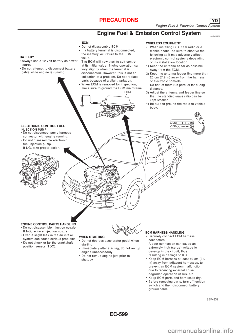
Engine Fuel & Emission Control SystemNJEC0602
SEF433Z
PRECAUTIONSYD
Engine Fuel & Emission Control System
EC-599
Page 1324 of 2898
SEF289H
PrecautionsNJEC0603+Before connecting or disconnecting the ECM harness
connector, turn ignition switch OFF and disconnect nega-
tive battery terminal. Failure to do so may damage the
ECM because battery voltage is applied to ECM even if
ignition switch is turned off.
SEF881Y
+When connecting ECM harness connectors, push in both
sides of the connector until you hear a click. Maneuver the
lever until you hear the three connectors on the inside
click. Refer to the figure at left.
SEF291H
+When connecting or disconnecting pin connectors into or
from ECM, take care not to damage pin terminals (bend or
break).
Make sure that there are not any bends or breaks on ECM
pin terminal, when connecting pin connectors.
MEF040D
+Before replacing ECM, perform Terminals and Reference
Value inspection and make sure ECM functions properly.
Refer to EC-659.
SAT652J
+If MI illuminates or blinks irregularly when engine is
running, water may have accumulated in fuel filter. Drain
water from fuel filter. If this does not correct the problem,
perform specified trouble diagnostic procedures.
+After performing each TROUBLE DIAGNOSIS, perform
ªDTC Confirmation Procedureº or ªOverall Function
Checkº.
The DTC should not be displayed in the ª DTC Confirma-
tion Procedureº if the repair is completed. The ªOverall
Function Checkº should be a good result if the repair is
completed.
PRECAUTIONSYD
Precautions
EC-600
Page 1325 of 2898
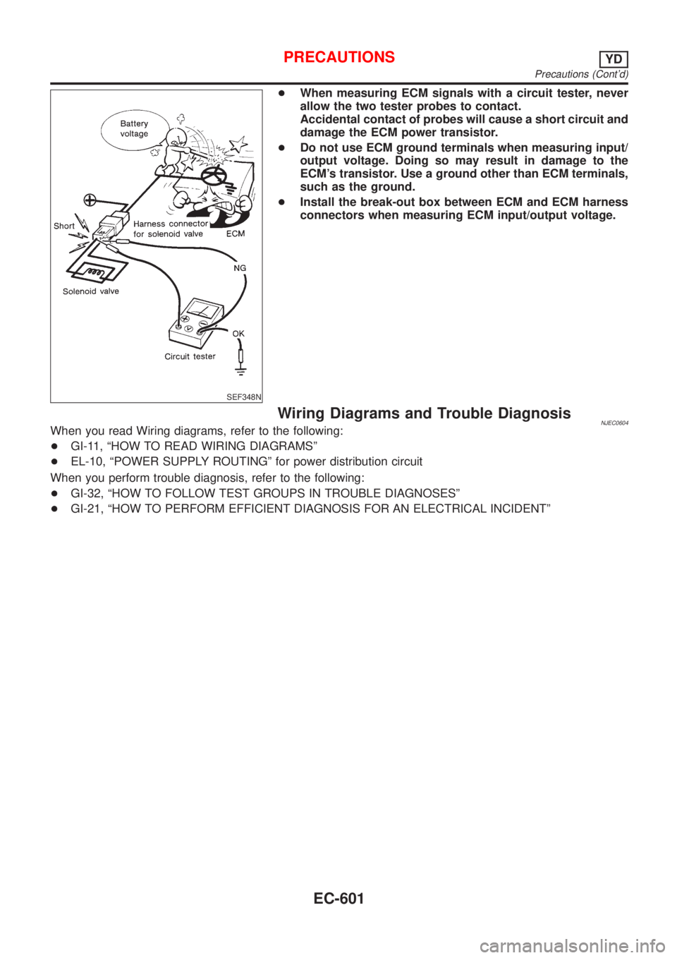
SEF348N
+When measuring ECM signals with a circuit tester, never
allow the two tester probes to contact.
Accidental contact of probes will cause a short circuit and
damage the ECM power transistor.
+Do not use ECM ground terminals when measuring input/
output voltage. Doing so may result in damage to the
ECM's transistor. Use a ground other than ECM terminals,
such as the ground.
+Install the break-out box between ECM and ECM harness
connectors when measuring ECM input/output voltage.
Wiring Diagrams and Trouble DiagnosisNJEC0604When you read Wiring diagrams, refer to the following:
+GI-11, ªHOW TO READ WIRING DIAGRAMSº
+EL-10, ªPOWER SUPPLY ROUTINGº for power distribution circuit
When you perform trouble diagnosis, refer to the following:
+GI-32, ªHOW TO FOLLOW TEST GROUPS IN TROUBLE DIAGNOSESº
+GI-21, ªHOW TO PERFORM EFFICIENT DIAGNOSIS FOR AN ELECTRICAL INCIDENTº
PRECAUTIONSYD
Precautions (Cont'd)
EC-601
Page 1326 of 2898
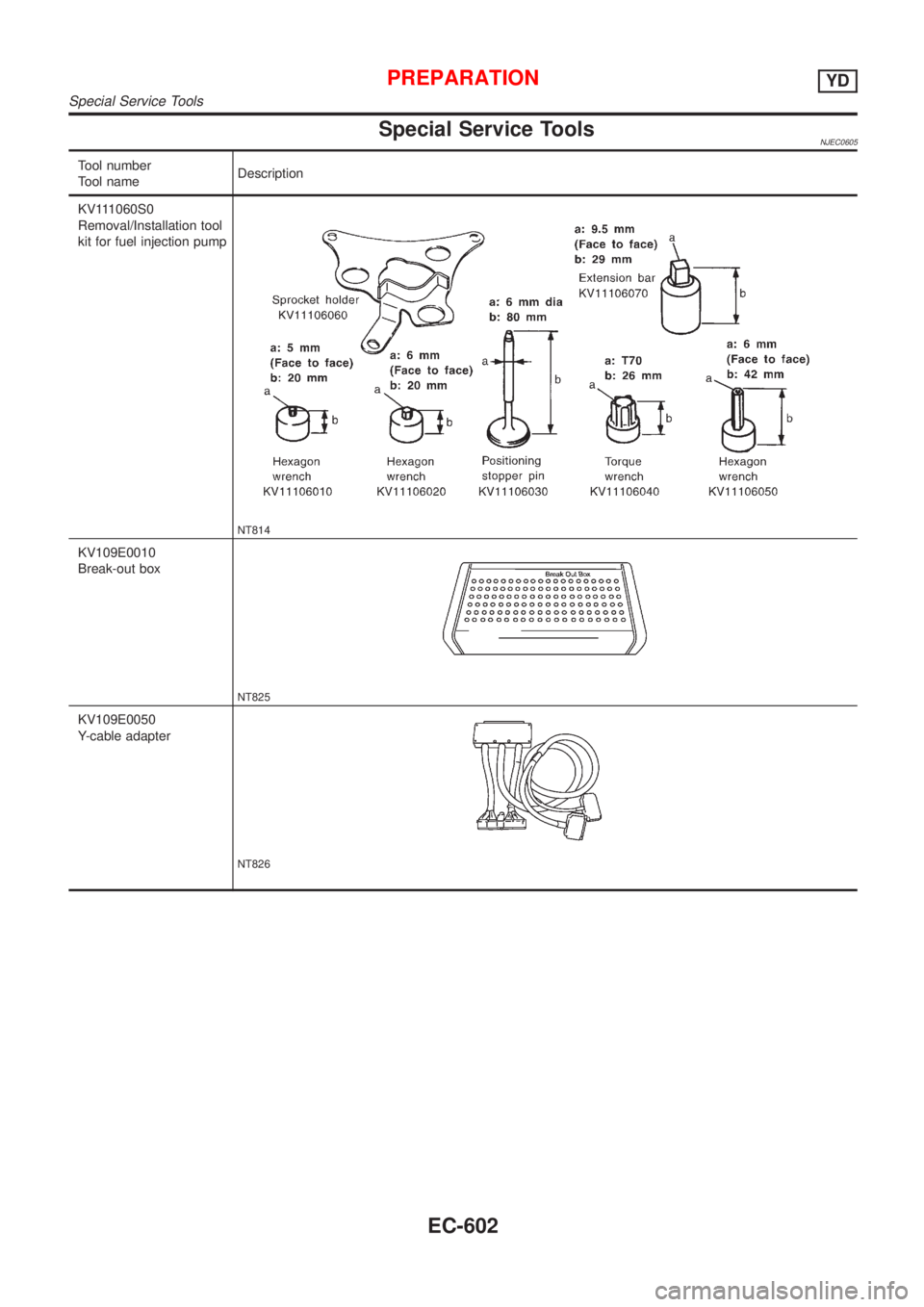
Special Service ToolsNJEC0605
Tool number
Tool nameDescription
KV111060S0
Removal/Installation tool
kit for fuel injection pump
NT814
KV109E0010
Break-out box
NT825
KV109E0050
Y-cable adapter
NT826
PREPARATIONYD
Special Service Tools
EC-602
Page 1327 of 2898
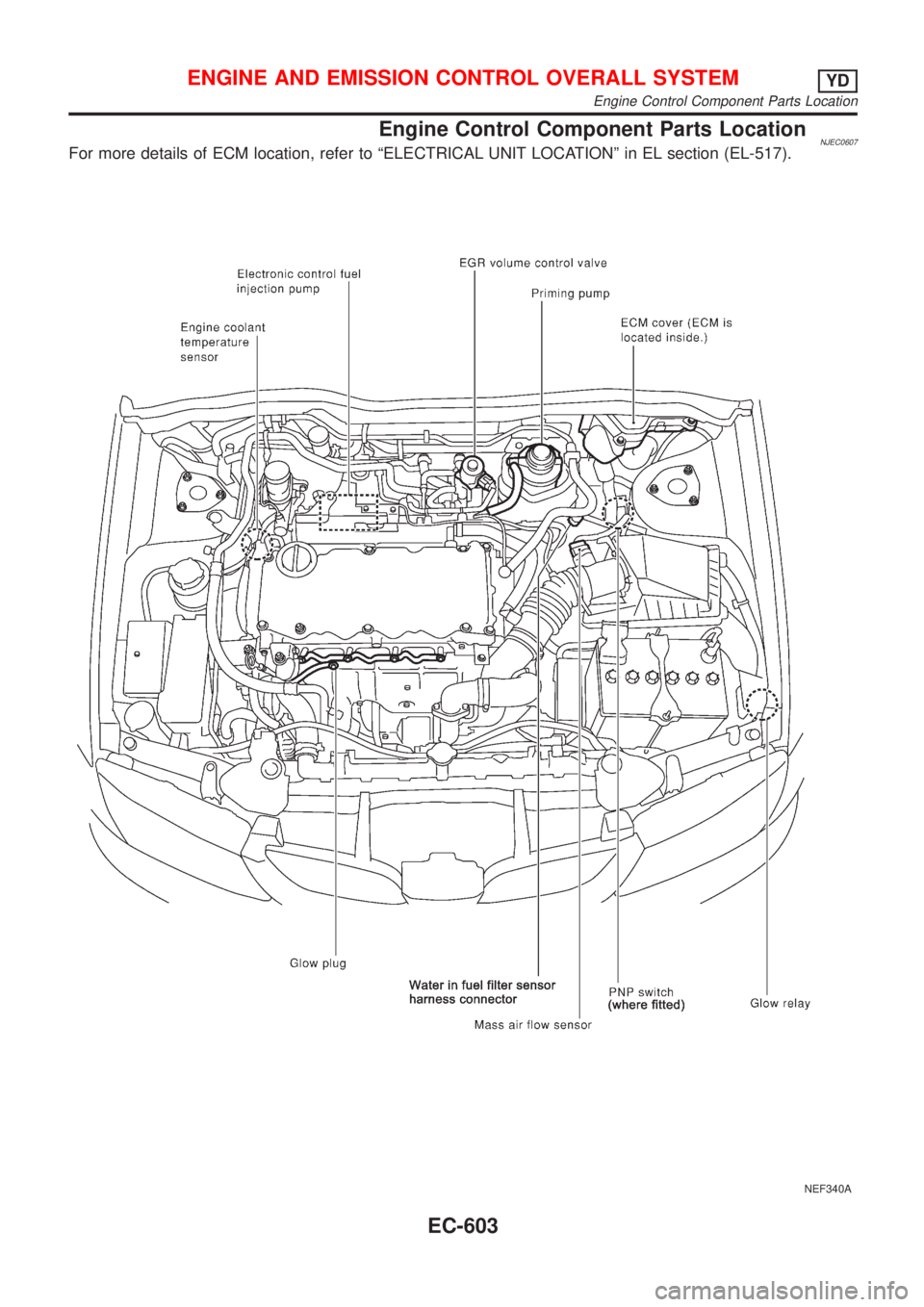
Engine Control Component Parts LocationNJEC0607For more details of ECM location, refer to ªELECTRICAL UNIT LOCATIONº in EL section (EL-517).
NEF340A
ENGINE AND EMISSION CONTROL OVERALL SYSTEMYD
Engine Control Component Parts Location
EC-603
Page 1328 of 2898
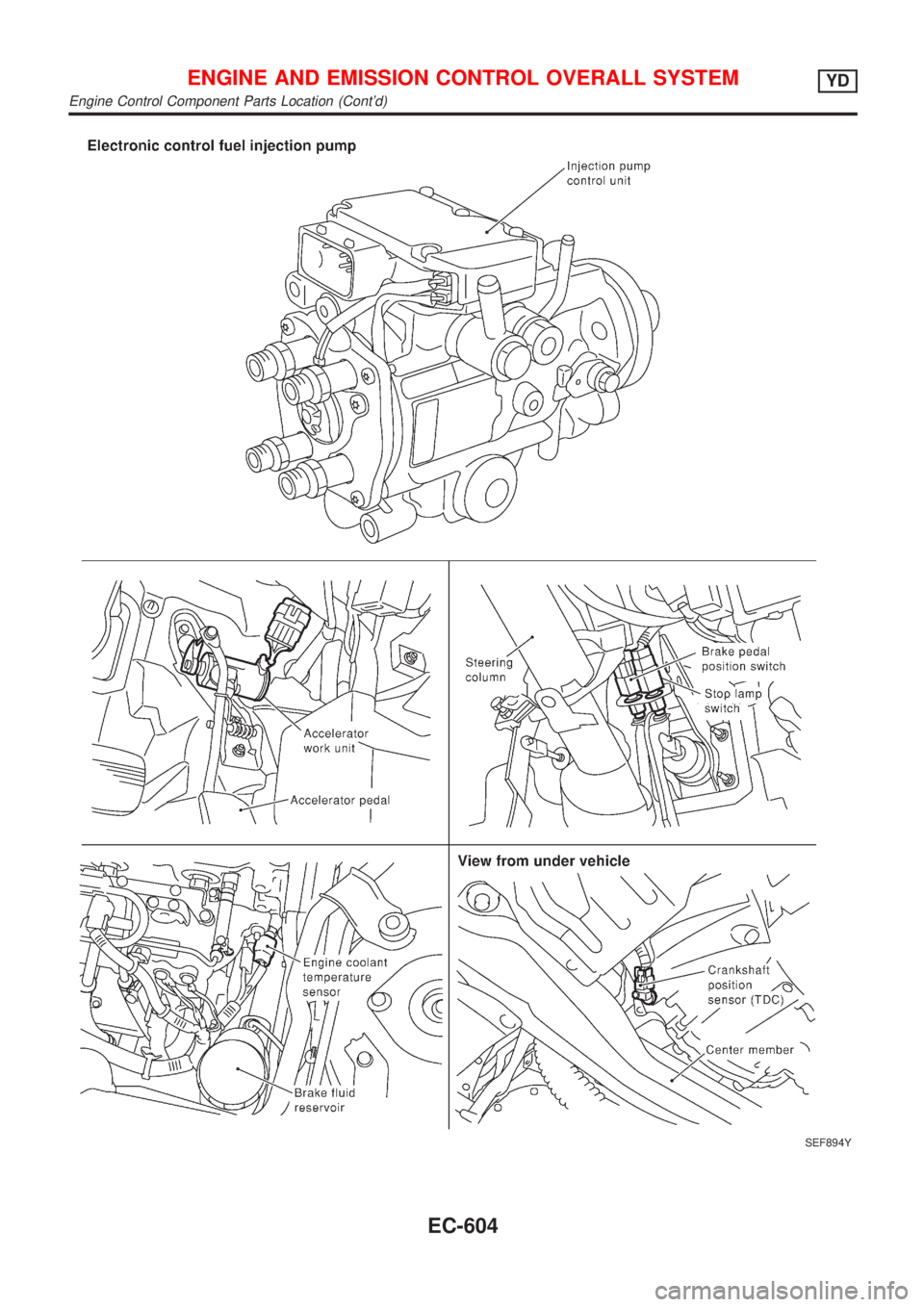
SEF894Y
ENGINE AND EMISSION CONTROL OVERALL SYSTEMYD
Engine Control Component Parts Location (Cont'd)
EC-604
Page 1329 of 2898
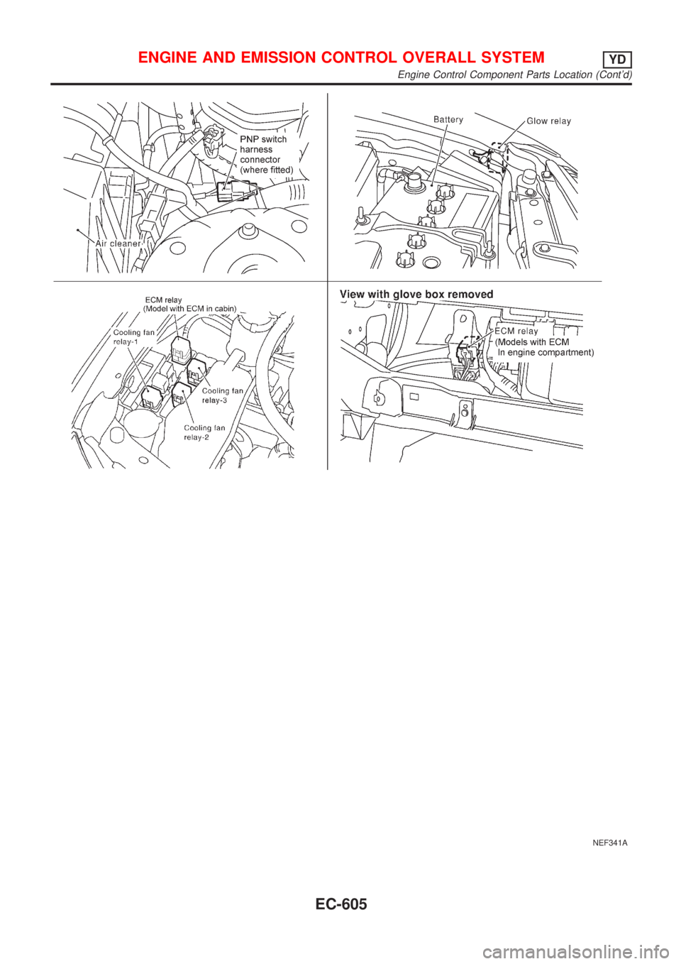
NEF341A
ENGINE AND EMISSION CONTROL OVERALL SYSTEMYD
Engine Control Component Parts Location (Cont'd)
EC-605
Page 1330 of 2898
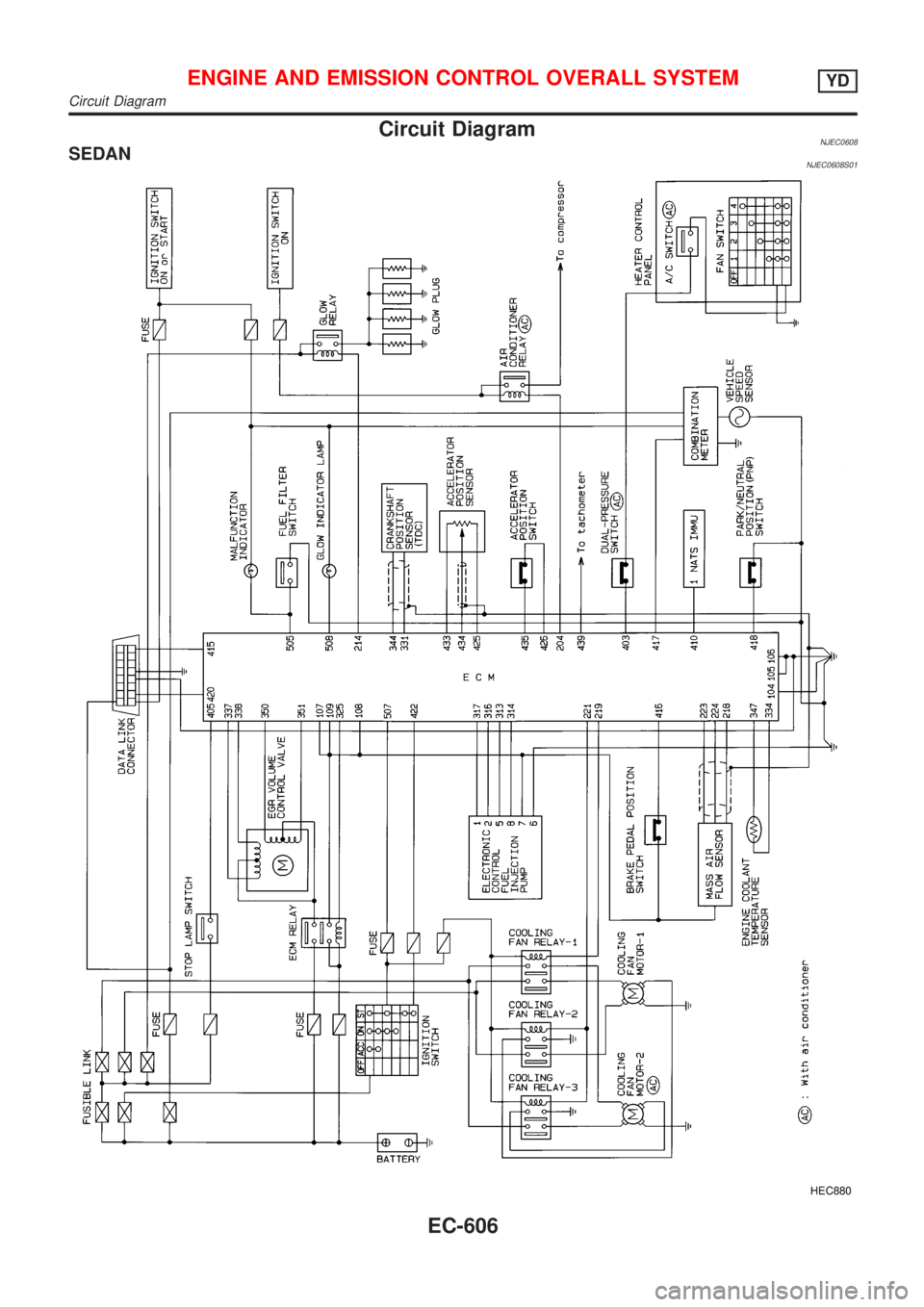
Circuit DiagramNJEC0608SEDANNJEC0608S01
HEC880
ENGINE AND EMISSION CONTROL OVERALL SYSTEMYD
Circuit Diagram
EC-606
Trending: open hood, load capacity, washer fluid, height, belt, Ignition system, turn signal bulb


