NISSAN ALMERA 2001 Service Manual
Manufacturer: NISSAN, Model Year: 2001, Model line: ALMERA, Model: NISSAN ALMERA 2001Pages: 2898, PDF Size: 60.76 MB
Page 1311 of 2898
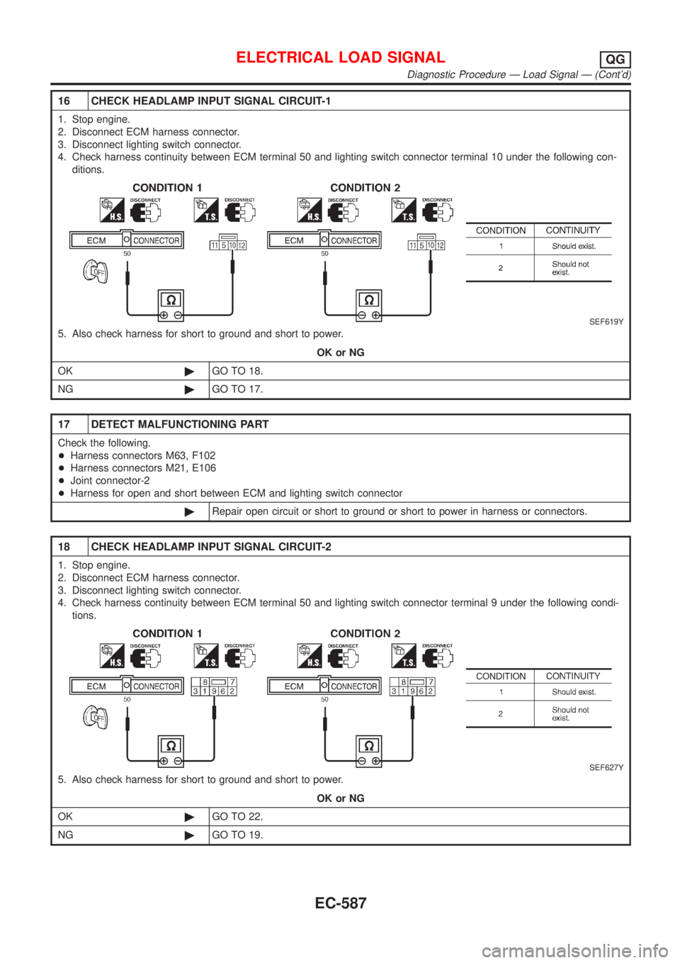
16 CHECK HEADLAMP INPUT SIGNAL CIRCUIT-1
1. Stop engine.
2. Disconnect ECM harness connector.
3. Disconnect lighting switch connector.
4. Check harness continuity between ECM terminal 50 and lighting switch connector terminal 10 under the following con-
ditions.
SEF619Y
5. Also check harness for short to ground and short to power.
OK or NG
OK©GO TO 18.
NG©GO TO 17.
17 DETECT MALFUNCTIONING PART
Check the following.
+Harness connectors M63, F102
+Harness connectors M21, E106
+Joint connector-2
+Harness for open and short between ECM and lighting switch connector
©Repair open circuit or short to ground or short to power in harness or connectors.
18 CHECK HEADLAMP INPUT SIGNAL CIRCUIT-2
1. Stop engine.
2. Disconnect ECM harness connector.
3. Disconnect lighting switch connector.
4. Check harness continuity between ECM terminal 50 and lighting switch connector terminal 9 under the following condi-
tions.
SEF627Y
5. Also check harness for short to ground and short to power.
OK or NG
OK©GO TO 22.
NG©GO TO 19.
ELECTRICAL LOAD SIGNALQG
Diagnostic Procedure Ð Load Signal Ð (Cont'd)
EC-587
Page 1312 of 2898
19 DETECT MALFUNCTIONING PART
Check the following.
+Harness connectors M63, F102
+Harness connectors M79, E118
+Diode M110
+Joint connector-2
+Harness for open and short between ECM and lighting switch connector
©Repair open circuit or short to ground or short to power in harness or connectors.
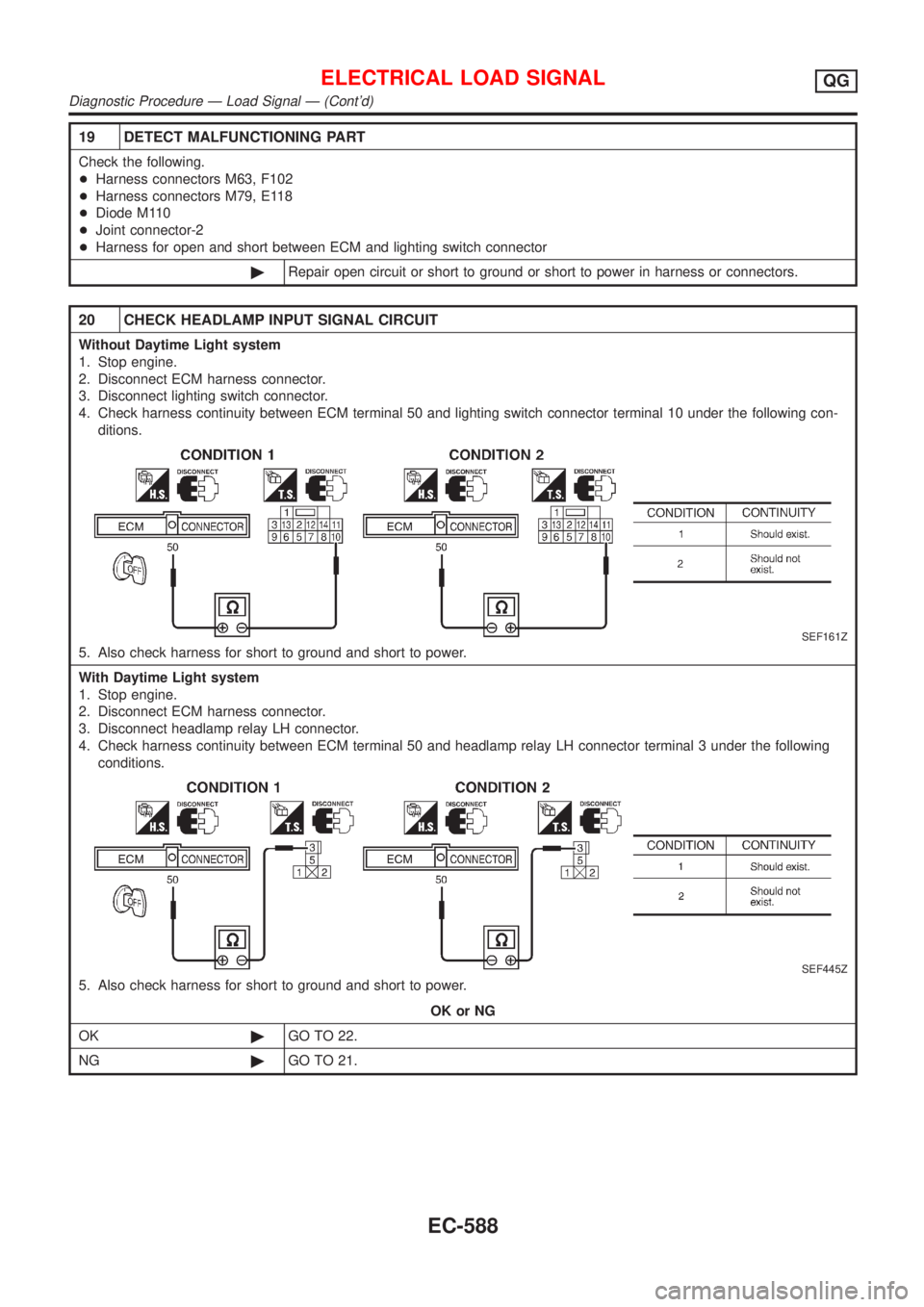
20 CHECK HEADLAMP INPUT SIGNAL CIRCUIT
Without Daytime Light system
1. Stop engine.
2. Disconnect ECM harness connector.
3. Disconnect lighting switch connector.
4. Check harness continuity between ECM terminal 50 and lighting switch connector terminal 10 under the following con-
ditions.
SEF161Z
5. Also check harness for short to ground and short to power.
With Daytime Light system
1. Stop engine.
2. Disconnect ECM harness connector.
3. Disconnect headlamp relay LH connector.
4. Check harness continuity between ECM terminal 50 and headlamp relay LH connector terminal 3 under the following
conditions.
SEF445Z
5. Also check harness for short to ground and short to power.
OK or NG
OK©GO TO 22.
NG©GO TO 21.
ELECTRICAL LOAD SIGNALQG
Diagnostic Procedure Ð Load Signal Ð (Cont'd)
EC-588
Page 1313 of 2898
21 DETECT MALFUNCTIONING PART
Check the following.
+Harness connectors M63, F102
+Harness connectors M159, F174
+Diode E177
+Harness for open and short between ECM and lighting switch connector
©Repair open circuit or short to ground or short to power in harness or connectors.
22 CHECK INTERMITTENT INCIDENT
Perform ªTROUBLE DIAGNOSIS FOR INTERMITTENT INCIDENTº, EC-177.
©INSPECTION END
Diagnostic Procedure Ð Heater Control Panel
(Fan Switch) Ð
NJEC0585
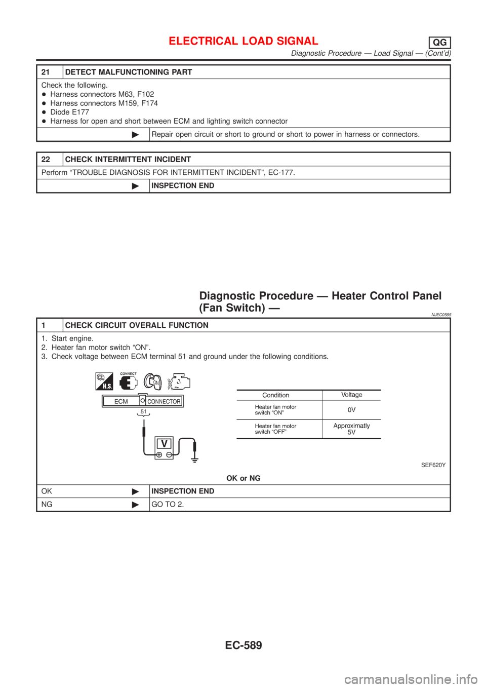
1 CHECK CIRCUIT OVERALL FUNCTION
1. Start engine.
2. Heater fan motor switch ªONº.
3. Check voltage between ECM terminal 51 and ground under the following conditions.
SEF620Y
OK or NG
OK©INSPECTION END
NG©GO TO 2.
ELECTRICAL LOAD SIGNALQG
Diagnostic Procedure Ð Load Signal Ð (Cont'd)
EC-589
Page 1314 of 2898
2 CHECK INPUT SIGNAL CIRCUIT
1. Stop engine.
2. Disconnect ECM harness connector.
3. Disconnect heater control panel fan switch harness connector.
4. Check harness continuity between ECM terminal 51 and heater fan switch harness connector terminal 18.
Refer to wiring diagram.
Continuity should exist.
5. Also check harness for short to ground and short to power.
OK or NG
OK©Refer to HA-48, ªBLOWER MOTORº.
NG©GO TO 3.
3 DETECT MALFUNCTIONING PART
Check the following.
+Harness connectors M94, F106 (Sedan)
+Harness connectors M73, F111 or M169, F113 (Hatchback)
+Harness for open and short between ECM and heater fan motor switch
©Repair open circuit or short to ground or short to power in harness or connectors.
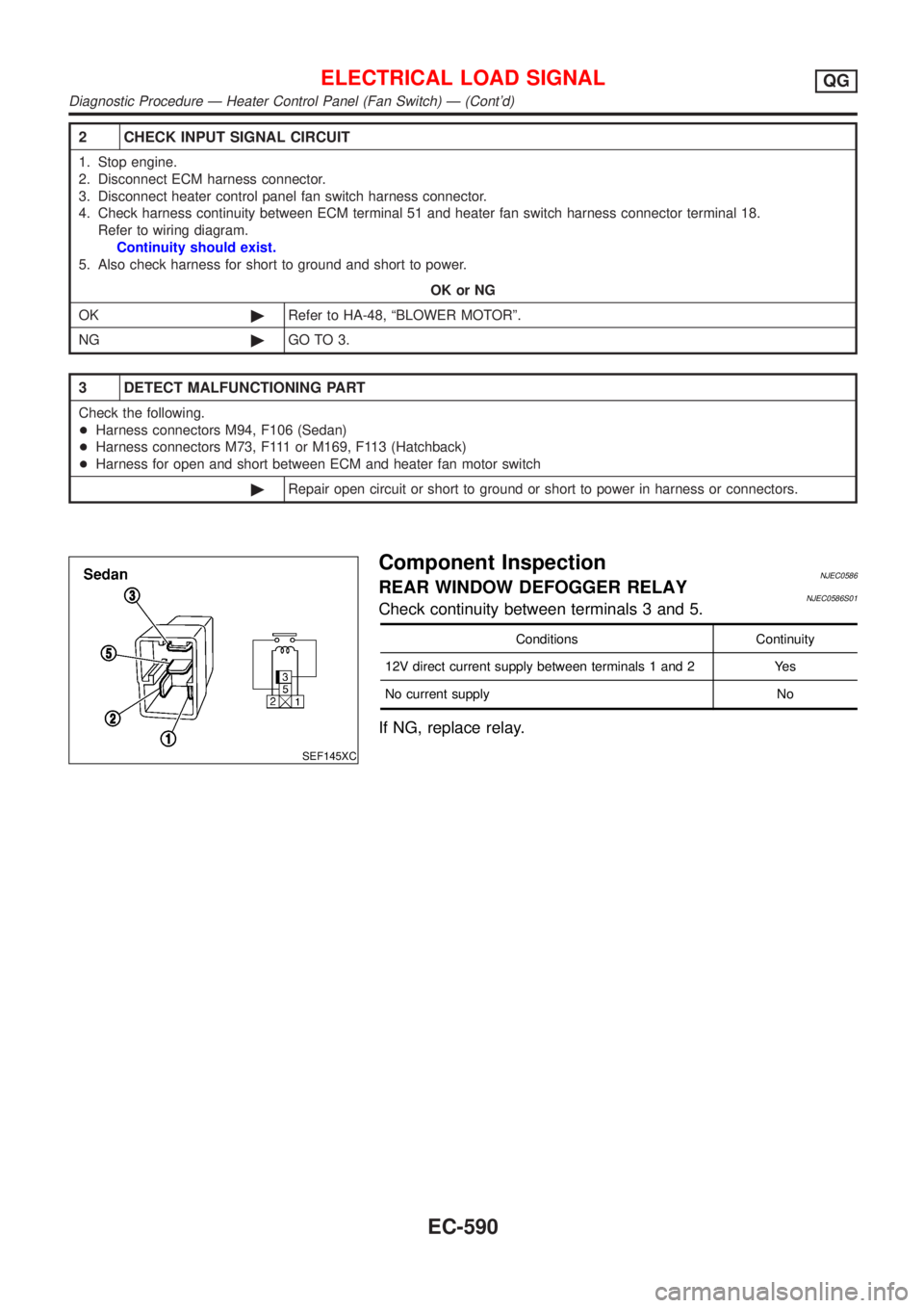
SEF145XC
Component InspectionNJEC0586REAR WINDOW DEFOGGER RELAYNJEC0586S01Check continuity between terminals 3 and 5.
Conditions Continuity
12V direct current supply between terminals 1 and 2 Yes
No current supply No
If NG, replace relay.
ELECTRICAL LOAD SIGNALQG
Diagnostic Procedure Ð Heater Control Panel (Fan Switch) Ð (Cont'd)
EC-590
Page 1315 of 2898

Wiring DiagramNJEC0466SEDAN MODELS AND HATCHBACK MODELS WITH
ECM IN ENGINE COMPARTMENT
NJEC0466S01
HEC894
MI & DATA LINK CONNECTORSQG
Wiring Diagram
EC-591
Page 1316 of 2898
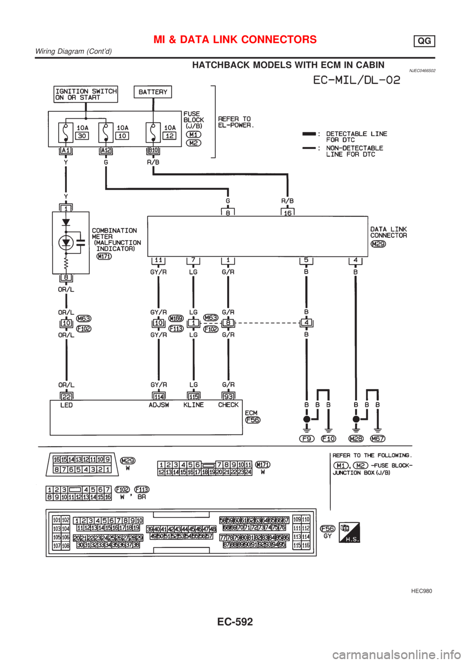
HATCHBACK MODELS WITH ECM IN CABINNJEC0466S02
HEC980
MI & DATA LINK CONNECTORSQG
Wiring Diagram (Cont'd)
EC-592
Page 1317 of 2898
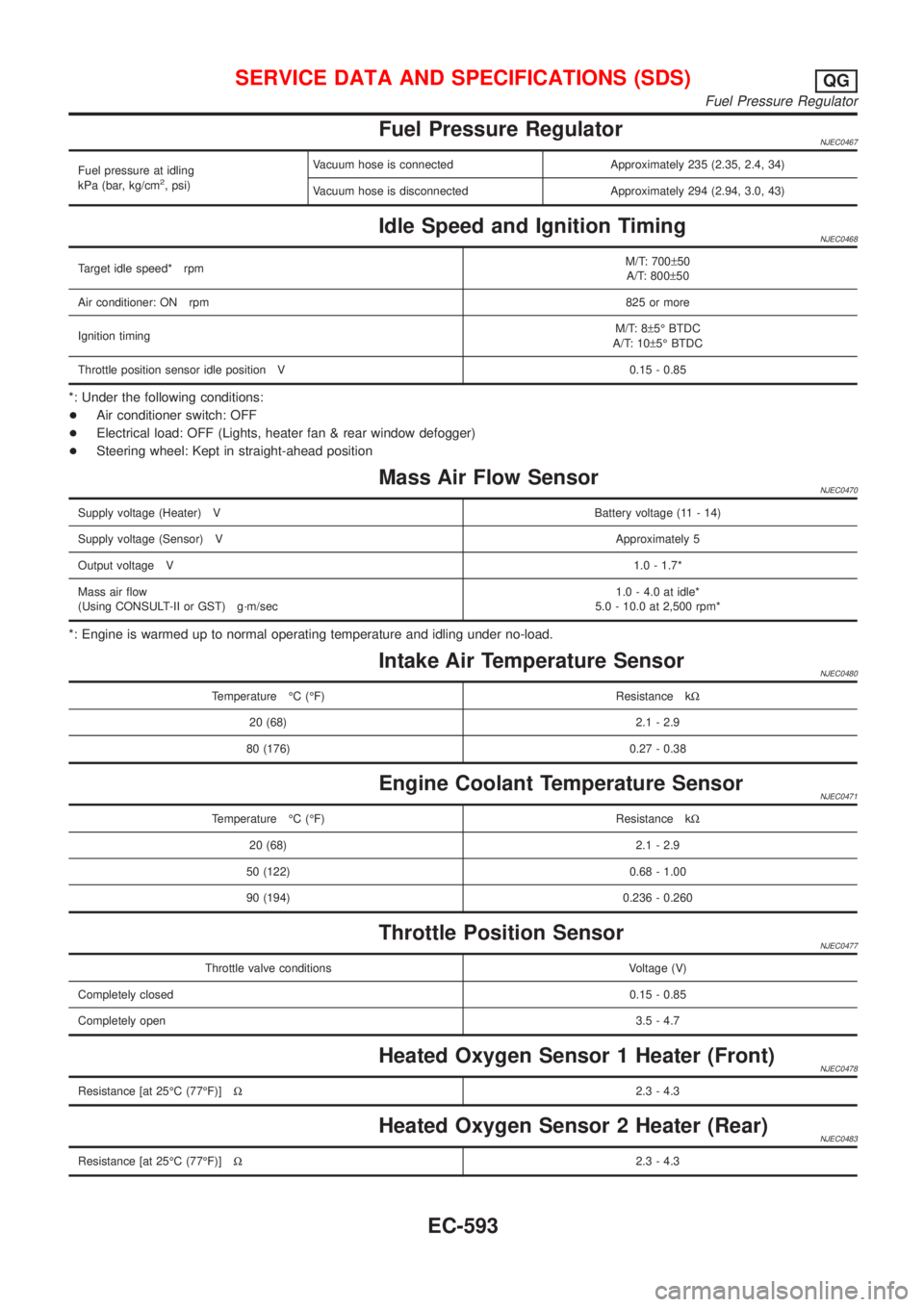
Fuel Pressure RegulatorNJEC0467
Fuel pressure at idling
kPa (bar, kg/cm2, psi)Vacuum hose is connected Approximately 235 (2.35, 2.4, 34)
Vacuum hose is disconnected Approximately 294 (2.94, 3.0, 43)
Idle Speed and Ignition TimingNJEC0468
Target idle speed* rpmM/T: 700±50
A/T: 800±50
Air conditioner: ON rpm825 or more
Ignition timingM/T: 8±5É BTDC
A/T: 10±5É BTDC
Throttle position sensor idle position V 0.15 - 0.85
*: Under the following conditions:
+Air conditioner switch: OFF
+Electrical load: OFF (Lights, heater fan & rear window defogger)
+Steering wheel: Kept in straight-ahead position
Mass Air Flow SensorNJEC0470
Supply voltage (Heater) VBattery voltage (11 - 14)
Supply voltage (Sensor) VApproximately 5
Output voltage V1.0 - 1.7*
Mass air flow
(Using CONSULT-II or GST) g´m/sec1.0 - 4.0 at idle*
5.0 - 10.0 at 2,500 rpm*
*: Engine is warmed up to normal operating temperature and idling under no-load.
Intake Air Temperature SensorNJEC0480
Temperature ÉC (ÉF) Resistance kW
20 (68) 2.1 - 2.9
80 (176) 0.27 - 0.38
Engine Coolant Temperature SensorNJEC0471
Temperature ÉC (ÉF) Resistance kW
20 (68) 2.1 - 2.9
50 (122) 0.68 - 1.00
90 (194) 0.236 - 0.260
Throttle Position SensorNJEC0477
Throttle valve conditions Voltage (V)
Completely closed0.15 - 0.85
Completely open3.5 - 4.7
Heated Oxygen Sensor 1 Heater (Front)NJEC0478
Resistance [at 25ÉC (77ÉF)]W2.3 - 4.3
Heated Oxygen Sensor 2 Heater (Rear)NJEC0483
Resistance [at 25ÉC (77ÉF)]W2.3 - 4.3
SERVICE DATA AND SPECIFICATIONS (SDS)QG
Fuel Pressure Regulator
EC-593
Page 1318 of 2898
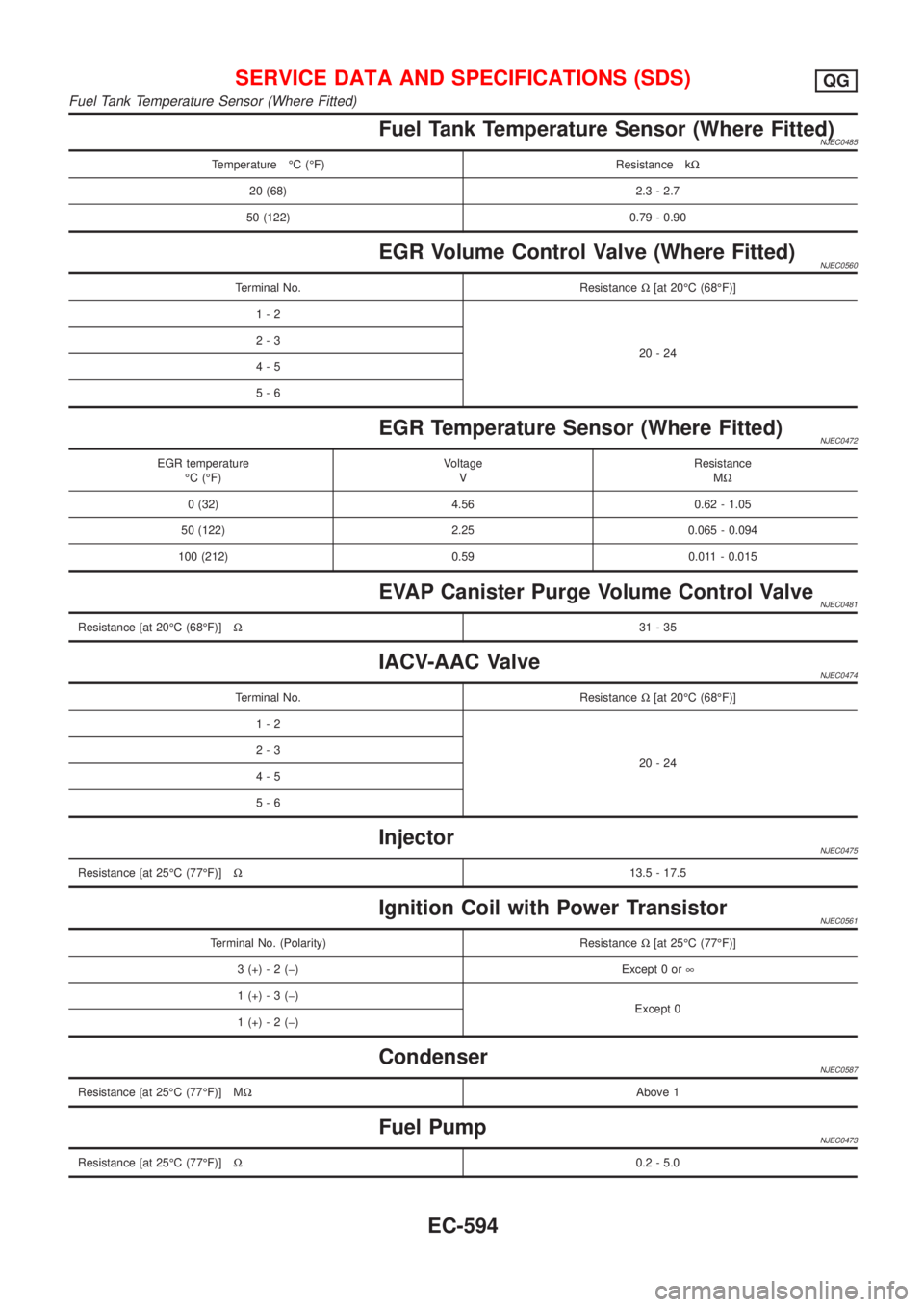
Fuel Tank Temperature Sensor (Where Fitted)NJEC0485
Temperature ÉC (ÉF) Resistance kW
20 (68) 2.3 - 2.7
50 (122) 0.79 - 0.90
EGR Volume Control Valve (Where Fitted)NJEC0560
Terminal No. ResistanceW[at 20ÉC (68ÉF)]
1-2
20-24 2-3
4-5
5-6
EGR Temperature Sensor (Where Fitted)NJEC0472
EGR temperature
ÉC (ÉF)Voltage
VResistance
MW
0 (32) 4.56 0.62 - 1.05
50 (122) 2.25 0.065 - 0.094
100 (212) 0.59 0.011 - 0.015
EVAP Canister Purge Volume Control ValveNJEC0481
Resistance [at 20ÉC (68ÉF)]W31-35
IACV-AAC ValveNJEC0474
Terminal No. ResistanceW[at 20ÉC (68ÉF)]
1-2
20-24 2-3
4-5
5-6
InjectorNJEC0475
Resistance [at 25ÉC (77ÉF)]W13.5 - 17.5
Ignition Coil with Power TransistorNJEC0561
Terminal No. (Polarity) ResistanceW[at 25ÉC (77ÉF)]
3 (+) - 2 (þ) Except 0 or¥
1 (+) - 3 (þ)
Except 0
1 (+) - 2 (þ)
CondenserNJEC0587
Resistance [at 25ÉC (77ÉF)] MWAbove 1
Fuel PumpNJEC0473
Resistance [at 25ÉC (77ÉF)]W0.2 - 5.0
SERVICE DATA AND SPECIFICATIONS (SDS)QG
Fuel Tank Temperature Sensor (Where Fitted)
EC-594
Page 1319 of 2898

Crankshaft Position Sensor (POS)NJEC0558Refer to ªComponent Inspectionº, EC-334.
Camshaft Position Sensor (PHASE)NJEC0559Refer to ªComponent Inspectionº, EC-342.
SERVICE DATA AND SPECIFICATIONS (SDS)QG
Crankshaft Position Sensor (POS)
EC-595
Page 1320 of 2898
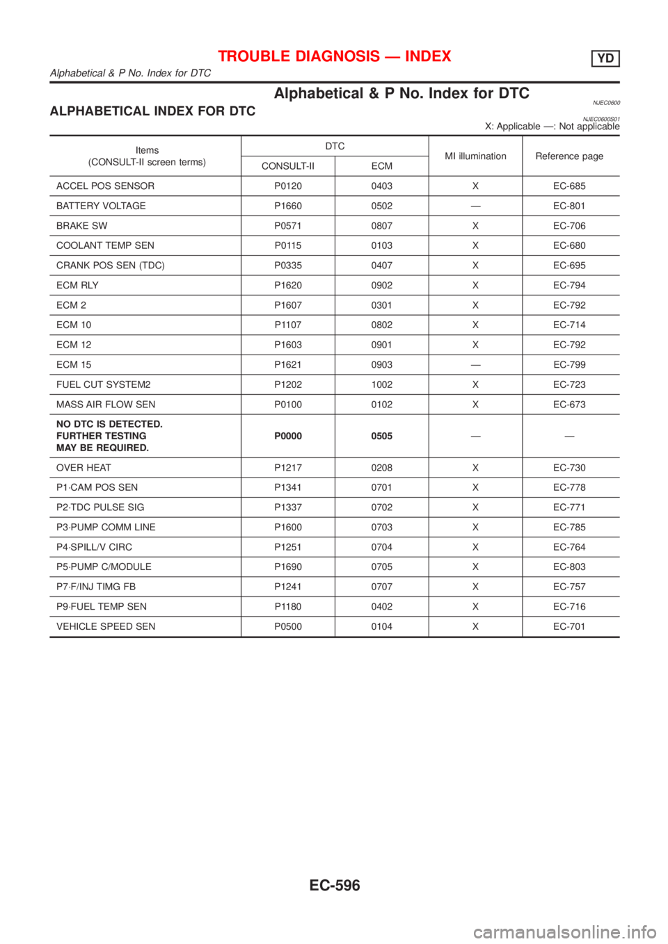
Alphabetical & P No. Index for DTCNJEC0600ALPHABETICAL INDEX FOR DTCNJEC0600S01X: Applicable Ð: Not applicable
Items
(CONSULT-II screen terms)DTC
MI illumination Reference page
CONSULT-II ECM
ACCEL POS SENSOR P0120 0403 X EC-685
BATTERY VOLTAGE P1660 0502 Ð EC-801
BRAKE SW P0571 0807 X EC-706
COOLANT TEMP SEN P0115 0103 X EC-680
CRANK POS SEN (TDC) P0335 0407 X EC-695
ECM RLY P1620 0902 X EC-794
ECM 2 P1607 0301 X EC-792
ECM 10 P1107 0802 X EC-714
ECM 12 P1603 0901 X EC-792
ECM 15 P1621 0903 Ð EC-799
FUEL CUT SYSTEM2 P1202 1002 X EC-723
MASS AIR FLOW SEN P0100 0102 X EC-673
NO DTC IS DETECTED.
FURTHER TESTING
MAY BE REQUIRED.P0000 0505ÐÐ
OVER HEAT P1217 0208 X EC-730
P1´CAM POS SEN P1341 0701 X EC-778
P2´TDC PULSE SIG P1337 0702 X EC-771
P3´PUMP COMM LINE P1600 0703 X EC-785
P4´SPILL/V CIRC P1251 0704 X EC-764
P5´PUMP C/MODULE P1690 0705 X EC-803
P7´F/INJ TIMG FB P1241 0707 X EC-757
P9´FUEL TEMP SEN P1180 0402 X EC-716
VEHICLE SPEED SEN P0500 0104 X EC-701
TROUBLE DIAGNOSIS Ð INDEXYD
Alphabetical & P No. Index for DTC
EC-596