NISSAN ALMERA 2001 Service Manual
Manufacturer: NISSAN, Model Year: 2001, Model line: ALMERA, Model: NISSAN ALMERA 2001Pages: 2898, PDF Size: 60.76 MB
Page 1391 of 2898

WIRING DIAGRAMNJEC0640Sedan Models and Hatchback Models with ECM in Engine CompartmentNJEC0640S01
HEC881
TROUBLE DIAGNOSIS FOR POWER SUPPLYYD
Main Power Supply and Ground Circuit (Cont'd)
EC-667
Page 1392 of 2898
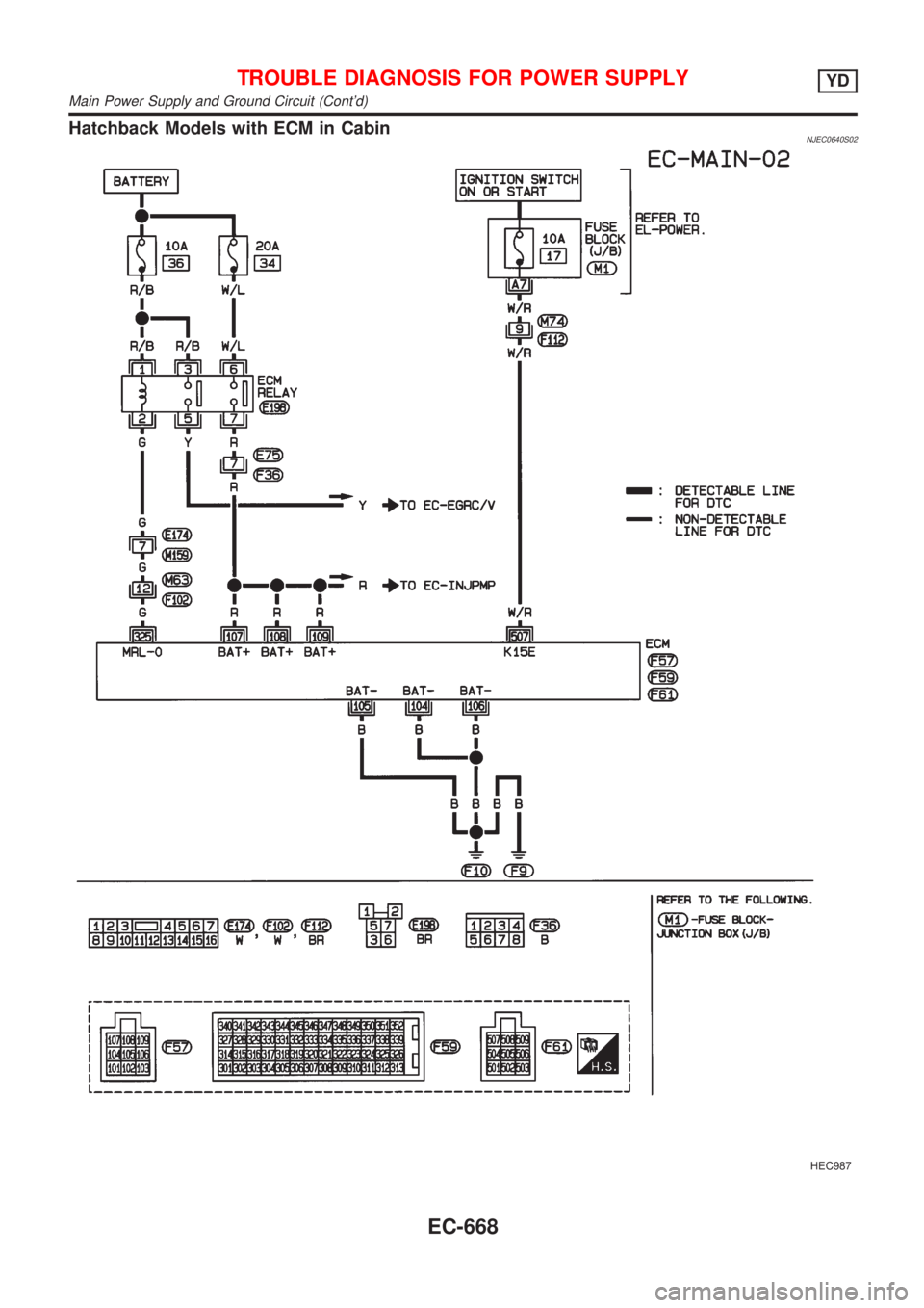
Hatchback Models with ECM in CabinNJEC0640S02
HEC987
TROUBLE DIAGNOSIS FOR POWER SUPPLYYD
Main Power Supply and Ground Circuit (Cont'd)
EC-668
Page 1393 of 2898
DIAGNOSTIC PROCEDURENJEC0641
1 INSPECTION START
Start engine.
Is engine running?
YesorNo
Ye s©GO TO 13.
No©GO TO 2.
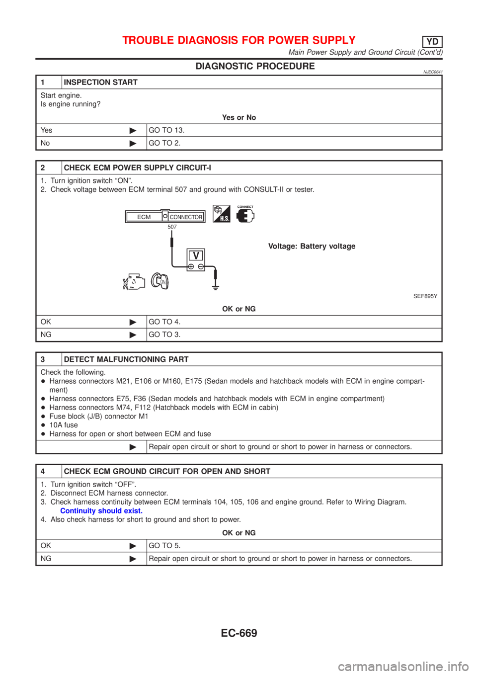
2 CHECK ECM POWER SUPPLY CIRCUIT-I
1. Turn ignition switch ªONº.
2. Check voltage between ECM terminal 507 and ground with CONSULT-II or tester.
SEF895Y
OK or NG
OK©GO TO 4.
NG©GO TO 3.
3 DETECT MALFUNCTIONING PART
Check the following.
+Harness connectors M21, E106 or M160, E175 (Sedan models and hatchback models with ECM in engine compart-
ment)
+Harness connectors E75, F36 (Sedan models and hatchback models with ECM in engine compartment)
+Harness connectors M74, F112 (Hatchback models with ECM in cabin)
+Fuse block (J/B) connector M1
+10A fuse
+Harness for open or short between ECM and fuse
©Repair open circuit or short to ground or short to power in harness or connectors.
4 CHECK ECM GROUND CIRCUIT FOR OPEN AND SHORT
1. Turn ignition switch ªOFFº.
2. Disconnect ECM harness connector.
3. Check harness continuity between ECM terminals 104, 105, 106 and engine ground. Refer to Wiring Diagram.
Continuity should exist.
4. Also check harness for short to ground and short to power.
OK or NG
OK©GO TO 5.
NG©Repair open circuit or short to ground or short to power in harness or connectors.
TROUBLE DIAGNOSIS FOR POWER SUPPLYYD
Main Power Supply and Ground Circuit (Cont'd)
EC-669
Page 1394 of 2898
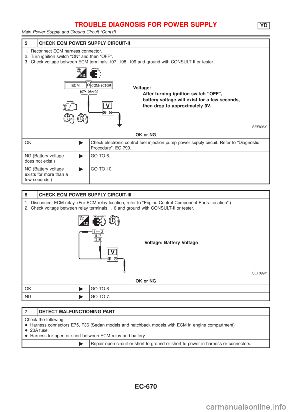
5 CHECK ECM POWER SUPPLY CIRCUIT-II
1. Reconnect ECM harness connector.
2. Turn ignition switch ªONº and then ªOFFº.
3. Check voltage between ECM terminals 107, 108, 109 and ground with CONSULT-II or tester.
SEF896Y
OK or NG
OK©Check electronic control fuel injection pump power supply circuit. Refer to ªDiagnostic
Procedureº, EC-790.
NG (Battery voltage
does not exist.)©GO TO 6.
NG (Battery voltage
exists for more than a
few seconds.)©GO TO 10.
6 CHECK ECM POWER SUPPLY CIRCUIT-III
1. Disconnect ECM relay. (For ECM relay location, refer to ªEngine Control Component Parts Locationº.)
2. Check voltage between relay terminals 1, 6 and ground with CONSULT-II or tester.
SEF399Y
OK or NG
OK©GO TO 8.
NG©GO TO 7.
7 DETECT MALFUNCTIONING PART
Check the following.
+Harness connectors E75, F36 (Sedan models and hatchback models with ECM in engine compartment)
+20A fuse
+Harness for open or short between ECM relay and battery
©Repair open circuit or short to ground or short to power in harness or connectors.
TROUBLE DIAGNOSIS FOR POWER SUPPLYYD
Main Power Supply and Ground Circuit (Cont'd)
EC-670
Page 1395 of 2898
8 CHECK OUTPUT SIGNAL CIRCUIT FOR OPEN AND SHORT
1. Disconnect ECM harness connector.
2. Check harness continuity between ECM terminal 325 and ECM relay terminal 2. Refer to Wiring Diagram.
Continuity should exist.
3. Also check harness for short to ground and short to power.
OK or NG
OK©GO TO 10.
NG©GO TO 9.
9 DETECT MALFUNCTIONING PART
Check the following.
+Harness connectors E174, M159 (Hatchback models with ECM in cabin)
+Harness connectors M63, F102 (Hatchback models with ECM in cabin)
+Harness for open or short between ECM and ECM relay
©Repair open circuit or short to ground or short to power in harness or connectors.
10 CHECK ECM POWER SUPPLY CIRCUIT-IV
1. Check harness continuity between ECM terminals 107, 108, 109 and ECM relay terminal 7. Refer to Wiring Diagram.
Continuity should exist.
2. Also check harness for short to ground and short to power.
OK or NG
OK©GO TO 12.
NG©GO TO 11.
11 DETECT MALFUNCTIONING PART
Check the following.
+Harness connectors E75, F36 (Hatchback models with ECM in cabin)
+Harness for open or short between ECM and ECM relay
©Repair open circuit or short to ground or short to power in harness or connectors.
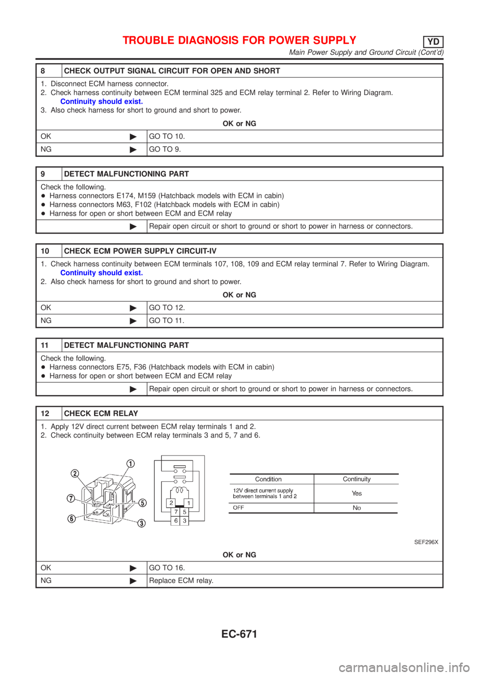
12 CHECK ECM RELAY
1. Apply 12V direct current between ECM relay terminals 1 and 2.
2. Check continuity between ECM relay terminals 3 and 5, 7 and 6.
SEF296X
OK or NG
OK©GO TO 16.
NG©Replace ECM relay.
TROUBLE DIAGNOSIS FOR POWER SUPPLYYD
Main Power Supply and Ground Circuit (Cont'd)
EC-671
Page 1396 of 2898
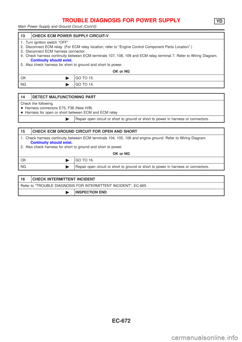
13 CHECK ECM POWER SUPPLY CIRCUIT-V
1. Turn ignition switch ªOFFº.
2. Disconnect ECM relay. (For ECM relay location, refer to ªEngine Control Component Parts Locationº.)
3. Disconnect ECM harness connector.
4. Check harness continuity between ECM terminals 107, 108, 109 and ECM relay terminal 7. Refer to Wiring Diagram.
Continuity should exist.
5. Also check harness for short to ground and short to power.
OK or NG
OK©GO TO 15.
NG©GO TO 14.
14 DETECT MALFUNCTIONING PART
Check the following.
+Harness connectors E75, F36 (New H/B)
+Harness for open or short between ECM and ECM relay
©Repair open circuit or short to ground or short to power in harness or connectors.
15 CHECK ECM GROUND CIRCUIT FOR OPEN AND SHORT
1. Check harness continuity between ECM terminals 104, 105, 106 and engine ground. Refer to Wiring Diagram.
Continuity should exist.
2. Also check harness for short to ground and short to power.
OK or NG
OK©GO TO 16.
NG©Repair open circuit or short to ground or short to power in harness or connectors.
16 CHECK INTERMITTENT INCIDENT
Refer to ªTROUBLE DIAGNOSIS FOR INTERMITTENT INCIDENTº, EC-665.
©INSPECTION END
TROUBLE DIAGNOSIS FOR POWER SUPPLYYD
Main Power Supply and Ground Circuit (Cont'd)
EC-672
Page 1397 of 2898
SEF987W
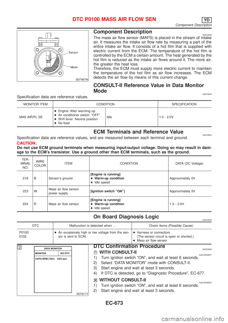
Component DescriptionNJEC0642The mass air flow sensor (MAFS) is placed in the stream of intake
air. It measures the intake air flow rate by measuring a part of the
entire intake air flow. It consists of a hot film that is supplied with
electric current from the ECM. The temperature of the hot film is
controlled by the ECM a certain amount. The heat generated by the
hot film is reduced as the intake air flows around it. The more air,
the greater the heat loss.
Therefore, the ECM must supply more electric current to maintain
the temperature of the hot film as air flow increases. The ECM
detects the air flow by means of this current change.
CONSULT-II Reference Value in Data Monitor
Mode
NJEC0643Specification data are reference values.
MONITOR ITEM CONDITION SPECIFICATION
MAS AIR/FL SE+Engine: After warming up
+Air conditioner switch: ªOFFº
+Shift lever: Neutral position
+No-loadIdle 1.5 - 2.0V
ECM Terminals and Reference ValueNJEC0644Specification data are reference values, and are measured between each terminal and ground.
CAUTION:
Do not use ECM ground terminals when measuring input/output voltage. Doing so may result in dam-
age to the ECM's transistor. Use a ground other than ECM terminals, such as the ground.
TER-
MINAL
NO.WIRE
COLORITEM CONDITION DATA (DC Voltage)
218 B Sensor's ground[Engine is running]
+Warm-up condition
+Idle speedApproximately 0V
223 WMass air flow sensor
power supply[Ignition switch ªONº]Approximately 5V
224 R Mass air flow sensor[Engine is running]
+Warm-up condition
+Idle speed1.5 - 2.0V
On Board Diagnosis LogicNJEC0645
DTC Malfunction is detected when ... Check Items (Possible Cause)
P0100
0102+An excessively high or low voltage from the sen-
sor is sent to ECM.+Harness or connectors
(The sensor circuit is open or shorted.)
+Mass air flow sensor
SEF817Y
DTC Confirmation ProcedureNJEC0646WITH CONSULT-IINJEC0646S011) Turn ignition switch ªONº, and wait at least 6 seconds.
2) Select ªDATA MONITORº mode with CONSULT-II.
3) Start engine and wait at least 3 seconds.
4) If DTC is detected, go to ªDiagnostic Procedureº, EC-677.
WITHOUT CONSULT-IINJEC0646S021) Turn ignition switch ªONº, and wait at least 6 seconds.
2) Start engine and wait at least 3 seconds.
DTC P0100 MASS AIR FLOW SENYD
Component Description
EC-673
Page 1398 of 2898

3) Turn ignition switch ªOFFº, wait at least 5 seconds and then
turn ªONº.
4) Perform ªDiagnostic Test Mode II (Self-diagnostic results)º with
ECM.
5) If DTC is detected, go to ªDiagnostic Procedureº, EC-677.
DTC P0100 MASS AIR FLOW SENYD
DTC Confirmation Procedure (Cont'd)
EC-674
Page 1399 of 2898

Wiring DiagramNJEC0647SEDAN MODELS AND HATCHBACK MODELS WITH ECM IN ENGINE COMPARTMENTNJEC0647S01
HEC883
DTC P0100 MASS AIR FLOW SENYD
Wiring Diagram
EC-675
Page 1400 of 2898
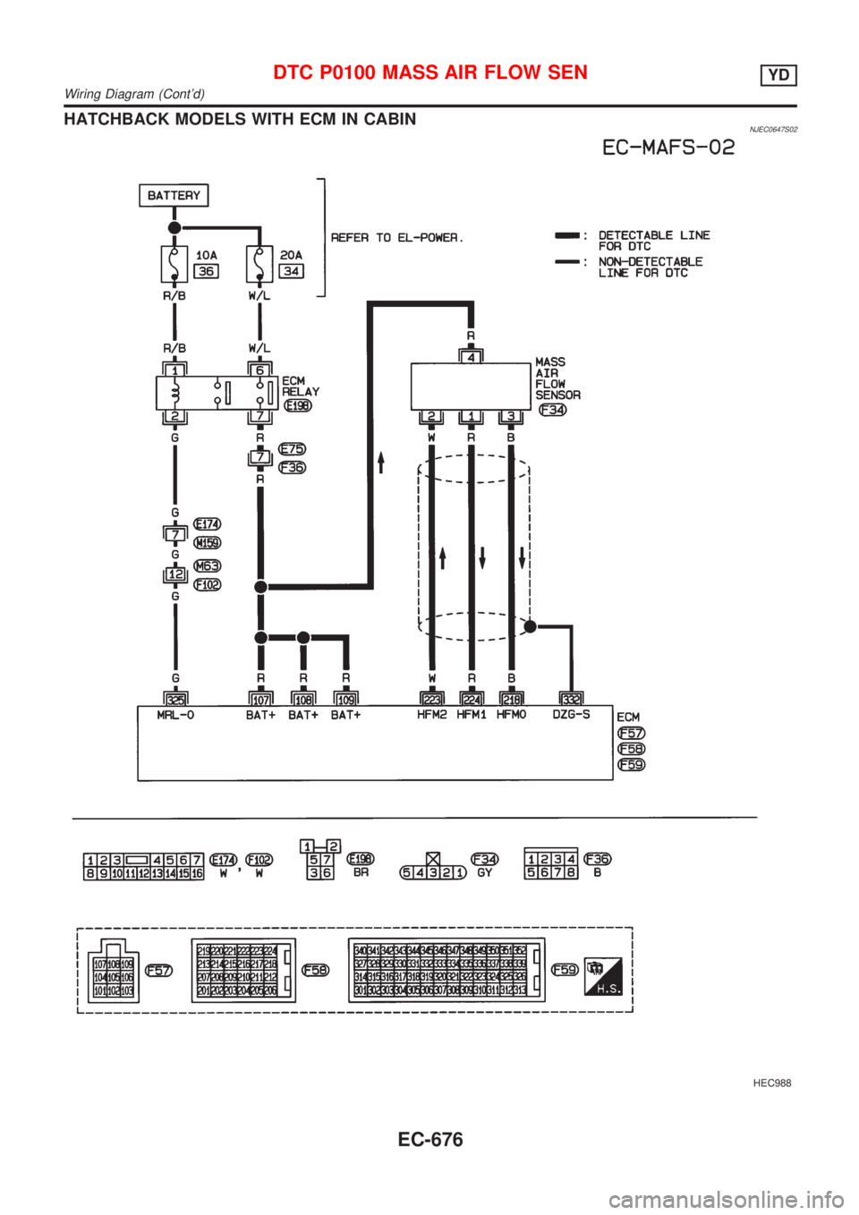
HATCHBACK MODELS WITH ECM IN CABINNJEC0647S02
HEC988
DTC P0100 MASS AIR FLOW SENYD
Wiring Diagram (Cont'd)
EC-676