air bleeding NISSAN ALMERA 2001 User Guide
[x] Cancel search | Manufacturer: NISSAN, Model Year: 2001, Model line: ALMERA, Model: NISSAN ALMERA 2001Pages: 2898, PDF Size: 60.76 MB
Page 606 of 2898
2 CHECK CONNECTOR AND PERFORMANCE
1. Disconnect ABS actuator and electric unit connector.
2. Check whether brake is effective.
OK or NG
Ye s©GO TO 3.
No©Perform Preliminary Check. Refer to BR-72.
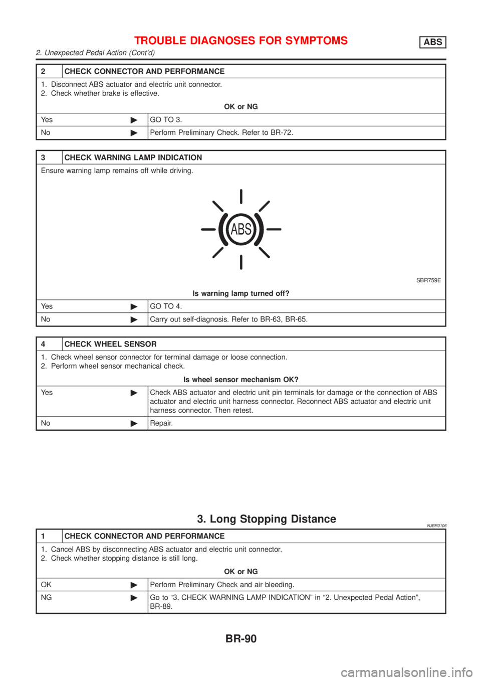
3 CHECK WARNING LAMP INDICATION
Ensure warning lamp remains off while driving.
SBR759E
Is warning lamp turned off?
Ye s©GO TO 4.
No©Carry out self-diagnosis. Refer to BR-63, BR-65.
4 CHECK WHEEL SENSOR
1. Check wheel sensor connector for terminal damage or loose connection.
2. Perform wheel sensor mechanical check.
Is wheel sensor mechanism OK?
Ye s©Check ABS actuator and electric unit pin terminals for damage or the connection of ABS
actuator and electric unit harness connector. Reconnect ABS actuator and electric unit
harness connector. Then retest.
No©Repair.
3. Long Stopping DistanceNJBR0106
1 CHECK CONNECTOR AND PERFORMANCE
1. Cancel ABS by disconnecting ABS actuator and electric unit connector.
2. Check whether stopping distance is still long.
OK or NG
OK©Perform Preliminary Check and air bleeding.
NG©Go to ª3. CHECK WARNING LAMP INDICATIONº in ª2. Unexpected Pedal Actionº,
BR-89.
TROUBLE DIAGNOSES FOR SYMPTOMSABS
2. Unexpected Pedal Action (Cont'd)
BR-90
Page 701 of 2898
CLUTCH
SECTION
CL
CONTENTS
PRECAUTIONS...............................................................2
Precautions ..................................................................2
PREPARATION...............................................................3
Special Service Tools ..................................................3
Commercial Service Tools ...........................................3
NOISE, VIBRATION AND HARSHNESS (NVH)
TROUBLESHOOTING.....................................................4
NVH Troubleshooting Chart.........................................4
CLUTCH...................................................................4
CLUTCH SYSTEM...........................................................5
Components - RHD Model with QG Engine - .............5
Components - LHD Model with QG Engine -..............6
Components - RHD Model with YD Engine -..............7
Components - LHD Model with YD Engine - ..............8
Inspection and Adjustment ..........................................9
CLUTCH PEDAL INSPECTION...................................9
CLUTCH PEDAL ADJUSTMENT...............................10
AIR BLEEDING PROCEDURE..................................10
CLUTCH MASTER CYLINDER..................................... 11
Components............................................................... 11
Removal .....................................................................12
Installation ..................................................................12
Disassembly...............................................................12
Inspection...................................................................12
Assembly ...................................................................13
OPERATING CYLINDER...............................................14
Components...............................................................14
Removal .....................................................................14
Disassembly...............................................................14
Inspection...................................................................14
Assembly ...................................................................15
Installation ..................................................................15
PIPING...........................................................................16
Removal .....................................................................16Installation ..................................................................16
RS5F30A, RS5F70A
CLUTCH RELEASE MECHANISM...............................17
Components...............................................................17
Removal .....................................................................17
Inspection...................................................................17
Installation ..................................................................17
RS5F50A
CLUTCH RELEASE MECHANISM...............................20
Components...............................................................20
Removal .....................................................................20
Inspection...................................................................20
Installation ..................................................................20
CLUTCH DISC, CLUTCH COVER AND
FLYWHEEL....................................................................22
Components...............................................................22
Inspection and Adjustment ........................................22
CLUTCH DISC.........................................................22
CLUTCH COVER.....................................................23
FLYWHEEL.............................................................23
Installation ..................................................................23
SERVICE DATA AND SPECIFICATIONS (SDS).........24
Clutch Control System ...............................................24
Clutch Master Cylinder ..............................................24
Clutch Operating Cylinder .........................................24
Clutch Disc.................................................................24
Clutch Cover ..............................................................24
Clutch Pedal ..............................................................24
Page 710 of 2898
CLUTCH PEDAL ADJUSTMENTNJCL0006S04Pedal StrokeNJCL0006S04011. Loosen the pedal stopper bolt completely (so there is no con-
tact between pedal and stopper bolt).
2. Adjust pedal stroke to the specified value with the master cyl-
inder push rod.
3. Adjust the pedal stopper bolt until it is just in contact with the
pedal, then tighten the lock nut.
4. Once stroke is set to specification, adjust clutch pedal free
play.
Pedal stroke ªSº.
Refer to ªSDSº, CL-24.
Pedal Free PlayNJCL0006S04021. Adjust pedal free play to the specified value with the master
cylinder push rod.
2. Tighten lock nut of the master cylinder push rod.
+Push on the clutch pedal until resistance is felt, and check the
distance the pedal moves.
Pedal free play ªAº.
Refer to ªSDSº, CL-24.
SCL838
SCL839
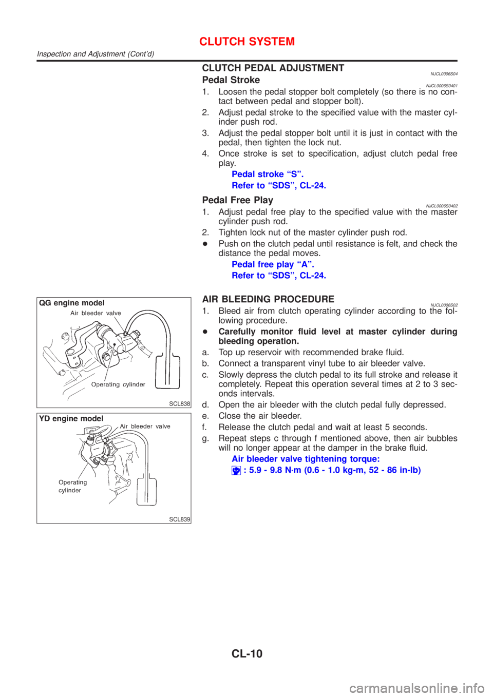
AIR BLEEDING PROCEDURENJCL0006S021. Bleed air from clutch operating cylinder according to the fol-
lowing procedure.
+Carefully monitor fluid level at master cylinder during
bleeding operation.
a. Top up reservoir with recommended brake fluid.
b. Connect a transparent vinyl tube to air bleeder valve.
c. Slowly depress the clutch pedal to its full stroke and release it
completely. Repeat this operation several times at 2 to 3 sec-
onds intervals.
d. Open the air bleeder with the clutch pedal fully depressed.
e. Close the air bleeder.
f. Release the clutch pedal and wait at least 5 seconds.
g. Repeat steps c through f mentioned above, then air bubbles
will no longer appear at the damper in the brake fluid.
Air bleeder valve tightening torque:
: 5.9 - 9.8 N´m (0.6 - 1.0 kg-m, 52 - 86 in-lb)
CLUTCH SYSTEM
Inspection and Adjustment (Cont'd)
CL-10
Page 712 of 2898
RemovalNJCL00081. Drain brake fluid.
CAUTION:
Be careful not to splash brake fluid on painted areas; it may
cause paint damage. If brake fluid is splashed on painted
areas, wash it away with water immediately.
2. Remove clutch tube using a flare nut wrench.
3. Remove snap pin between clutch pedal and push rod, and
remove clevis pin.
4. Unscrew master cylinder assembly mounting nuts and remove
master cylinder assembly from vehicle.
InstallationNJCL00091. Connect clutch tube to master cylinder assembly, and hand-
tighten flare nut.
2. Install master cylinder assembly to vehicle, and tighten mount-
ing nuts to the specified torque.
: 11 - 14 N´m (1.1 - 1.5 kg-m,8-10ft-lb)
3. Tighten clutch tube flare nut using a flare nut torque wrench.
: 15 - 18 N´m (1.5 - 1.8 kg-m, 11 - 13 ft-lb)
4. After installing clevis pin, install snap pin to connect clutch
pedal to push rod.
5. After finishing the operation, bleed air from clutch piping con-
nector and operating cylinder. (Refer to ªAir Bleeding
Procedureº, CL-10.)
SCL725
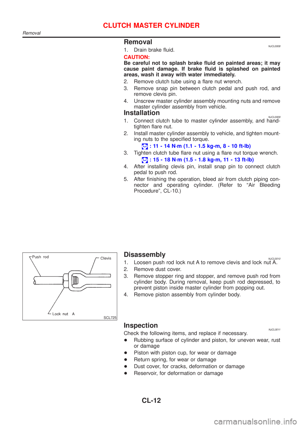
DisassemblyNJCL00101. Loosen push rod lock nut A to remove clevis and lock nut A.
2. Remove dust cover.
3. Remove stopper ring and stopper, and remove push rod from
cylinder body. During removal, keep push rod depressed, to
prevent piston inside master cylinder from popping out.
4. Remove piston assembly from cylinder body.
InspectionNJCL0011Check the following items, and replace if necessary.
+Rubbing surface of cylinder and piston, for uneven wear, rust
or damage
+Piston with piston cup, for wear or damage
+Return spring, for wear or damage
+Dust cover, for cracks, deformation or damage
+Reservoir, for deformation or damage
CLUTCH MASTER CYLINDER
Removal
CL-12
Page 715 of 2898
AssemblyNJCL00231. Apply recommended rubber grease to piston cup and piston,
and insert piston assembly.
2. Install dust cover.
InstallationNJCL0024Install the components in the reverse order of removal. Adhere to
the operations described below.
CAUTION:
Install the hose without twisting it.
+The copper washer of the union bolt should not be reused.
Always use a new copper washer for installation.
+After finishing the operation, bleed air from the clutch
piping connector and operating cylinder. Refer to ªAir
Bleeding Procedureº, CL-10.
OPERATING CYLINDER
Assembly
CL-15
Page 716 of 2898
SCL729
RemovalNJCL00421. Remove fuel filter mounting bracket.
2. Remove air cleaner and air duct.
3. Drain brake fluid.
CAUTION:
Be careful not to splash brake fluid on painted areas; it may
cause paint damage. If brake fluid is splashed on painted
areas, wash it away with water immediately.
4. Remove flare nut using a flare nut wrench.
5. Remove clutch hose and clutch tube.
SCL730
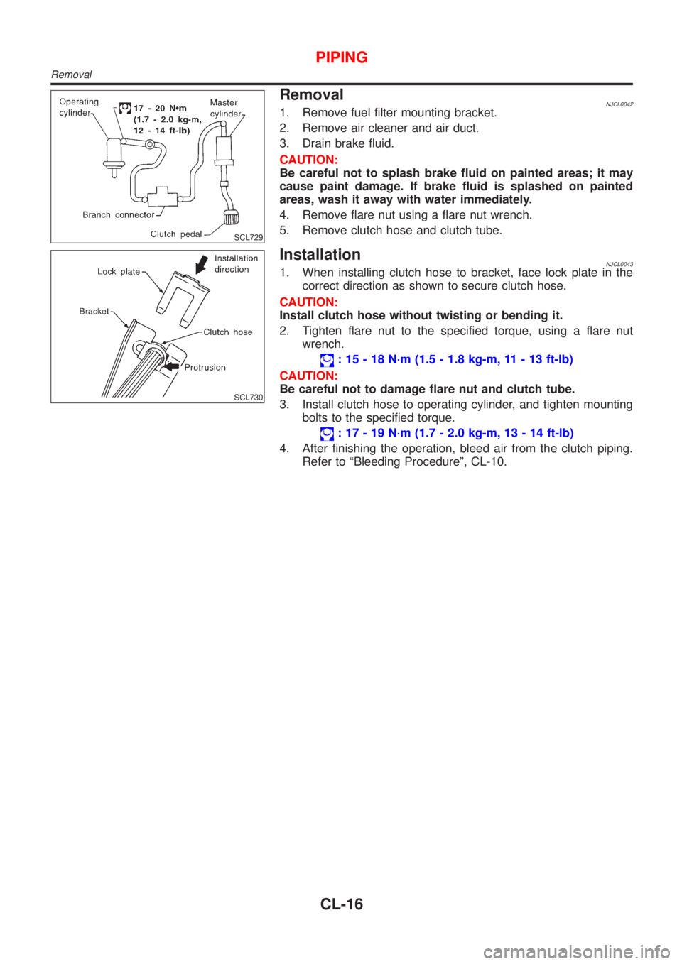
InstallationNJCL00431. When installing clutch hose to bracket, face lock plate in the
correct direction as shown to secure clutch hose.
CAUTION:
Install clutch hose without twisting or bending it.
2. Tighten flare nut to the specified torque, using a flare nut
wrench.
: 15 - 18 N´m (1.5 - 1.8 kg-m, 11 - 13 ft-lb)
CAUTION:
Be careful not to damage flare nut and clutch tube.
3. Install clutch hose to operating cylinder, and tighten mounting
bolts to the specified torque.
: 17 - 19 N´m (1.7 - 2.0 kg-m, 13 - 14 ft-lb)
4. After finishing the operation, bleed air from the clutch piping.
Refer to ªBleeding Procedureº, CL-10.
PIPING
Removal
CL-16
Page 1341 of 2898
JEF346Y
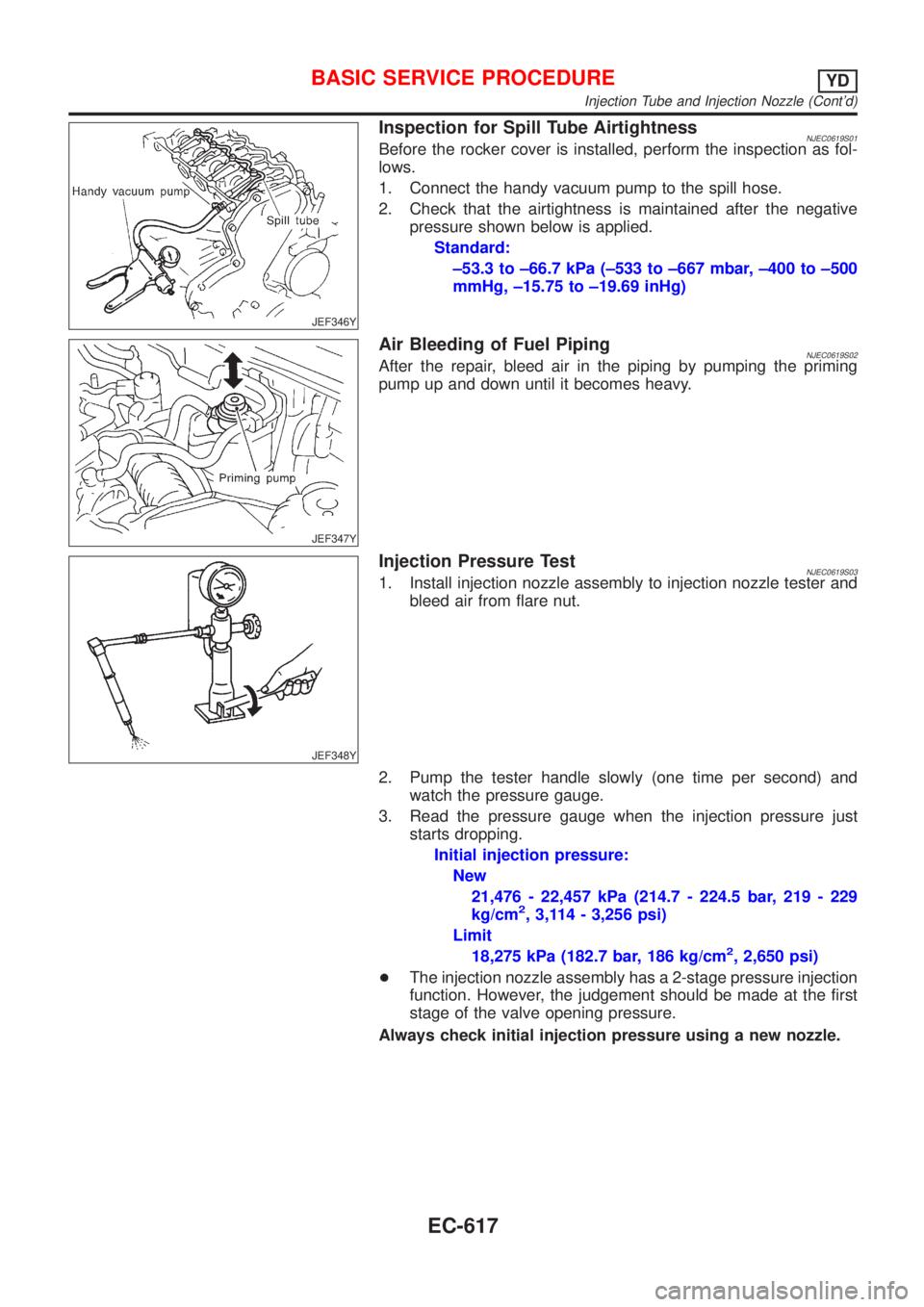
Inspection for Spill Tube AirtightnessNJEC0619S01Before the rocker cover is installed, perform the inspection as fol-
lows.
1. Connect the handy vacuum pump to the spill hose.
2. Check that the airtightness is maintained after the negative
pressure shown below is applied.
Standard:
±53.3 to ±66.7 kPa (±533 to ±667 mbar, ±400 to ±500
mmHg, ±15.75 to ±19.69 inHg)
JEF347Y
Air Bleeding of Fuel PipingNJEC0619S02After the repair, bleed air in the piping by pumping the priming
pump up and down until it becomes heavy.
JEF348Y
Injection Pressure TestNJEC0619S031. Install injection nozzle assembly to injection nozzle tester and
bleed air from flare nut.
2. Pump the tester handle slowly (one time per second) and
watch the pressure gauge.
3. Read the pressure gauge when the injection pressure just
starts dropping.
Initial injection pressure:
New
21,476 - 22,457 kPa (214.7 - 224.5 bar, 219 - 229
kg/cm
2, 3,114 - 3,256 psi)
Limit
18,275 kPa (182.7 bar, 186 kg/cm
2, 2,650 psi)
+The injection nozzle assembly has a 2-stage pressure injection
function. However, the judgement should be made at the first
stage of the valve opening pressure.
Always check initial injection pressure using a new nozzle.
BASIC SERVICE PROCEDUREYD
Injection Tube and Injection Nozzle (Cont'd)
EC-617
Page 1349 of 2898
Fuel Filter
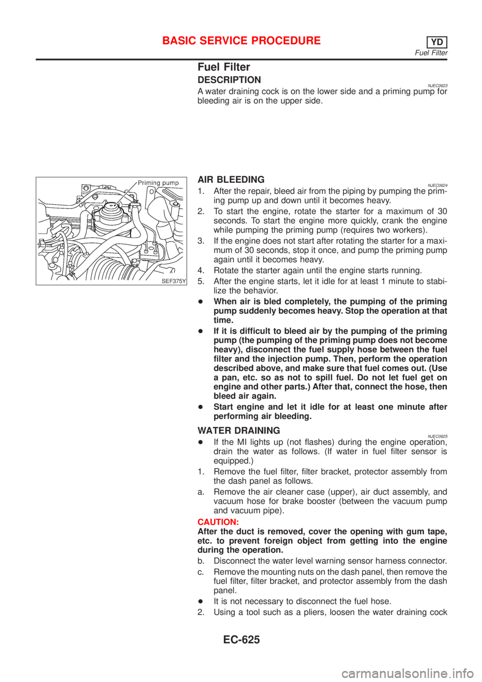
DESCRIPTIONNJEC0623A water draining cock is on the lower side and a priming pump for
bleeding air is on the upper side.
SEF375Y
AIR BLEEDINGNJEC06241. After the repair, bleed air from the piping by pumping the prim-
ing pump up and down until it becomes heavy.
2. To start the engine, rotate the starter for a maximum of 30
seconds. To start the engine more quickly, crank the engine
while pumping the priming pump (requires two workers).
3. If the engine does not start after rotating the starter for a maxi-
mum of 30 seconds, stop it once, and pump the priming pump
again until it becomes heavy.
4. Rotate the starter again until the engine starts running.
5. After the engine starts, let it idle for at least 1 minute to stabi-
lize the behavior.
+When air is bled completely, the pumping of the priming
pump suddenly becomes heavy. Stop the operation at that
time.
+If it is difficult to bleed air by the pumping of the priming
pump (the pumping of the priming pump does not become
heavy), disconnect the fuel supply hose between the fuel
filter and the injection pump. Then, perform the operation
described above, and make sure that fuel comes out. (Use
a pan, etc. so as not to spill fuel. Do not let fuel get on
engine and other parts.) After that, connect the hose, then
bleed air again.
+Start engine and let it idle for at least one minute after
performing air bleeding.
WATER DRAININGNJEC0625+If the MI lights up (not flashes) during the engine operation,
drain the water as follows. (If water in fuel filter sensor is
equipped.)
1. Remove the fuel filter, filter bracket, protector assembly from
the dash panel as follows.
a. Remove the air cleaner case (upper), air duct assembly, and
vacuum hose for brake booster (between the vacuum pump
and vacuum pipe).
CAUTION:
After the duct is removed, cover the opening with gum tape,
etc. to prevent foreign object from getting into the engine
during the operation.
b. Disconnect the water level warning sensor harness connector.
c. Remove the mounting nuts on the dash panel, then remove the
fuel filter, filter bracket, and protector assembly from the dash
panel.
+It is not necessary to disconnect the fuel hose.
2. Using a tool such as a pliers, loosen the water draining cock
BASIC SERVICE PROCEDUREYD
Fuel Filter
EC-625
Page 1350 of 2898
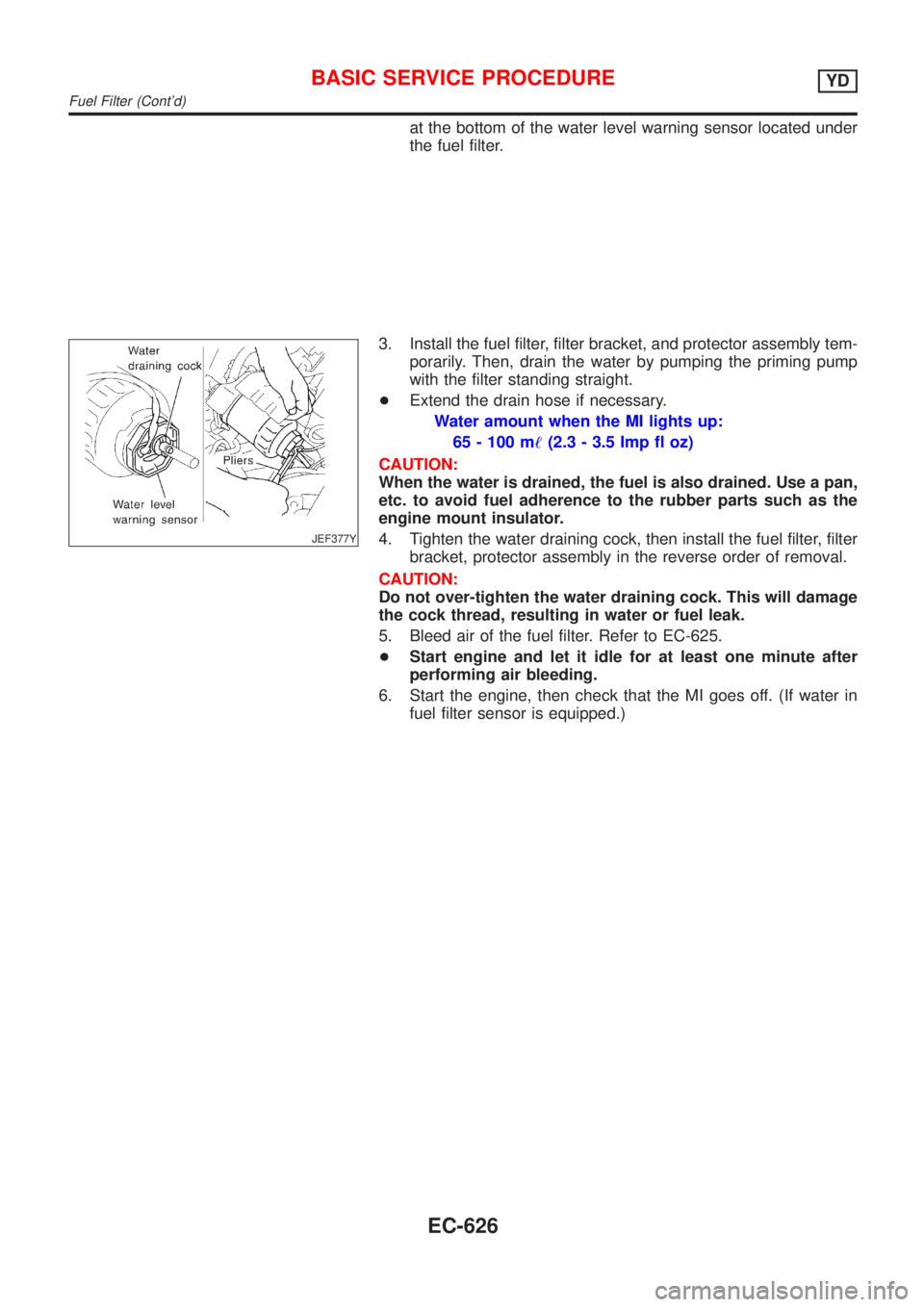
at the bottom of the water level warning sensor located under
the fuel filter.
JEF377Y
3. Install the fuel filter, filter bracket, and protector assembly tem-
porarily. Then, drain the water by pumping the priming pump
with the filter standing straight.
+Extend the drain hose if necessary.
Water amount when the MI lights up:
65 - 100 m!(2.3 - 3.5 Imp fl oz)
CAUTION:
When the water is drained, the fuel is also drained. Use a pan,
etc. to avoid fuel adherence to the rubber parts such as the
engine mount insulator.
4. Tighten the water draining cock, then install the fuel filter, filter
bracket, protector assembly in the reverse order of removal.
CAUTION:
Do not over-tighten the water draining cock. This will damage
the cock thread, resulting in water or fuel leak.
5. Bleed air of the fuel filter. Refer to EC-625.
+Start engine and let it idle for at least one minute after
performing air bleeding.
6. Start the engine, then check that the MI goes off. (If water in
fuel filter sensor is equipped.)
BASIC SERVICE PROCEDUREYD
Fuel Filter (Cont'd)
EC-626
Page 1366 of 2898
3 CHECK IDLE SPEED
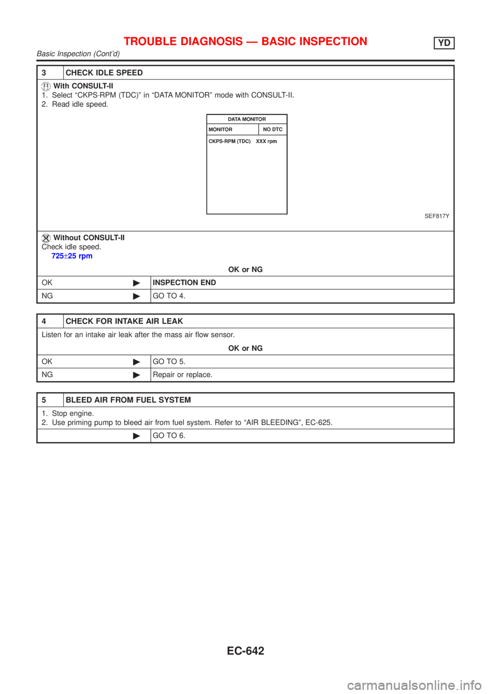
With CONSULT-II
1. Select ªCKPS´RPM (TDC)º in ªDATA MONITORº mode with CONSULT-II.
2. Read idle speed.
SEF817Y
Without CONSULT-II
Check idle speed.
725±25 rpm
OK or NG
OK©INSPECTION END
NG©GO TO 4.
4 CHECK FOR INTAKE AIR LEAK
Listen for an intake air leak after the mass air flow sensor.
OK or NG
OK©GO TO 5.
NG©Repair or replace.
5 BLEED AIR FROM FUEL SYSTEM
1. Stop engine.
2. Use priming pump to bleed air from fuel system. Refer to ªAIR BLEEDINGº, EC-625.
©GO TO 6.
TROUBLE DIAGNOSIS Ð BASIC INSPECTIONYD
Basic Inspection (Cont'd)
EC-642