NISSAN ALMERA 2001 Service Manual
Manufacturer: NISSAN, Model Year: 2001, Model line: ALMERA, Model: NISSAN ALMERA 2001Pages: 2898, PDF Size: 60.76 MB
Page 2131 of 2898
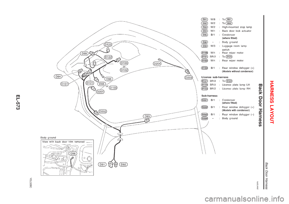
Back Door HarnessNJEL0492
YEL328C
HARNESS LAYOUT
Back Door Harness
EL-573
Page 2132 of 2898
NJEL0144
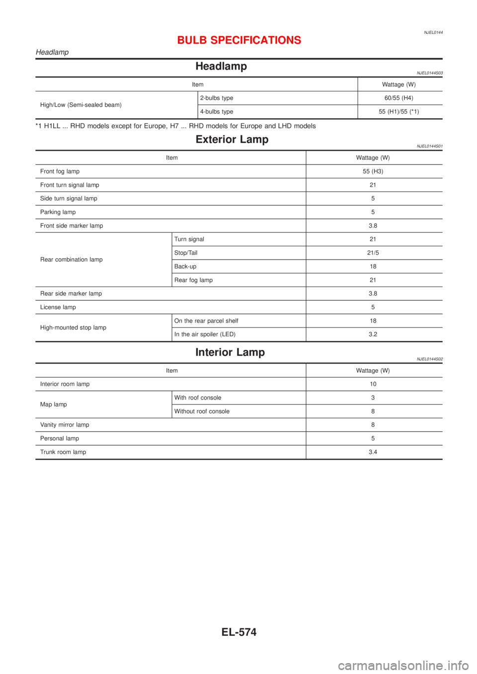
HeadlampNJEL0144S03
Item Wattage (W)
High/Low (Semi-sealed beam)2-bulbs type 60/55 (H4)
4-bulbs type 55 (H1)/55 (*1)
*1 H1LL ... RHD models except for Europe, H7 ... RHD models for Europe and LHD models
Exterior LampNJEL0144S01
Item Wattage (W)
Front fog lamp55 (H3)
Front turn signal lamp21
Side turn signal lamp5
Parking lamp5
Front side marker lamp3.8
Rear combination lampTurn signal 21
Stop/Tail 21/5
Back-up 18
Rear fog lamp 21
Rear side marker lamp3.8
License lamp5
High-mounted stop lampOn the rear parcel shelf 18
In the air spoiler (LED) 3.2
Interior LampNJEL0144S02
Item Wattage (W)
Interior room lamp10
Map lampWith roof console 3
Without roof console 8
Vanity mirror lamp8
Personal lamp5
Trunk room lamp3.4
BULB SPECIFICATIONS
Headlamp
EL-574
Page 2133 of 2898
NJEL0311
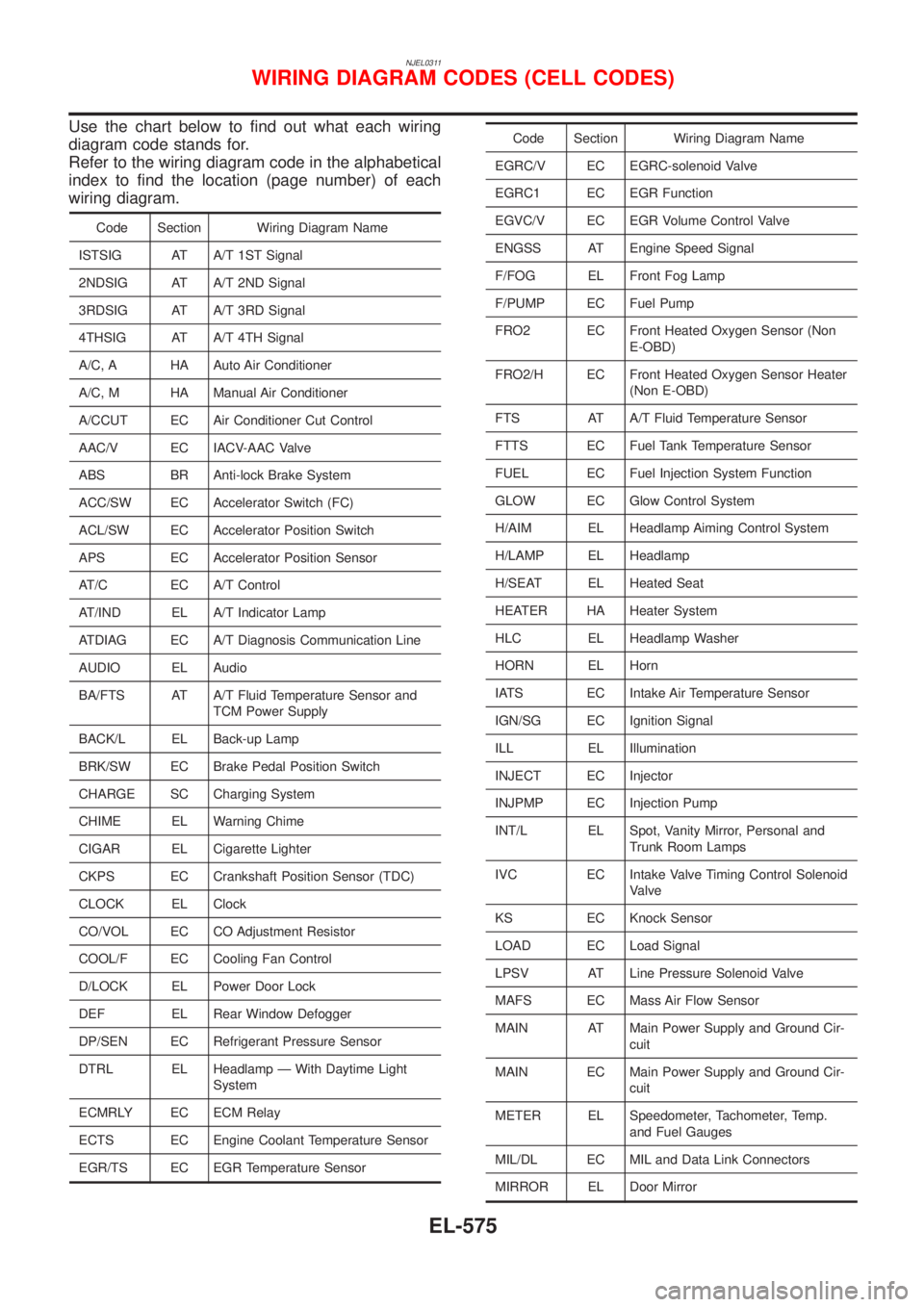
Use the chart below to find out what each wiring
diagram code stands for.
Refer to the wiring diagram code in the alphabetical
index to find the location (page number) of each
wiring diagram.
Code Section Wiring Diagram Name
ISTSIG AT A/T 1ST Signal
2NDSIG AT A/T 2ND Signal
3RDSIG AT A/T 3RD Signal
4THSIG AT A/T 4TH Signal
A/C, A HA Auto Air Conditioner
A/C, M HA Manual Air Conditioner
A/CCUT EC Air Conditioner Cut Control
AAC/V EC IACV-AAC Valve
ABS BR Anti-lock Brake System
ACC/SW EC Accelerator Switch (FC)
ACL/SW EC Accelerator Position Switch
APS EC Accelerator Position Sensor
AT/C EC A/T Control
AT/IND EL A/T Indicator Lamp
ATDIAG EC A/T Diagnosis Communication Line
AUDIO EL Audio
BA/FTS AT A/T Fluid Temperature Sensor and
TCM Power Supply
BACK/L EL Back-up Lamp
BRK/SW EC Brake Pedal Position Switch
CHARGE SC Charging System
CHIME EL Warning Chime
CIGAR EL Cigarette Lighter
CKPS EC Crankshaft Position Sensor (TDC)
CLOCK EL Clock
CO/VOL EC CO Adjustment Resistor
COOL/F EC Cooling Fan Control
D/LOCK EL Power Door Lock
DEF EL Rear Window Defogger
DP/SEN EC Refrigerant Pressure Sensor
DTRL EL Headlamp Ð With Daytime Light
System
ECMRLY EC ECM Relay
ECTS EC Engine Coolant Temperature Sensor
EGR/TS EC EGR Temperature Sensor
Code Section Wiring Diagram Name
EGRC/V EC EGRC-solenoid Valve
EGRC1 EC EGR Function
EGVC/V EC EGR Volume Control Valve
ENGSS AT Engine Speed Signal
F/FOG EL Front Fog Lamp
F/PUMP EC Fuel Pump
FRO2 EC Front Heated Oxygen Sensor (Non
E-OBD)
FRO2/H EC Front Heated Oxygen Sensor Heater
(Non E-OBD)
FTS AT A/T Fluid Temperature Sensor
FTTS EC Fuel Tank Temperature Sensor
FUEL EC Fuel Injection System Function
GLOW EC Glow Control System
H/AIM EL Headlamp Aiming Control System
H/LAMP EL Headlamp
H/SEAT EL Heated Seat
HEATER HA Heater System
HLC EL Headlamp Washer
HORN EL Horn
IATS EC Intake Air Temperature Sensor
IGN/SG EC Ignition Signal
ILL EL Illumination
INJECT EC Injector
INJPMP EC Injection Pump
INT/L EL Spot, Vanity Mirror, Personal and
Trunk Room Lamps
IVC EC Intake Valve Timing Control Solenoid
Valve
KS EC Knock Sensor
LOAD EC Load Signal
LPSV AT Line Pressure Solenoid Valve
MAFS EC Mass Air Flow Sensor
MAIN AT Main Power Supply and Ground Cir-
cuit
MAIN EC Main Power Supply and Ground Cir-
cuit
METER EL Speedometer, Tachometer, Temp.
and Fuel Gauges
MIL/DL EC MIL and Data Link Connectors
MIRROR EL Door Mirror
WIRING DIAGRAM CODES (CELL CODES)
EL-575
Page 2134 of 2898
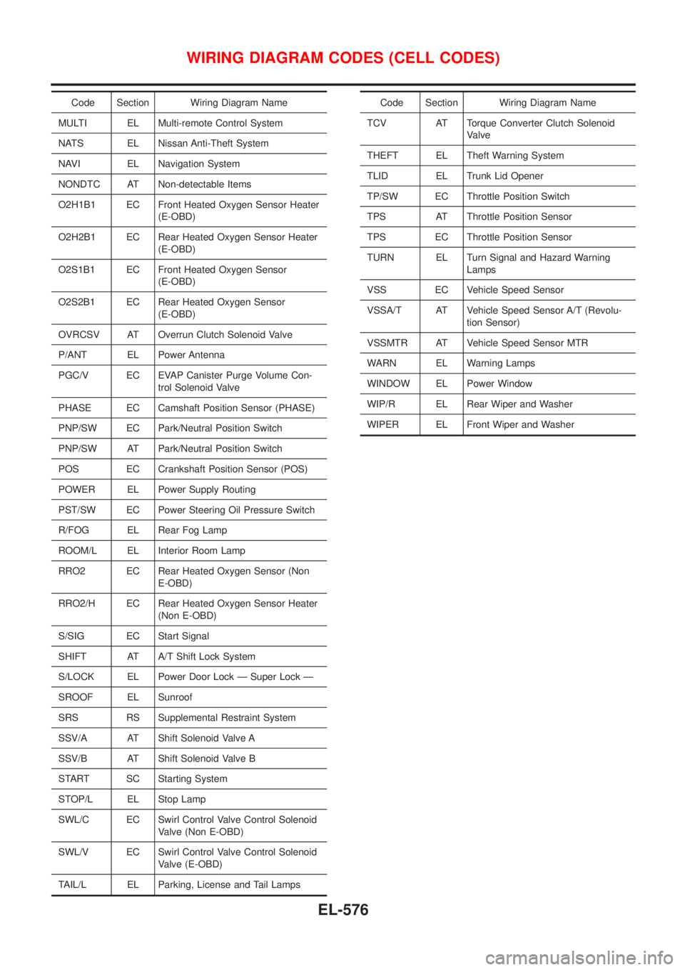
Code Section Wiring Diagram Name
MULTI EL Multi-remote Control System
NATS EL Nissan Anti-Theft System
NAVI EL Navigation System
NONDTC AT Non-detectable Items
O2H1B1 EC Front Heated Oxygen Sensor Heater
(E-OBD)
O2H2B1 EC Rear Heated Oxygen Sensor Heater
(E-OBD)
O2S1B1 EC Front Heated Oxygen Sensor
(E-OBD)
O2S2B1 EC Rear Heated Oxygen Sensor
(E-OBD)
OVRCSV AT Overrun Clutch Solenoid Valve
P/ANT EL Power Antenna
PGC/V EC EVAP Canister Purge Volume Con-
trol Solenoid Valve
PHASE EC Camshaft Position Sensor (PHASE)
PNP/SW EC Park/Neutral Position Switch
PNP/SW AT Park/Neutral Position Switch
POS EC Crankshaft Position Sensor (POS)
POWER EL Power Supply Routing
PST/SW EC Power Steering Oil Pressure Switch
R/FOG EL Rear Fog Lamp
ROOM/L EL Interior Room Lamp
RRO2 EC Rear Heated Oxygen Sensor (Non
E-OBD)
RRO2/H EC Rear Heated Oxygen Sensor Heater
(Non E-OBD)
S/SIG EC Start Signal
SHIFT AT A/T Shift Lock System
S/LOCK EL Power Door Lock Ð Super Lock Ð
SROOF EL Sunroof
SRS RS Supplemental Restraint System
SSV/A AT Shift Solenoid Valve A
SSV/B AT Shift Solenoid Valve B
START SC Starting System
STOP/L EL Stop Lamp
SWL/C EC Swirl Control Valve Control Solenoid
Valve (Non E-OBD)
SWL/V EC Swirl Control Valve Control Solenoid
Valve (E-OBD)
TAIL/L EL Parking, License and Tail LampsCode Section Wiring Diagram Name
TCV AT Torque Converter Clutch Solenoid
Valve
THEFT EL Theft Warning System
TLID EL Trunk Lid Opener
TP/SW EC Throttle Position Switch
TPS AT Throttle Position Sensor
TPS EC Throttle Position Sensor
TURN EL Turn Signal and Hazard Warning
Lamps
VSS EC Vehicle Speed Sensor
VSSA/T AT Vehicle Speed Sensor A/T (Revolu-
tion Sensor)
VSSMTR AT Vehicle Speed Sensor MTR
WARN EL Warning Lamps
WINDOW EL Power Window
WIP/R EL Rear Wiper and Washer
WIPER EL Front Wiper and Washer
WIRING DIAGRAM CODES (CELL CODES)
EL-576
Page 2135 of 2898
ENGINE MECHANICAL
SECTION
EM
CONTENTS
QG
PRECAUTIONS...............................................................4
Parts Requiring Angular Tightening .............................4
Liquid Gasket Application Procedure ..........................4
PREPARATION...............................................................5
Special Service Tools ..................................................5
Commercial Service Tools ...........................................7
NOISE, VIBRATION AND HARSHNESS (NVH)
TROUBLESHOOTING.....................................................9
NVH Troubleshooting - Engine Noise .........................9
OUTER COMPONENT PARTS..................................... 11
Removal and Installation ........................................... 11
MEASUREMENT OF COMPRESSION PRESSURE....15
DRIVE BELTS................................................................16
Checking ....................................................................16
AIR CLEANER...............................................................18
Cleaning and Changing .............................................18
VISCOUS PAPER TYPE...........................................18
DRY PAPER TYPE..................................................18
SPARK PLUG................................................................19
Checking and Changing ............................................19
OIL PAN.........................................................................20
Components...............................................................20
Removal .....................................................................20
Installation ..................................................................21
TIMING CHAIN..............................................................23
Components...............................................................23
Removal .....................................................................24
Inspection...................................................................27
Installation ..................................................................28
OIL SEAL.......................................................................32
Replacement ..............................................................32
VALVE OIL SEAL.....................................................32
FRONT OIL SEAL....................................................32
REAR OIL SEAL......................................................33
CYLINDER HEAD..........................................................34
Components...............................................................34
Removal .....................................................................35
Disassembly...............................................................37Inspection...................................................................37
CYLINDER HEAD DISTORTION...............................37
CAMSHAFT VISUAL CHECK....................................37
CAMSHAFT RUNOUT..............................................38
CAMSHAFT CAM HEIGHT.......................................38
CAMSHAFT JOURNAL CLEARANCE........................38
CAMSHAFT END PLAY............................................39
CAMSHAFT SPROCKET RUNOUT...........................39
VALVE GUIDE CLEARANCE....................................39
VALVE GUIDE REPLACEMENT................................40
VALVE SEATS.........................................................41
REPLACING VALVE SEAT FOR SERVICE PARTS....41
VALVE DIMENSIONS...............................................42
VALVE SPRING.......................................................42
VALVE LIFTER AND VALVE SHIM............................43
Valve Clearance.........................................................44
CHECKING.............................................................44
ADJUSTING............................................................45
Assembly ...................................................................46
Installation ..................................................................47
ENGINE ASSEMBLY.....................................................51
Removal and Installation ...........................................51
REMOVAL...............................................................52
INSTALLATION........................................................53
CYLINDER BLOCK.......................................................54
Components...............................................................54
Removal and Installation ...........................................55
Disassembly...............................................................55
PISTON AND CRANKSHAFT....................................55
Inspection...................................................................56
PISTON AND PISTON PIN CLEARANCE..................56
PISTON RING SIDE CLEARANCE............................56
PISTON RING END GAP..........................................56
CONNECTING ROD BEND AND TORSION...............57
CYLINDER BLOCK DISTORTION AND WEAR...........57
PISTON-TO-BORE CLEARANCE..............................58
CRANKSHAFT.........................................................59
BEARING CLEARANCE...........................................59
CONNECTING ROD BUSHING CLEARANCE
(SMALL END)
..........................................................61
Page 2136 of 2898
REPLACEMENT OF CONNECTING ROD
BUSHING (SMALL END)
..........................................62
FLYWHEEL/DRIVE PLATE RUNOUT........................62
Assembly ...................................................................62
PISTON..................................................................62
CRANKSHAFT.........................................................63
SERVICE DATA AND SPECIFICATIONS (SDS).........66
General Specifications ...............................................66
Compression Pressure ..............................................66
Belt Deflection............................................................67
Spark Plug .................................................................67
Cylinder Head ............................................................67
Valve ..........................................................................68
VALVE....................................................................68
VALVE SPRING.......................................................68
VALVE LIFTER........................................................68
VALVE CLEARANCE................................................69
VALVE GUIDE.........................................................69
AVAILABLE SHIMS..................................................69
VALVE SEAT...........................................................71
VALVE SEAT RESURFACE LIMIT.............................72
Camshaft and Camshaft Bearing ..............................72
Cylinder Block ............................................................73
Piston, Piston Ring and Piston Pin ...........................74
PISTON..................................................................74
PISTON RING.........................................................74
PISTON PIN............................................................74
Connecting Rod .........................................................75
Crankshaft..................................................................75
Main Bearing..............................................................75
STANDARD.............................................................75
UNDERSIZE............................................................75
Connecting Rod Bearing ...........................................76
STANDARD SIZE....................................................76
UNDERSIZE............................................................76
Bearing Clearance .....................................................76
Miscellaneous Components.......................................76
YD
PRECAUTIONS.............................................................77
Parts Requiring Angular Tightening ...........................77
Liquid Gasket Application Procedure ........................77
PREPARATION.............................................................78
Special Service Tools ................................................78
Commercial Service Tools .........................................80
NOISE, VIBRATION AND HARSHNESS (NVH)
TROUBLESHOOTING...................................................82
NVH Troubleshooting - Engine Noise .......................82
MEASUREMENT OF COMPRESSION PRESSURE....83
DRIVE BELTS................................................................85
Inspection...................................................................85
Adjustment .................................................................85
AIR CONDITIONER COMPRESSOR BELT................86
ALTERNATOR & WATER PUMP BELT.....................86
Removal .....................................................................86
Installation ..................................................................87
AIR CLEANER...............................................................88
Changing Air Cleaner Filter .......................................88
VISCOUS PAPER TYPE...........................................88
OIL PAN.........................................................................89
Components...............................................................89
Removal .....................................................................89
Installation ..................................................................91
TIMING CHAIN..............................................................94
Secondary Timing Chain ...........................................94
REMOVAL...............................................................94
INSPECTION...........................................................96
INSTALLATION........................................................96
Primary Timing Chain ................................................99
REMOVAL.............................................................100
INSPECTION.........................................................102
INSTALLATION......................................................102
INTAKE MANIFOLD....................................................107
Removal and Installation .........................................107
PREPARATIVE WORK...........................................107
FUEL PIPING........................................................108
INTAKE MANIFOLD...............................................108
EGR VOLUME CONTROL VALVE...........................108
WATER HOSE.......................................................108
Inspection.................................................................109
INTAKE MANIFOLD...............................................109
CATALYST.................................................................. 110
Removal and Installation ......................................... 110
PREPARATIVE WORK........................................... 110
CATALYST............................................................ 110
GUSSET............................................................... 111
EXHAUST MANIFOLD, TURBOCHARGER............... 112
Removal and Installation ......................................... 112
PREPARATIVE WORK........................................... 112
EXHAUST MANIFOLD AND TURBOCHARGER....... 112
EXHAUST MANIFOLD GASKET............................. 113
Disassembly and Assembly ..................................... 113
TURBOCHARGER................................................. 113
Inspection................................................................. 114
EXHAUST MANIFOLD........................................... 114
TURBOCHARGER................................................. 114
ROCKER COVER........................................................ 117
Removal and Installation ......................................... 117
PREPARATIVE WORK........................................... 117
ROCKER COVER.................................................. 117
CYLINDER HEAD........................................................ 119
Components............................................................. 119
Removal ...................................................................120
PREPARATIVE WORK...........................................120
CAMSHAFT...........................................................120
CYLINDER HEAD..................................................121
Disassembly.............................................................121
Inspection.................................................................122
CONTENTS(Cont'd)
EM-2
Page 2137 of 2898
CYLINDER HEAD DISTORTION.............................122
CAMSHAFT VISUAL CHECK..................................123
CAMSHAFT RUNOUT............................................123
CAMSHAFT CAM HEIGHT.....................................123
CAMSHAFT JOURNAL CLEARANCE......................123
CAMSHAFT END PLAY..........................................124
CAMSHAFT SPROCKET RUNOUT.........................124
VALVE GUIDE CLEARANCE..................................124
VALVE GUIDE REPLACEMENT..............................125
VALVE SEATS.......................................................126
REPLACING VALVE SEAT FOR SERVICE PARTS..126
VALVE DIMENSIONS.............................................128
VALVE SPRING.....................................................128
VALVE LIFTER......................................................128
Assembly .................................................................129
Installation ................................................................129
CYLINDER HEAD GASKET SELECTION.................130
CYLINDER HEAD BOLT DEFORMATION CHECK...131
CYLINDER HEAD-TO-BLOCK DIFFERENCE
CHECK
.................................................................131
LIQUID GASKET APPLICATION ON REAR CHAIN
CASE
....................................................................131
CYLINDER HEAD INSTALLATION..........................132
GLOW PLUG INSTALLATION.................................132
CAMSHAFT INSTALLATION...................................132
Valve Clearance.......................................................133
CHECKING...........................................................133
ADJUSTING..........................................................134
ENGINE ASSEMBLY...................................................137
Removal and Installation .........................................137
REMOVAL.............................................................138
INSTALLATION......................................................139
CYLINDER BLOCK.....................................................140
Components.............................................................140
Removal and Installation .........................................141
Disassembly.............................................................141
PISTON AND CRANKSHAFT..................................141
Inspection.................................................................144
CRANKSHAFT END PLAY.....................................144
CONNECTING ROD SIDE CLEARANCE.................144
PISTON AND PISTON PIN CLEARANCE................145
PISTON RING SIDE CLEARANCE..........................145
PISTON RING END GAP........................................145
CONNECTING ROD BEND AND TORSION.............146
CYLINDER BLOCK DISTORTION AND WEAR.........146
PISTON-TO-BORE CLEARANCE............................147
CRANKSHAFT.......................................................148
MAIN BEARING HOUSING INNER DIAMETER........149
BEARING CLEARANCE.........................................149
MAIN BEARING CRUSH HEIGHT...........................153
MAIN BEARING CAP BOLT DEFORMATION...........153
CONNECTING ROD BUSHING CLEARANCE
(SMALL END)
........................................................153
CONNECTING ROD BOLT DEFORMATION............154
FLYWHEEL RUNOUT............................................154
OIL JET................................................................154
OIL JET RELIEF VALVE.........................................154
Assembly .................................................................155
PISTON................................................................155
CRANKSHAFT.......................................................155
REPLACEMENT OF PILOT BUSHING.....................158
SERVICE DATA AND SPECIFICATIONS (SDS).......160
General Specifications .............................................160
Compression Pressure ............................................160
Belt Deflection..........................................................160
Cylinder Head ..........................................................160
Valve ........................................................................161
VALVE..................................................................161
VALVE CLEARANCE..............................................161
AVAILABLE SHIMS................................................161
VALVE SPRING.....................................................162
VALVE LIFTER......................................................162
VALVE GUIDE.......................................................163
Valve Seat................................................................164
Camshaft and Camshaft Bearing ............................166
Cylinder Block ..........................................................167
Piston, Piston Ring and Piston Pin .........................167
AVAILABLE PISTON..............................................167
PISTON RING.......................................................168
PISTON PIN..........................................................168
Connecting Rod .......................................................168
Crankshaft................................................................168
Available Main Bearing ............................................169
UNDERSIZE..........................................................169
Available Connecting Rod Bearing..........................169
CONNECTING ROD BEARING...............................169
UNDERSIZE..........................................................170
Miscellaneous Components.....................................170
BEARING CLEARANCE.........................................170
CONTENTS(Cont'd)
EM-3
Page 2138 of 2898
Parts Requiring Angular TighteningNJEM0001+Use an angle wrench for the final tightening of the following
engine parts:
a) Cylinder head bolts
b) Main bearing cap bolts
c) Connecting rod cap nuts
+Do not use a torque value for final tightening.
+The torque value for these parts are for a preliminary step.
+Ensure thread and seat surfaces are clean and coated with
engine oil.
SEM164F
AEM080
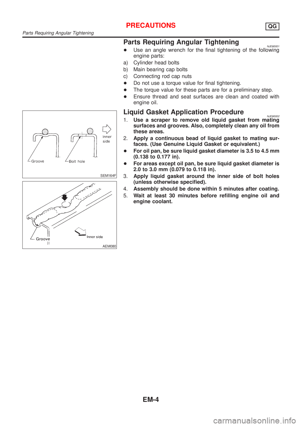
Liquid Gasket Application ProcedureNJEM00021.Use a scraper to remove old liquid gasket from mating
surfaces and grooves. Also, completely clean any oil from
these areas.
2.Apply a continuous bead of liquid gasket to mating sur-
faces. (Use Genuine Liquid Gasket or equivalent.)
+For oil pan, be sure liquid gasket diameter is 3.5 to 4.5 mm
(0.138 to 0.177 in).
+For areas except oil pan, be sure liquid gasket diameter is
2.0 to 3.0 mm (0.079 to 0.118 in).
3.Apply liquid gasket around the inner side of bolt holes
(unless otherwise specified).
4.Assembly should be done within 5 minutes after coating.
5.Wait at least 30 minutes before refilling engine oil and
engine coolant.
PRECAUTIONSQG
Parts Requiring Angular Tightening
EM-4
Page 2139 of 2898
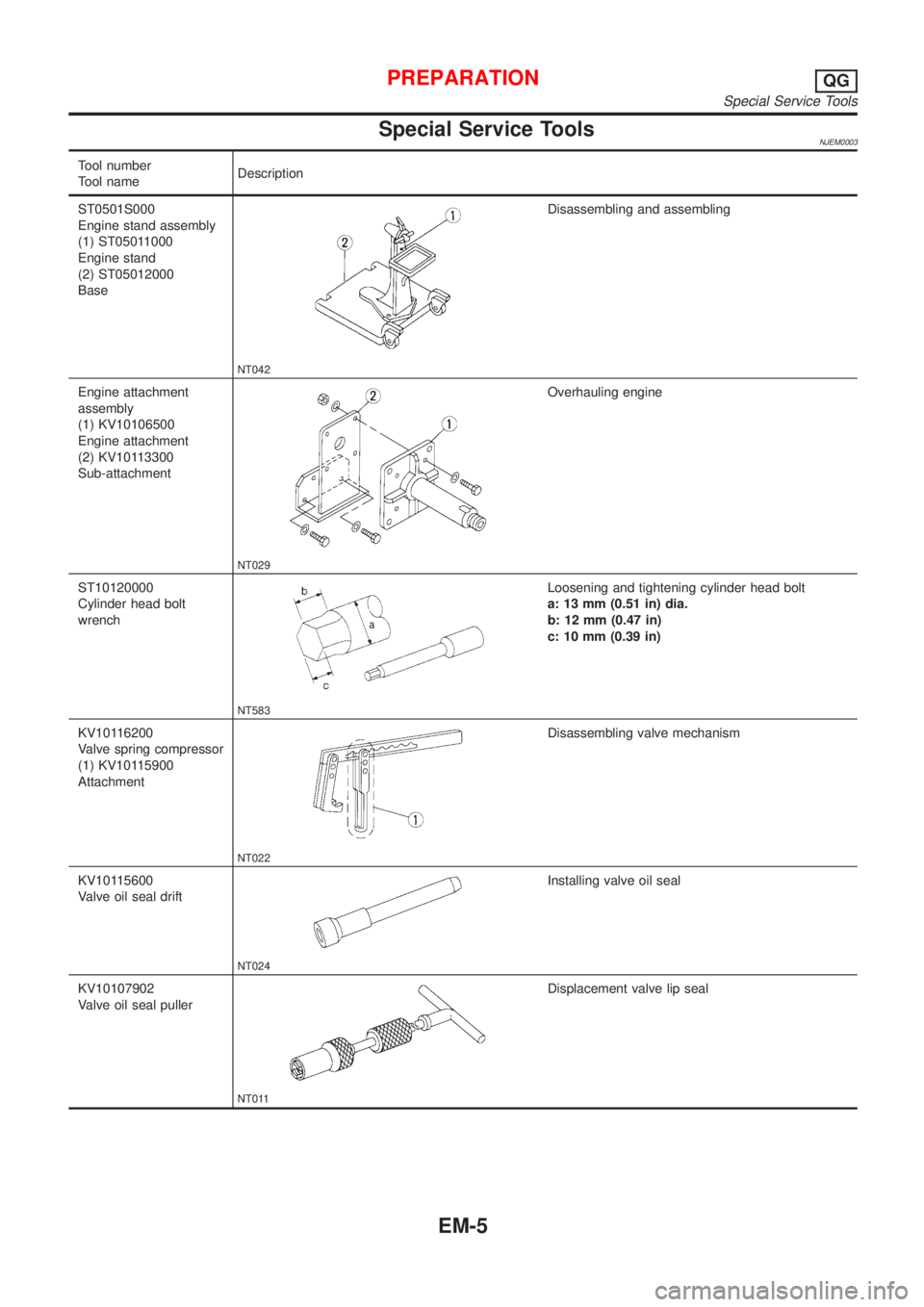
Special Service ToolsNJEM0003
Tool number
Tool nameDescription
ST0501S000
Engine stand assembly
(1) ST05011000
Engine stand
(2) ST05012000
Base
NT042
Disassembling and assembling
Engine attachment
assembly
(1) KV10106500
Engine attachment
(2) KV10113300
Sub-attachment
NT029
Overhauling engine
ST10120000
Cylinder head bolt
wrench
NT583
Loosening and tightening cylinder head bolt
a: 13 mm (0.51 in) dia.
b: 12 mm (0.47 in)
c: 10 mm (0.39 in)
KV10116200
Valve spring compressor
(1) KV10115900
Attachment
NT022
Disassembling valve mechanism
KV10115600
Valve oil seal drift
NT024
Installing valve oil seal
KV10107902
Valve oil seal puller
NT011
Displacement valve lip seal
PREPARATIONQG
Special Service Tools
EM-5
Page 2140 of 2898
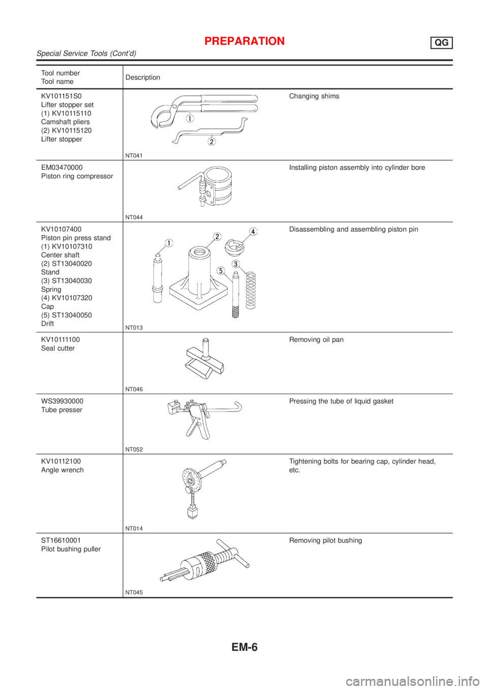
Tool number
Tool nameDescription
KV101151S0
Lifter stopper set
(1) KV10115110
Camshaft pliers
(2) KV10115120
Lifter stopper
NT041
Changing shims
EM03470000
Piston ring compressor
NT044
Installing piston assembly into cylinder bore
KV10107400
Piston pin press stand
(1) KV10107310
Center shaft
(2) ST13040020
Stand
(3) ST13040030
Spring
(4) KV10107320
Cap
(5) ST13040050
Drift
NT013
Disassembling and assembling piston pin
KV101111 0 0
Seal cutter
NT046
Removing oil pan
WS39930000
Tube presser
NT052
Pressing the tube of liquid gasket
KV10112100
Angle wrench
NT014
Tightening bolts for bearing cap, cylinder head,
etc.
ST16610001
Pilot bushing puller
NT045
Removing pilot bushing
PREPARATIONQG
Special Service Tools (Cont'd)
EM-6