clutch NISSAN ALMERA 2001 Service Manual
[x] Cancel search | Manufacturer: NISSAN, Model Year: 2001, Model line: ALMERA, Model: NISSAN ALMERA 2001Pages: 2898, PDF Size: 60.76 MB
Page 2664 of 2898
NJMT0009
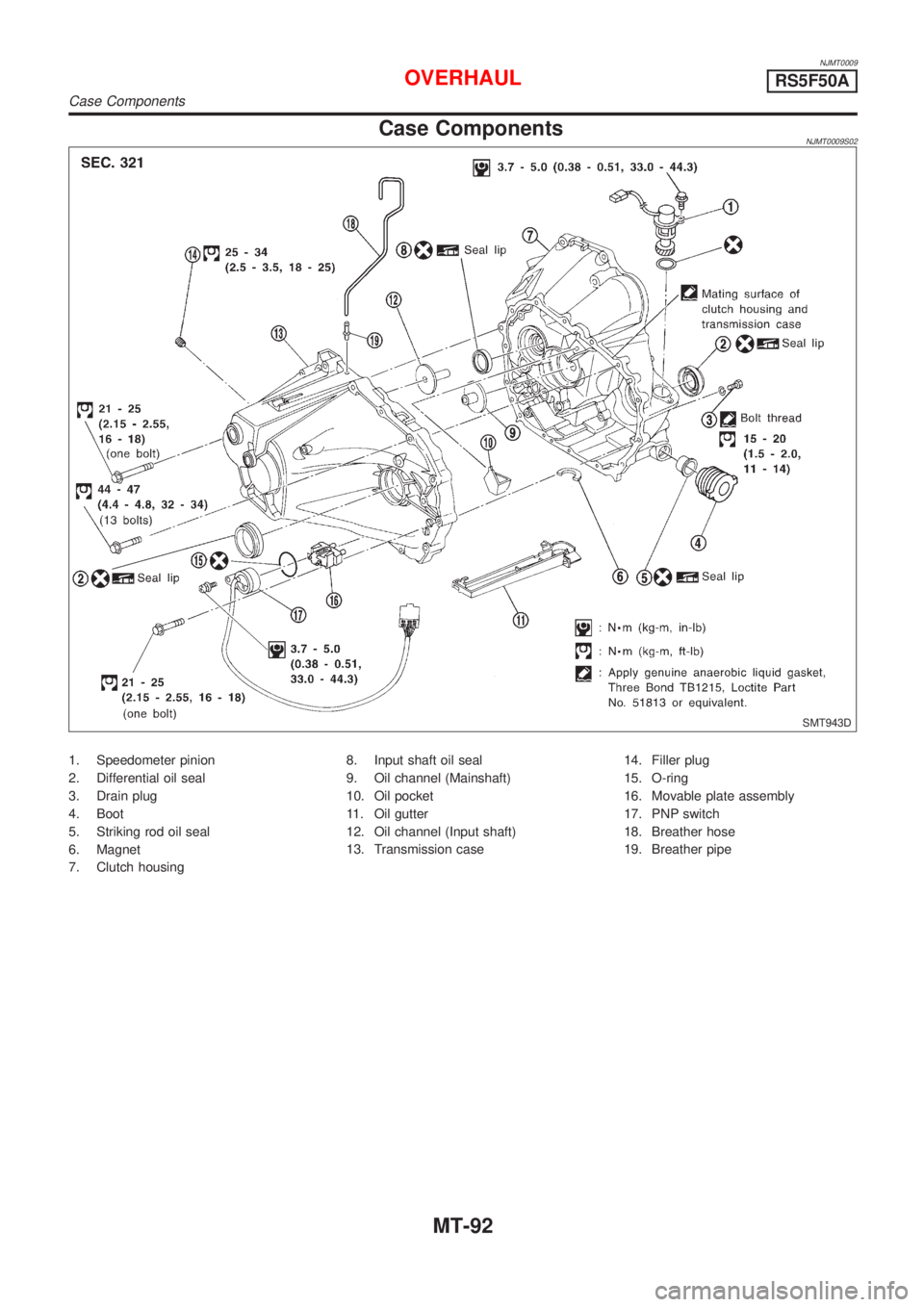
Case ComponentsNJMT0009S02
SMT943D
1. Speedometer pinion
2. Differential oil seal
3. Drain plug
4. Boot
5. Striking rod oil seal
6. Magnet
7. Clutch housing8. Input shaft oil seal
9. Oil channel (Mainshaft)
10. Oil pocket
11. Oil gutter
12. Oil channel (Input shaft)
13. Transmission case14. Filler plug
15. O-ring
16. Movable plate assembly
17. PNP switch
18. Breather hose
19. Breather pipe
OVERHAULRS5F50A
Case Components
MT-92
Page 2668 of 2898
SMT662C
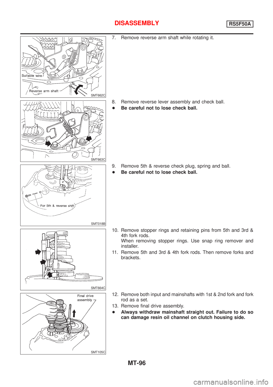
7. Remove reverse arm shaft while rotating it.
SMT663C
8. Remove reverse lever assembly and check ball.
+Be careful not to lose check ball.
SMT018B
9. Remove 5th & reverse check plug, spring and ball.
+Be careful not to lose check ball.
SMT664C
10. Remove stopper rings and retaining pins from 5th and 3rd &
4th fork rods.
When removing stopper rings. Use snap ring remover and
installer.
11. Remove 5th and 3rd & 4th fork rods. Then remove forks and
brackets.
SMT105C
12. Remove both input and mainshafts with 1st & 2nd fork and fork
rod as a set.
13. Remove final drive assembly.
+Always withdraw mainshaft straight out. Failure to do so
can damage resin oil channel on clutch housing side.
DISASSEMBLYRS5F50A
MT-96
Page 2683 of 2898
NJMT0022
Input Shaft End Play and Differential Side
Bearing Preload
NJMT0022S01If any of the following parts are replaced, adjust input shaft end
play.
+Input shaft
+Input shaft bearing
+Clutch housing
+Transmission case
If any of the following parts are replaced, adjust differential side
bearing preload.
+Differential case
+Differential side bearing
+Clutch housing
+Transmission case
SMT132AA
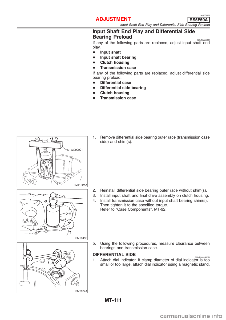
1. Remove differential side bearing outer race (transmission case
side) and shim(s).
SMT845B
2. Reinstall differential side bearing outer race without shim(s).
3. Install input shaft and final drive assembly on clutch housing.
4. Install transmission case without input shaft bearing shim(s).
Then tighten it to the specified torque.
Refer to ªCase Componentsº, MT-92.
SMT074A
5. Using the following procedures, measure clearance between
bearings and transmission case.
DIFFERENTIAL SIDENJMT0022S01011. Attach dial indicator. If clamp diameter of dial indicator is too
small or too large, attach dial indicator using a magnetic stand.
ADJUSTMENTRS5F50A
Input Shaft End Play and Differential Side Bearing Preload
MT-111
Page 2684 of 2898
SMT075AA
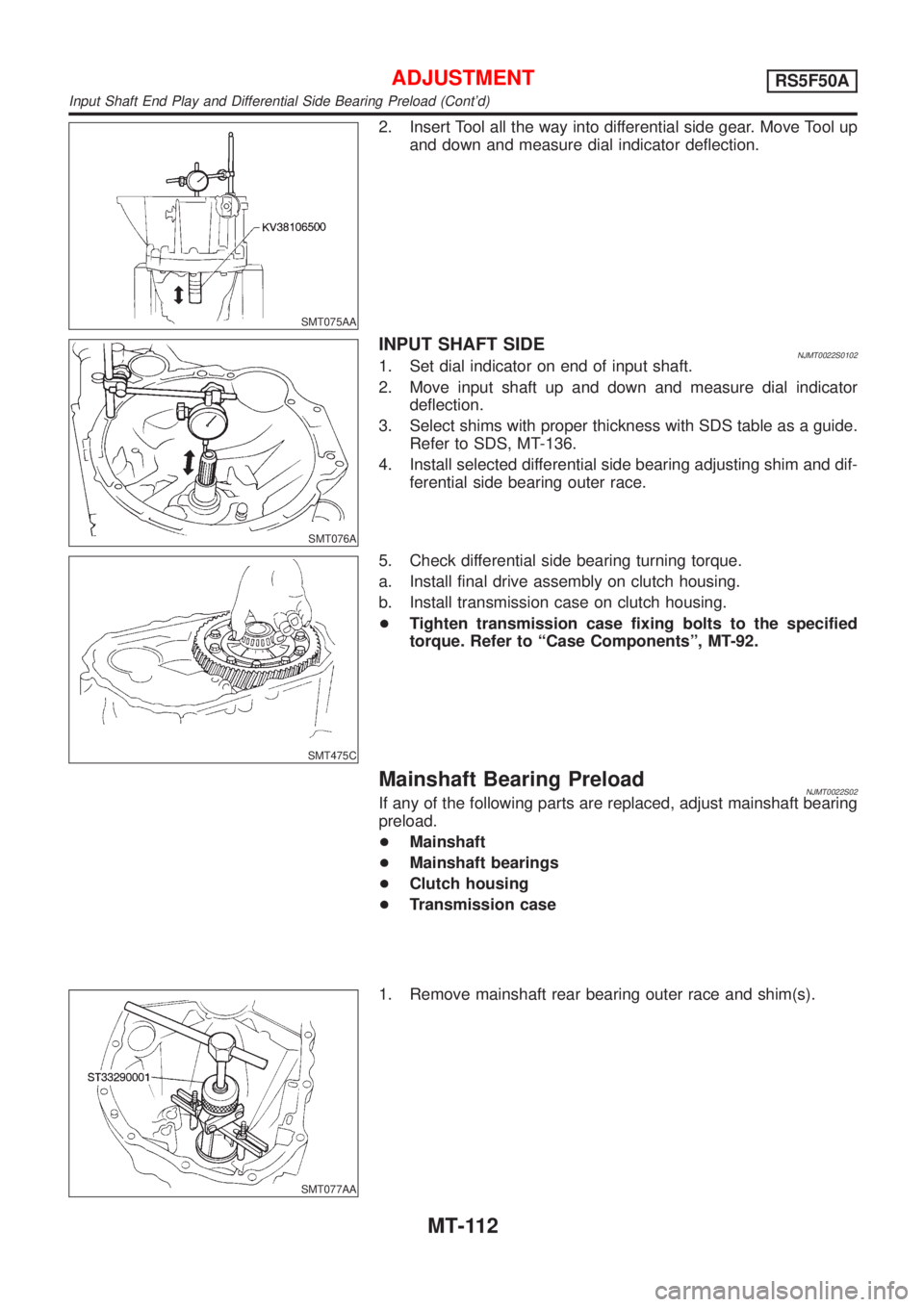
2. Insert Tool all the way into differential side gear. Move Tool up
and down and measure dial indicator deflection.
SMT076A
INPUT SHAFT SIDENJMT0022S01021. Set dial indicator on end of input shaft.
2. Move input shaft up and down and measure dial indicator
deflection.
3. Select shims with proper thickness with SDS table as a guide.
Refer to SDS, MT-136.
4. Install selected differential side bearing adjusting shim and dif-
ferential side bearing outer race.
SMT475C
5. Check differential side bearing turning torque.
a. Install final drive assembly on clutch housing.
b. Install transmission case on clutch housing.
+Tighten transmission case fixing bolts to the specified
torque. Refer to ªCase Componentsº, MT-92.
Mainshaft Bearing PreloadNJMT0022S02If any of the following parts are replaced, adjust mainshaft bearing
preload.
+Mainshaft
+Mainshaft bearings
+Clutch housing
+Transmission case
SMT077AA
1. Remove mainshaft rear bearing outer race and shim(s).
ADJUSTMENTRS5F50A
Input Shaft End Play and Differential Side Bearing Preload (Cont'd)
MT-112
Page 2685 of 2898
SMT644AA
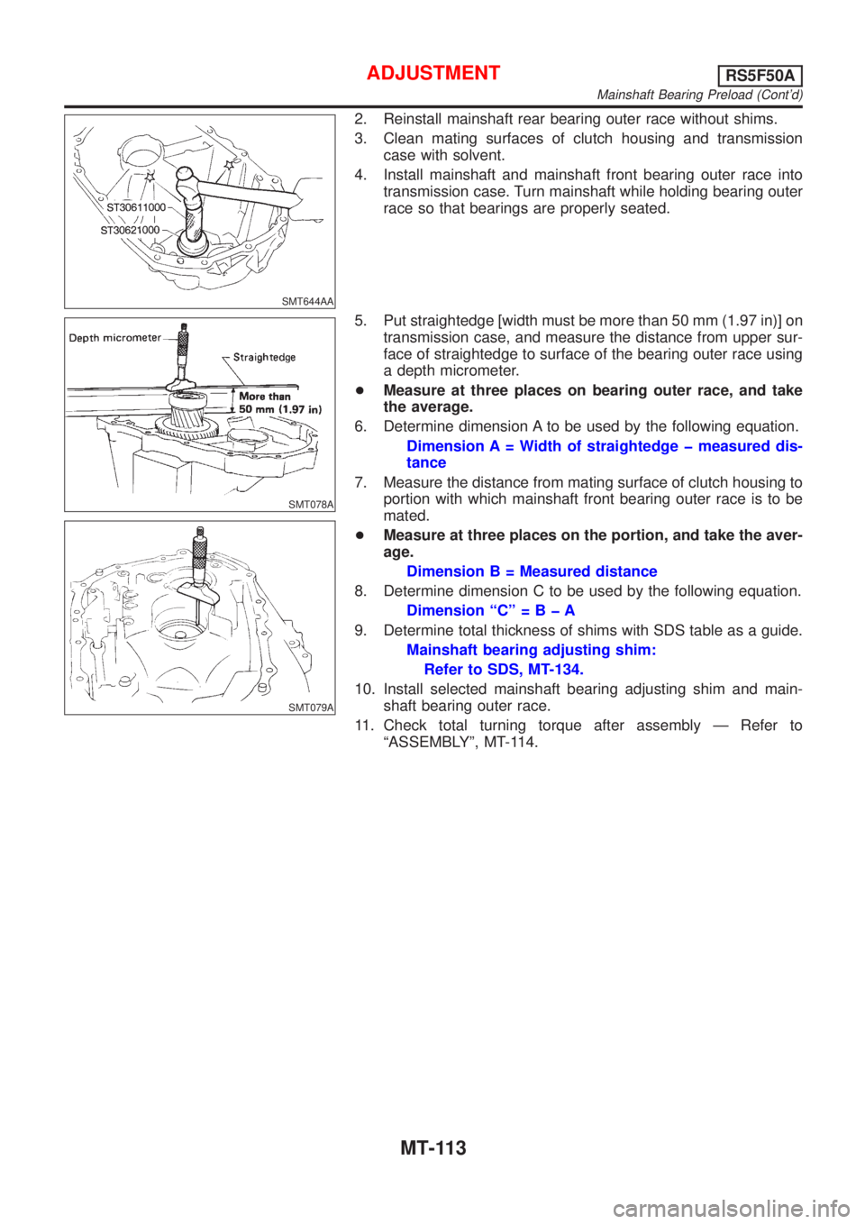
2. Reinstall mainshaft rear bearing outer race without shims.
3. Clean mating surfaces of clutch housing and transmission
case with solvent.
4. Install mainshaft and mainshaft front bearing outer race into
transmission case. Turn mainshaft while holding bearing outer
race so that bearings are properly seated.
SMT078A
SMT079A
5. Put straightedge [width must be more than 50 mm (1.97 in)] on
transmission case, and measure the distance from upper sur-
face of straightedge to surface of the bearing outer race using
a depth micrometer.
+Measure at three places on bearing outer race, and take
the average.
6. Determine dimension A to be used by the following equation.
Dimension A = Width of straightedge þ measured dis-
tance
7. Measure the distance from mating surface of clutch housing to
portion with which mainshaft front bearing outer race is to be
mated.
+Measure at three places on the portion, and take the aver-
age.
Dimension B = Measured distance
8. Determine dimension C to be used by the following equation.
Dimension ªCº=BþA
9. Determine total thickness of shims with SDS table as a guide.
Mainshaft bearing adjusting shim:
Refer to SDS, MT-134.
10. Install selected mainshaft bearing adjusting shim and main-
shaft bearing outer race.
11. Check total turning torque after assembly Ð Refer to
ªASSEMBLYº, MT-114.
ADJUSTMENTRS5F50A
Mainshaft Bearing Preload (Cont'd)
MT-113
Page 2688 of 2898
SMT667C
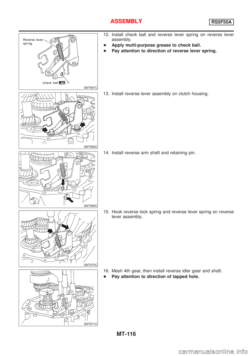
12. Install check ball and reverse lever spring on reverse lever
assembly.
+Apply multi-purpose grease to check ball.
+Pay attention to direction of reverse lever spring.
SMT668C
13. Install reverse lever assembly on clutch housing.
SMT669C
14. Install reverse arm shaft and retaining pin.
SMT670C
15. Hook reverse lock spring and reverse lever spring on reverse
lever assembly.
SMT671C
16. Mesh 4th gear, then install reverse idler gear and shaft.
+Pay attention to direction of tapped hole.
ASSEMBLYRS5F50A
MT-116
Page 2689 of 2898
SMT070A
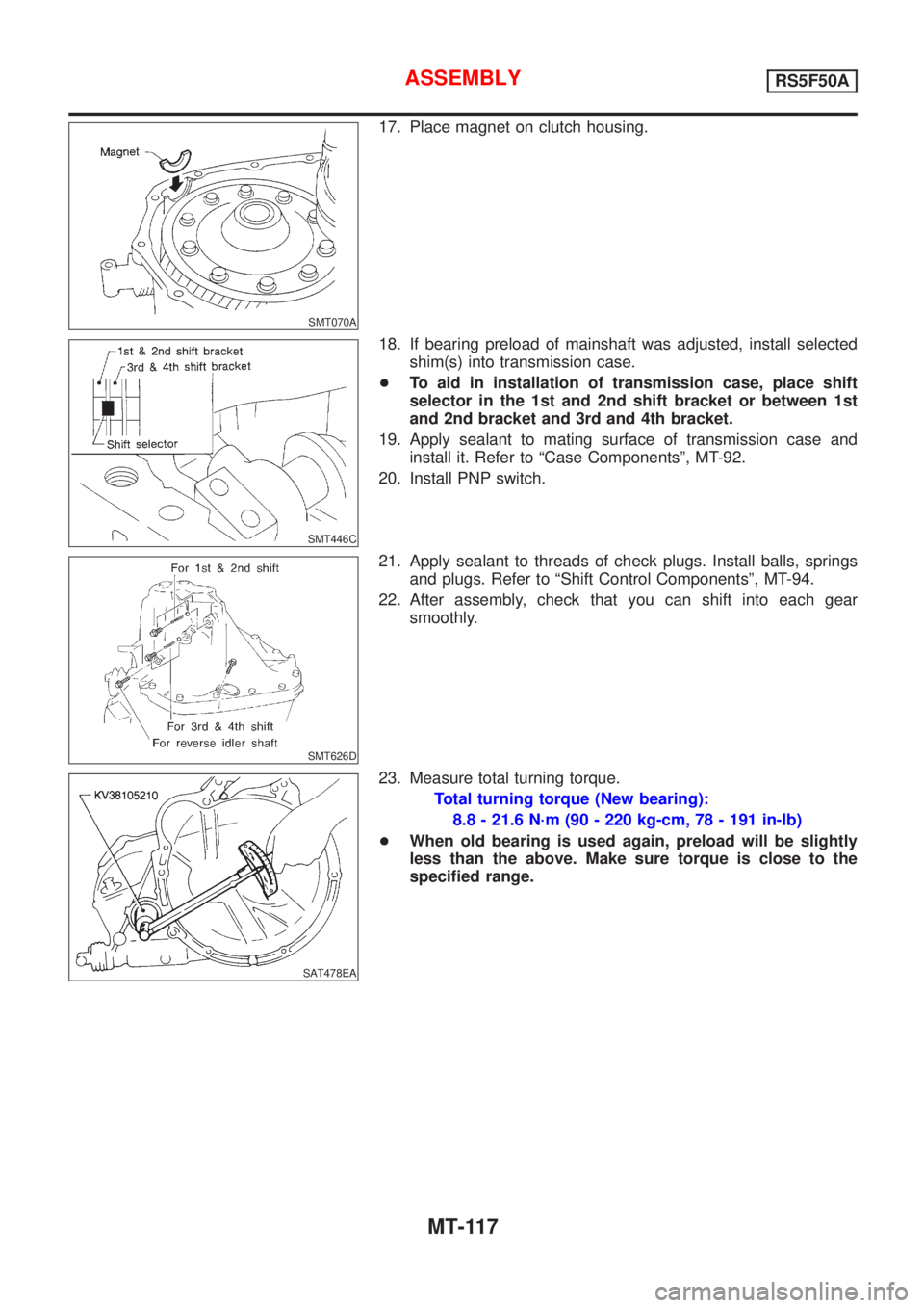
17. Place magnet on clutch housing.
SMT446C
18. If bearing preload of mainshaft was adjusted, install selected
shim(s) into transmission case.
+To aid in installation of transmission case, place shift
selector in the 1st and 2nd shift bracket or between 1st
and 2nd bracket and 3rd and 4th bracket.
19. Apply sealant to mating surface of transmission case and
install it. Refer to ªCase Componentsº, MT-92.
20. Install PNP switch.
SMT626D
21. Apply sealant to threads of check plugs. Install balls, springs
and plugs. Refer to ªShift Control Componentsº, MT-94.
22. After assembly, check that you can shift into each gear
smoothly.
SAT478EA
23. Measure total turning torque.
Total turning torque (New bearing):
8.8 - 21.6 N´m (90 - 220 kg-cm, 78 - 191 in-lb)
+When old bearing is used again, preload will be slightly
less than the above. Make sure torque is close to the
specified range.
ASSEMBLYRS5F50A
MT-117
Page 2797 of 2898
STARTING & CHARGING SYSTEMS
SECTION
SC
CONTENTS
PRECAUTIONS...............................................................2
Supplemental Restraint System (SRS)²AIR
BAG²and²SEAT BELT PRE-TENSIONER²...............2
Wiring Diagrams and Trouble Diagnoses....................2
BATTERY.........................................................................3
How to Handle Battery ................................................3
METHODS OF PREVENTING OVER-DISCHARGE......3
CHECKING ELECTROLYTE LEVEL............................3
SPECIFIC GRAVITY CHECK......................................4
Battery Test and Charging Chart .................................6
CHART I...................................................................6
CHART II..................................................................7
A: SLOW CHARGE....................................................8
B: STANDARD CHARGE..........................................10
C: QUICK CHARGE................................................. 11
STARTING SYSTEM.....................................................13
System Description ....................................................13
M/T MODELS..........................................................13
A/T MODELS...........................................................13
Wiring Diagram - START -/Sedan .............................14
M/T MODELS..........................................................14
A/T MODELS...........................................................15
Wiring Diagram - START -/Hatchback.......................16
Trouble Diagnoses.....................................................17
Construction ...............................................................18
Removal and Installation ...........................................21
REMOVAL...............................................................21
INSTALLATION........................................................21
Inspection...................................................................21
MAGNETIC SWITCH CHECK...................................21
PINION/CLUTCH CHECK.........................................21
BRUSH CHECK.......................................................22
YOKE CHECK.........................................................23
ARMATURE CHECK................................................23
Assembly ...................................................................24
PINION PROTRUSION LENGTH ADJUSTMENT........24
CHARGING SYSTEM....................................................26
System Description ....................................................26
SEDAN...................................................................26
HATCHBACK...........................................................26
Wiring Diagram - CHARGE -/Sedan .........................27
GASOLINE ENGINE MODELS..................................27
DIESEL ENGINE MODELS.......................................28
Wiring Diagram - CHARGE -/Hatchback...................29
Trouble Diagnoses.....................................................30
WITH IC REGULATOR.............................................30
MALFUNCTION INDICATOR....................................30
Construction ...............................................................31
Removal and Installation ...........................................34
REMOVAL (QG ENGINE).........................................34
REMOVAL (YD ENGINE)..........................................34
INSTALLATION........................................................35
Disassembly...............................................................35
REAR COVER.........................................................35
REAR BEARING......................................................35
Inspection...................................................................35
ROTOR CHECK......................................................35
BRUSH CHECK.......................................................36
STATOR CHECK.....................................................36
Assembly ...................................................................36
RING FITTING IN REAR BEARING...........................36
REAR COVER INSTALLATION.................................37
SERVICE DATA AND SPECIFICATIONS (SDS).........38
Battery........................................................................38
Starter ........................................................................38
Alternator ...................................................................39
Page 2817 of 2898
SEL909TA
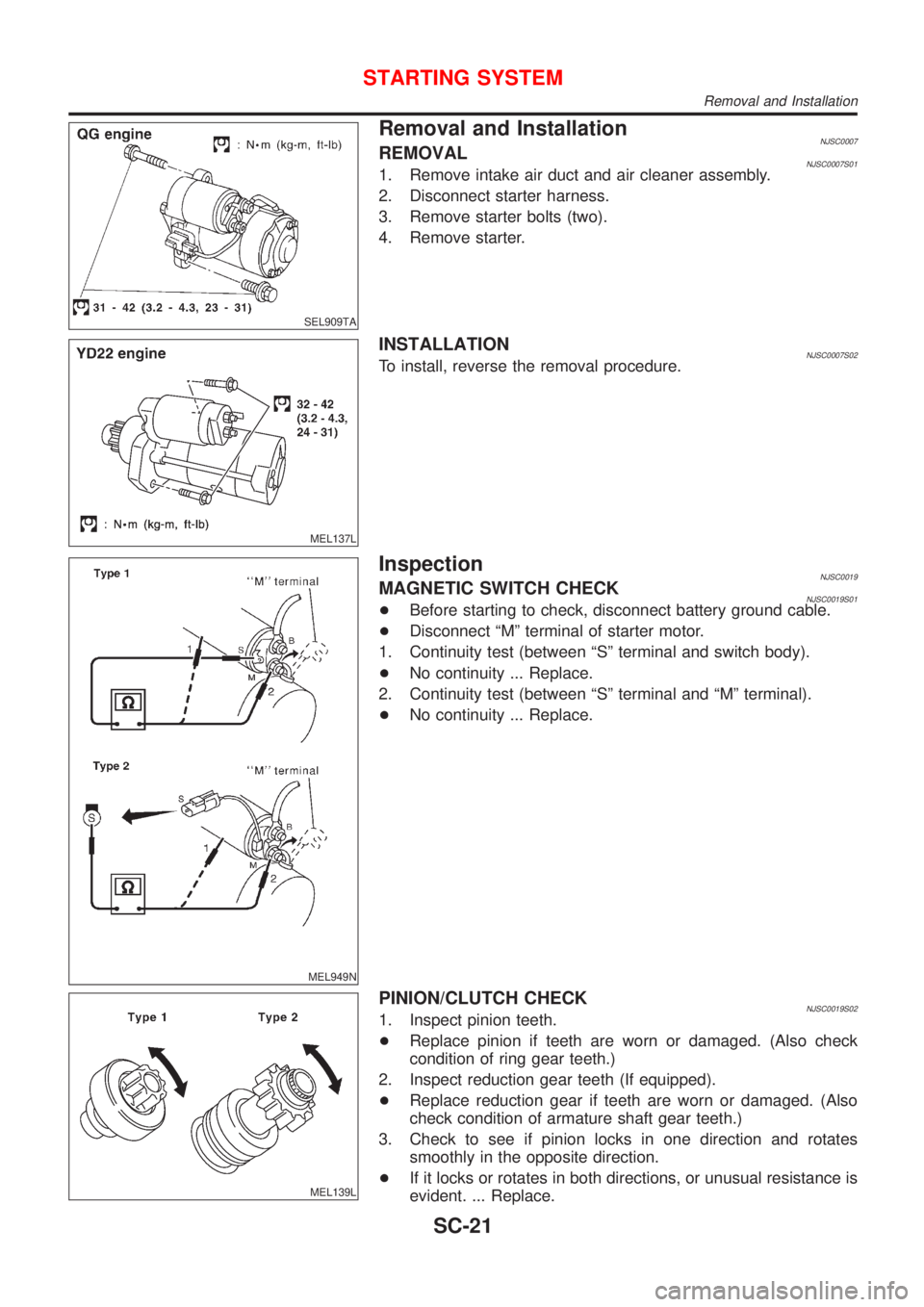
Removal and InstallationNJSC0007REMOVALNJSC0007S011. Remove intake air duct and air cleaner assembly.
2. Disconnect starter harness.
3. Remove starter bolts (two).
4. Remove starter.
MEL137L
INSTALLATIONNJSC0007S02To install, reverse the removal procedure.
MEL949N
InspectionNJSC0019MAGNETIC SWITCH CHECKNJSC0019S01+Before starting to check, disconnect battery ground cable.
+Disconnect ªMº terminal of starter motor.
1. Continuity test (between ªSº terminal and switch body).
+No continuity ... Replace.
2. Continuity test (between ªSº terminal and ªMº terminal).
+No continuity ... Replace.
MEL139L
PINION/CLUTCH CHECKNJSC0019S021. Inspect pinion teeth.
+Replace pinion if teeth are worn or damaged. (Also check
condition of ring gear teeth.)
2. Inspect reduction gear teeth (If equipped).
+Replace reduction gear if teeth are worn or damaged. (Also
check condition of armature shaft gear teeth.)
3. Check to see if pinion locks in one direction and rotates
smoothly in the opposite direction.
+If it locks or rotates in both directions, or unusual resistance is
evident. ... Replace.
STARTING SYSTEM
Removal and Installation
SC-21