clutch NISSAN ALMERA 2001 Service Manual
[x] Cancel search | Manufacturer: NISSAN, Model Year: 2001, Model line: ALMERA, Model: NISSAN ALMERA 2001Pages: 2898, PDF Size: 60.76 MB
Page 2570 of 2898
NJMA0006
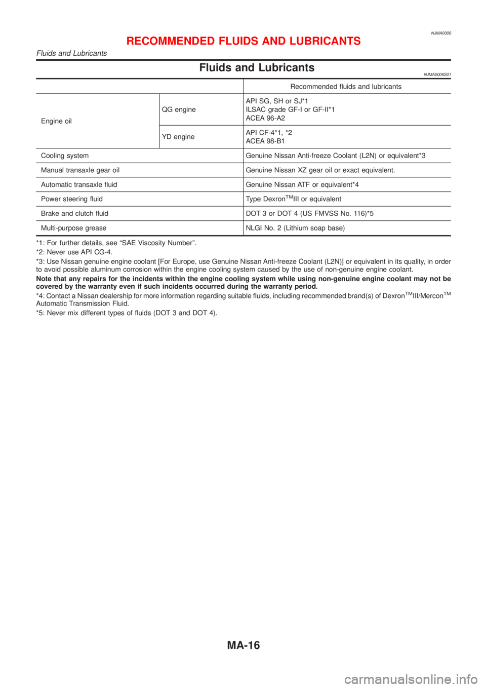
Fluids and LubricantsNJMA0006S01
Recommended fluids and lubricants
Engine oilQG engineAPI SG, SH or SJ*1
ILSAC grade GF-I or GF-II*1
ACEA 96-A2
YD engineAPI CF-4*1, *2
ACEA 98-B1
Cooling system Genuine Nissan Anti-freeze Coolant (L2N) or equivalent*3
Manual transaxle gear oil Genuine Nissan XZ gear oil or exact equivalent.
Automatic transaxle fluid Genuine Nissan ATF or equivalent*4
Power steering fluid Type Dexron
TMIII or equivalent
Brake and clutch fluid DOT 3 or DOT 4 (US FMVSS No. 116)*5
Multi-purpose grease NLGI No. 2 (Lithium soap base)
*1: For further details, see ªSAE Viscosity Numberº.
*2: Never use API CG-4.
*3: Use Nissan genuine engine coolant [For Europe, use Genuine Nissan Anti-freeze Coolant (L2N)] or equivalent in its quality, in order
to avoid possible aluminum corrosion within the engine cooling system caused by the use of non-genuine engine coolant.
Note that any repairs for the incidents within the engine cooling system while using non-genuine engine coolant may not be
covered by the warranty even if such incidents occurred during the warranty period.
*4: Contact a Nissan dealership for more information regarding suitable fluids, including recommended brand(s) of Dexron
TMIII/MerconTM
Automatic Transmission Fluid.
*5: Never mix different types of fluids (DOT 3 and DOT 4).
RECOMMENDED FLUIDS AND LUBRICANTS
Fluids and Lubricants
MA-16
Page 2574 of 2898
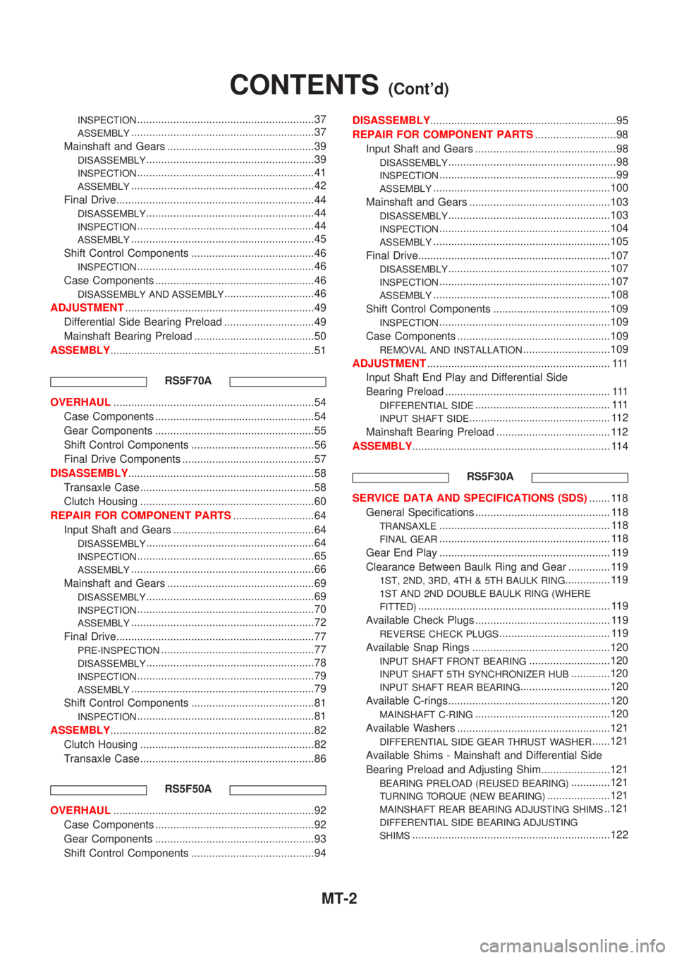
INSPECTION...........................................................37
ASSEMBLY.............................................................37
Mainshaft and Gears .................................................39
DISASSEMBLY........................................................39
INSPECTION...........................................................41
ASSEMBLY.............................................................42
Final Drive..................................................................44
DISASSEMBLY........................................................44
INSPECTION...........................................................44
ASSEMBLY.............................................................45
Shift Control Components .........................................46
INSPECTION...........................................................46
Case Components .....................................................46
DISASSEMBLY AND ASSEMBLY..............................46
ADJUSTMENT...............................................................49
Differential Side Bearing Preload ..............................49
Mainshaft Bearing Preload ........................................50
ASSEMBLY....................................................................51
RS5F70A
OVERHAUL...................................................................54
Case Components .....................................................54
Gear Components .....................................................55
Shift Control Components .........................................56
Final Drive Components ............................................57
DISASSEMBLY..............................................................58
Transaxle Case ..........................................................58
Clutch Housing ..........................................................60
REPAIR FOR COMPONENT PARTS...........................64
Input Shaft and Gears ...............................................64
DISASSEMBLY........................................................64
INSPECTION...........................................................65
ASSEMBLY.............................................................66
Mainshaft and Gears .................................................69
DISASSEMBLY........................................................69
INSPECTION...........................................................70
ASSEMBLY.............................................................72
Final Drive..................................................................77
PRE-INSPECTION...................................................77
DISASSEMBLY........................................................78
INSPECTION...........................................................79
ASSEMBLY.............................................................79
Shift Control Components .........................................81
INSPECTION...........................................................81
ASSEMBLY....................................................................82
Clutch Housing ..........................................................82
Transaxle Case ..........................................................86
RS5F50A
OVERHAUL...................................................................92
Case Components .....................................................92
Gear Components .....................................................93
Shift Control Components .........................................94DISASSEMBLY..............................................................95
REPAIR FOR COMPONENT PARTS...........................98
Input Shaft and Gears ...............................................98
DISASSEMBLY........................................................98
INSPECTION...........................................................99
ASSEMBLY...........................................................100
Mainshaft and Gears ...............................................103
DISASSEMBLY......................................................103
INSPECTION.........................................................104
ASSEMBLY...........................................................105
Final Drive................................................................107
DISASSEMBLY......................................................107
INSPECTION.........................................................107
ASSEMBLY...........................................................108
Shift Control Components .......................................109
INSPECTION.........................................................109
Case Components ...................................................109
REMOVAL AND INSTALLATION.............................109
ADJUSTMENT............................................................. 111
Input Shaft End Play and Differential Side
Bearing Preload ....................................................... 111
DIFFERENTIAL SIDE............................................. 111
INPUT SHAFT SIDE............................................... 112
Mainshaft Bearing Preload ...................................... 112
ASSEMBLY.................................................................. 114
RS5F30A
SERVICE DATA AND SPECIFICATIONS (SDS)....... 118
General Specifications ............................................. 118
TRANSAXLE......................................................... 118
FINAL GEAR......................................................... 118
Gear End Play ......................................................... 119
Clearance Between Baulk Ring and Gear .............. 119
1ST, 2ND, 3RD, 4TH & 5TH BAULK RING............... 119
1ST AND 2ND DOUBLE BAULK RING (WHERE
FITTED)
................................................................ 119
Available Check Plugs ............................................. 119
REVERSE CHECK PLUGS..................................... 119
Available Snap Rings ..............................................120
INPUT SHAFT FRONT BEARING...........................120
INPUT SHAFT 5TH SYNCHRONIZER HUB.............120
INPUT SHAFT REAR BEARING..............................120
Available C-rings......................................................120
MAINSHAFT C-RING.............................................120
Available Washers ...................................................121
DIFFERENTIAL SIDE GEAR THRUST WASHER......121
Available Shims - Mainshaft and Differential Side
Bearing Preload and Adjusting Shim.......................121
BEARING PRELOAD (REUSED BEARING).............121
TURNING TORQUE (NEW BEARING).....................121
MAINSHAFT REAR BEARING ADJUSTING SHIMS..121
DIFFERENTIAL SIDE BEARING ADJUSTING
SHIMS
..................................................................122
CONTENTS(Cont'd)
MT-2
Page 2580 of 2898
Tool number
Tool nameDescription
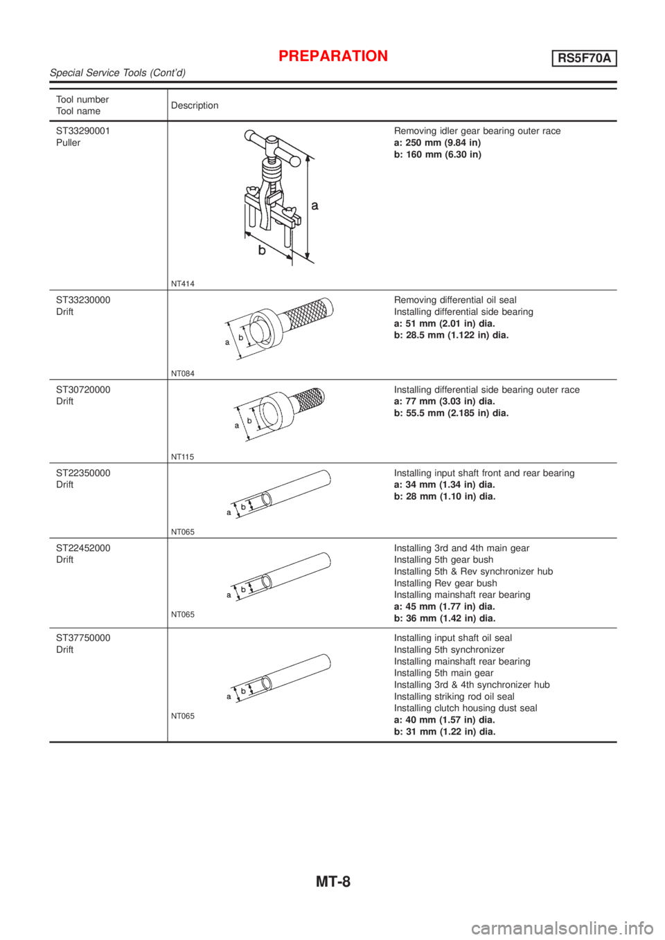
ST33290001
Puller
NT414
Removing idler gear bearing outer race
a: 250 mm (9.84 in)
b: 160 mm (6.30 in)
ST33230000
Drift
NT084
Removing differential oil seal
Installing differential side bearing
a: 51 mm (2.01 in) dia.
b: 28.5 mm (1.122 in) dia.
ST30720000
Drift
NT115
Installing differential side bearing outer race
a: 77 mm (3.03 in) dia.
b: 55.5 mm (2.185 in) dia.
ST22350000
Drift
NT065
Installing input shaft front and rear bearing
a: 34 mm (1.34 in) dia.
b: 28 mm (1.10 in) dia.
ST22452000
Drift
NT065
Installing 3rd and 4th main gear
Installing 5th gear bush
Installing 5th & Rev synchronizer hub
Installing Rev gear bush
Installing mainshaft rear bearing
a: 45 mm (1.77 in) dia.
b: 36 mm (1.42 in) dia.
ST37750000
Drift
NT065
Installing input shaft oil seal
Installing 5th synchronizer
Installing mainshaft rear bearing
Installing 5th main gear
Installing 3rd & 4th synchronizer hub
Installing striking rod oil seal
Installing clutch housing dust seal
a: 40 mm (1.57 in) dia.
b: 31 mm (1.22 in) dia.
PREPARATIONRS5F70A
Special Service Tools (Cont'd)
MT-8
Page 2595 of 2898
NJMT0008
SMT928D
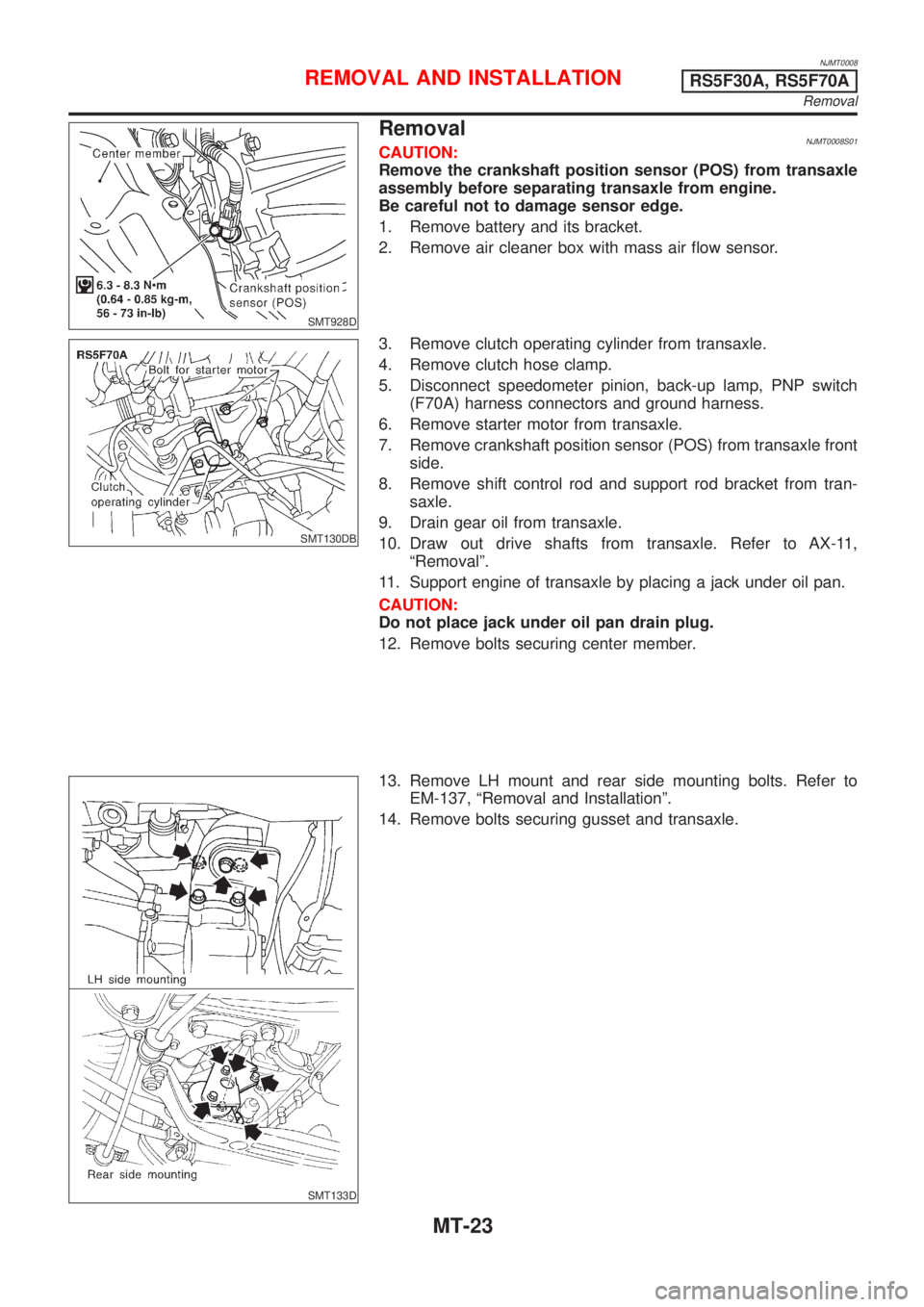
RemovalNJMT0008S01CAUTION:
Remove the crankshaft position sensor (POS) from transaxle
assembly before separating transaxle from engine.
Be careful not to damage sensor edge.
1. Remove battery and its bracket.
2. Remove air cleaner box with mass air flow sensor.
SMT130DB
3. Remove clutch operating cylinder from transaxle.
4. Remove clutch hose clamp.
5. Disconnect speedometer pinion, back-up lamp, PNP switch
(F70A) harness connectors and ground harness.
6. Remove starter motor from transaxle.
7. Remove crankshaft position sensor (POS) from transaxle front
side.
8. Remove shift control rod and support rod bracket from tran-
saxle.
9. Drain gear oil from transaxle.
10. Draw out drive shafts from transaxle. Refer to AX-11,
ªRemovalº.
11. Support engine of transaxle by placing a jack under oil pan.
CAUTION:
Do not place jack under oil pan drain plug.
12. Remove bolts securing center member.
SMT133D
13. Remove LH mount and rear side mounting bolts. Refer to
EM-137, ªRemoval and Installationº.
14. Remove bolts securing gusset and transaxle.
REMOVAL AND INSTALLATIONRS5F30A, RS5F70A
Removal
MT-23
Page 2596 of 2898
SMT652C
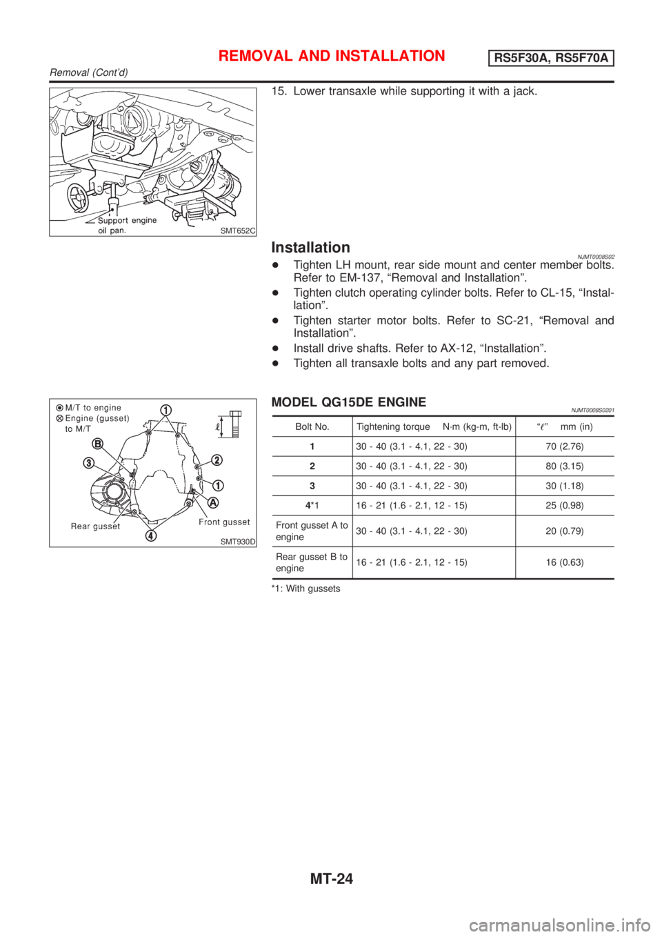
15. Lower transaxle while supporting it with a jack.
InstallationNJMT0008S02+Tighten LH mount, rear side mount and center member bolts.
Refer to EM-137, ªRemoval and Installationº.
+Tighten clutch operating cylinder bolts. Refer to CL-15, ªInstal-
lationº.
+Tighten starter motor bolts. Refer to SC-21, ªRemoval and
Installationº.
+Install drive shafts. Refer to AX-12, ªInstallationº.
+Tighten all transaxle bolts and any part removed.
SMT930D
MODEL QG15DE ENGINENJMT0008S0201
Bolt No. Tightening torque N´m (kg-m, ft-lb) ª!º mm (in)
130 - 40 (3.1 - 4.1, 22 - 30) 70 (2.76)
230 - 40 (3.1 - 4.1, 22 - 30) 80 (3.15)
330 - 40 (3.1 - 4.1, 22 - 30) 30 (1.18)
4*1 16 - 21 (1.6 - 2.1, 12 - 15) 25 (0.98)
Front gusset A to
engine30 - 40 (3.1 - 4.1, 22 - 30) 20 (0.79)
Rear gusset B to
engine16 - 21 (1.6 - 2.1, 12 - 15) 16 (0.63)
*1: With gussets
REMOVAL AND INSTALLATIONRS5F30A, RS5F70A
Removal (Cont'd)
MT-24
Page 2598 of 2898
NJMT0090
SMT928D
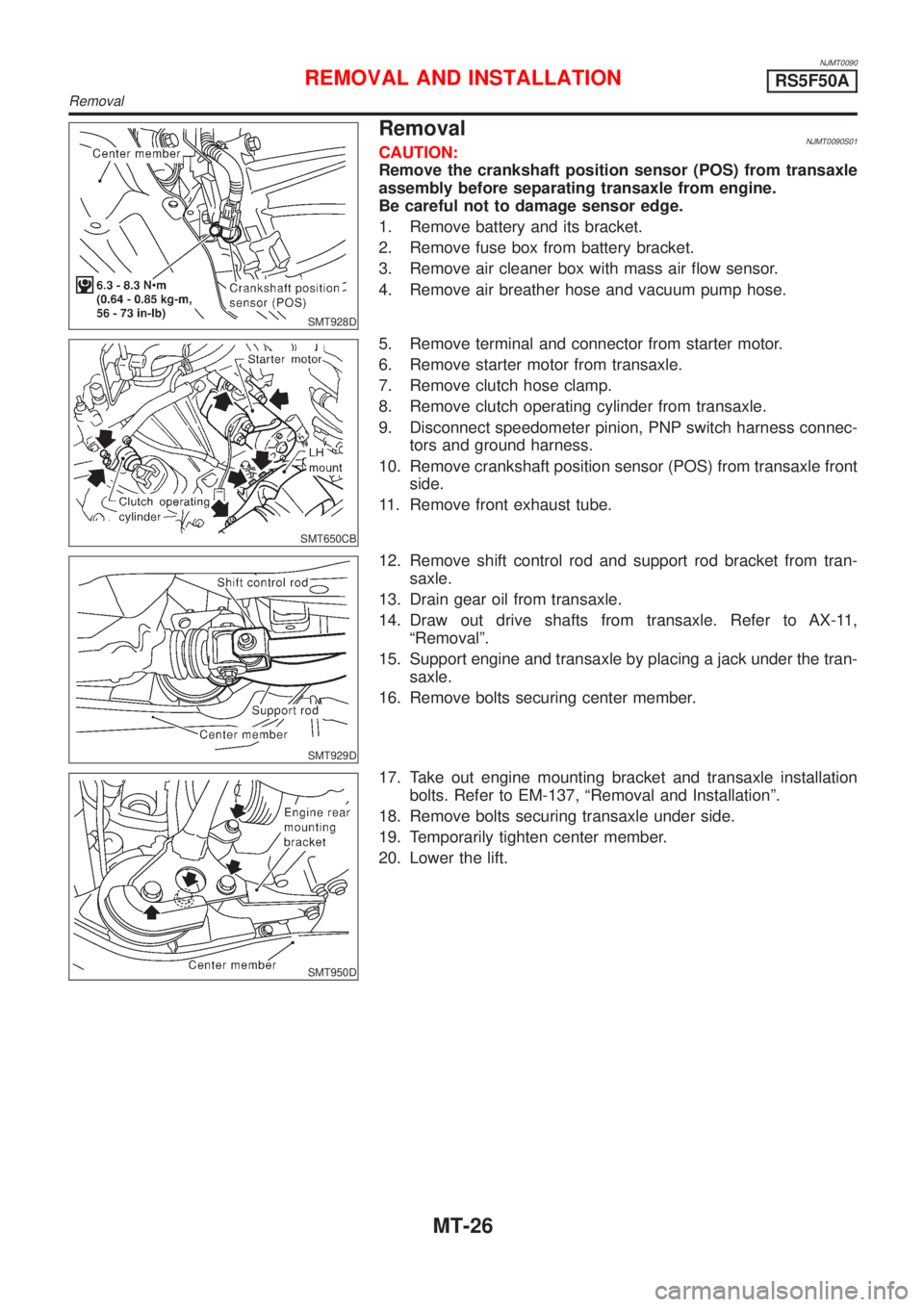
RemovalNJMT0090S01CAUTION:
Remove the crankshaft position sensor (POS) from transaxle
assembly before separating transaxle from engine.
Be careful not to damage sensor edge.
1. Remove battery and its bracket.
2. Remove fuse box from battery bracket.
3. Remove air cleaner box with mass air flow sensor.
4. Remove air breather hose and vacuum pump hose.
SMT650CB
5. Remove terminal and connector from starter motor.
6. Remove starter motor from transaxle.
7. Remove clutch hose clamp.
8. Remove clutch operating cylinder from transaxle.
9. Disconnect speedometer pinion, PNP switch harness connec-
tors and ground harness.
10. Remove crankshaft position sensor (POS) from transaxle front
side.
11. Remove front exhaust tube.
SMT929D
12. Remove shift control rod and support rod bracket from tran-
saxle.
13. Drain gear oil from transaxle.
14. Draw out drive shafts from transaxle. Refer to AX-11,
ªRemovalº.
15. Support engine and transaxle by placing a jack under the tran-
saxle.
16. Remove bolts securing center member.
SMT950D
17. Take out engine mounting bracket and transaxle installation
bolts. Refer to EM-137, ªRemoval and Installationº.
18. Remove bolts securing transaxle under side.
19. Temporarily tighten center member.
20. Lower the lift.
REMOVAL AND INSTALLATIONRS5F50A
Removal
MT-26
Page 2599 of 2898
SMT940D
SMT951D
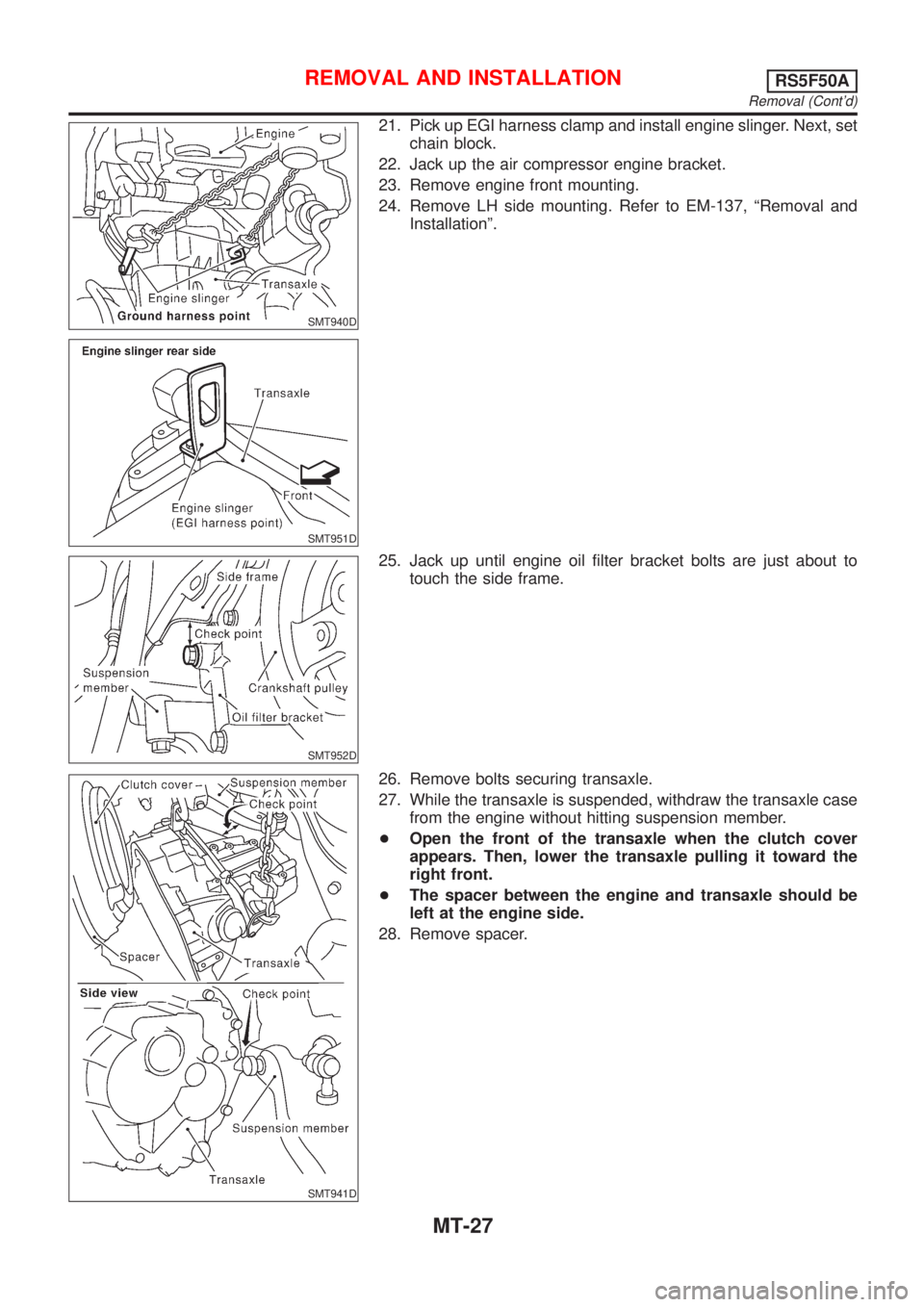
21. Pick up EGI harness clamp and install engine slinger. Next, set
chain block.
22. Jack up the air compressor engine bracket.
23. Remove engine front mounting.
24. Remove LH side mounting. Refer to EM-137, ªRemoval and
Installationº.
SMT952D
25. Jack up until engine oil filter bracket bolts are just about to
touch the side frame.
SMT941D
26. Remove bolts securing transaxle.
27. While the transaxle is suspended, withdraw the transaxle case
from the engine without hitting suspension member.
+Open the front of the transaxle when the clutch cover
appears. Then, lower the transaxle pulling it toward the
right front.
+The spacer between the engine and transaxle should be
left at the engine side.
28. Remove spacer.
REMOVAL AND INSTALLATIONRS5F50A
Removal (Cont'd)
MT-27
Page 2600 of 2898
SMT941D
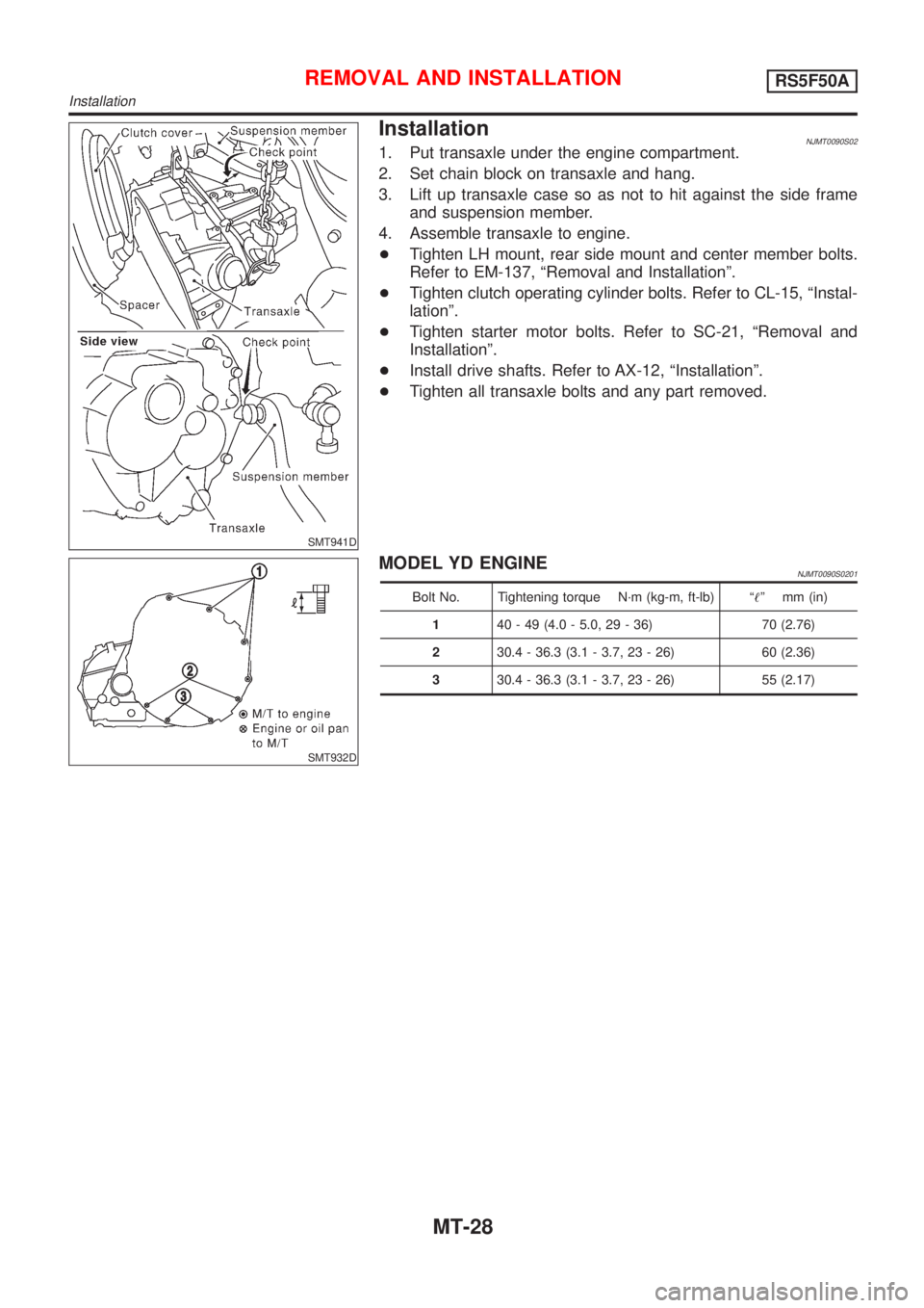
InstallationNJMT0090S021. Put transaxle under the engine compartment.
2. Set chain block on transaxle and hang.
3. Lift up transaxle case so as not to hit against the side frame
and suspension member.
4. Assemble transaxle to engine.
+Tighten LH mount, rear side mount and center member bolts.
Refer to EM-137, ªRemoval and Installationº.
+Tighten clutch operating cylinder bolts. Refer to CL-15, ªInstal-
lationº.
+Tighten starter motor bolts. Refer to SC-21, ªRemoval and
Installationº.
+Install drive shafts. Refer to AX-12, ªInstallationº.
+Tighten all transaxle bolts and any part removed.
SMT932D
MODEL YD ENGINENJMT0090S0201
Bolt No. Tightening torque N´m (kg-m, ft-lb) ª!º mm (in)
140 - 49 (4.0 - 5.0, 29 - 36) 70 (2.76)
230.4 - 36.3 (3.1 - 3.7, 23 - 26) 60 (2.36)
330.4 - 36.3 (3.1 - 3.7, 23 - 26) 55 (2.17)
REMOVAL AND INSTALLATIONRS5F50A
Installation
MT-28
Page 2602 of 2898
NJMT0039
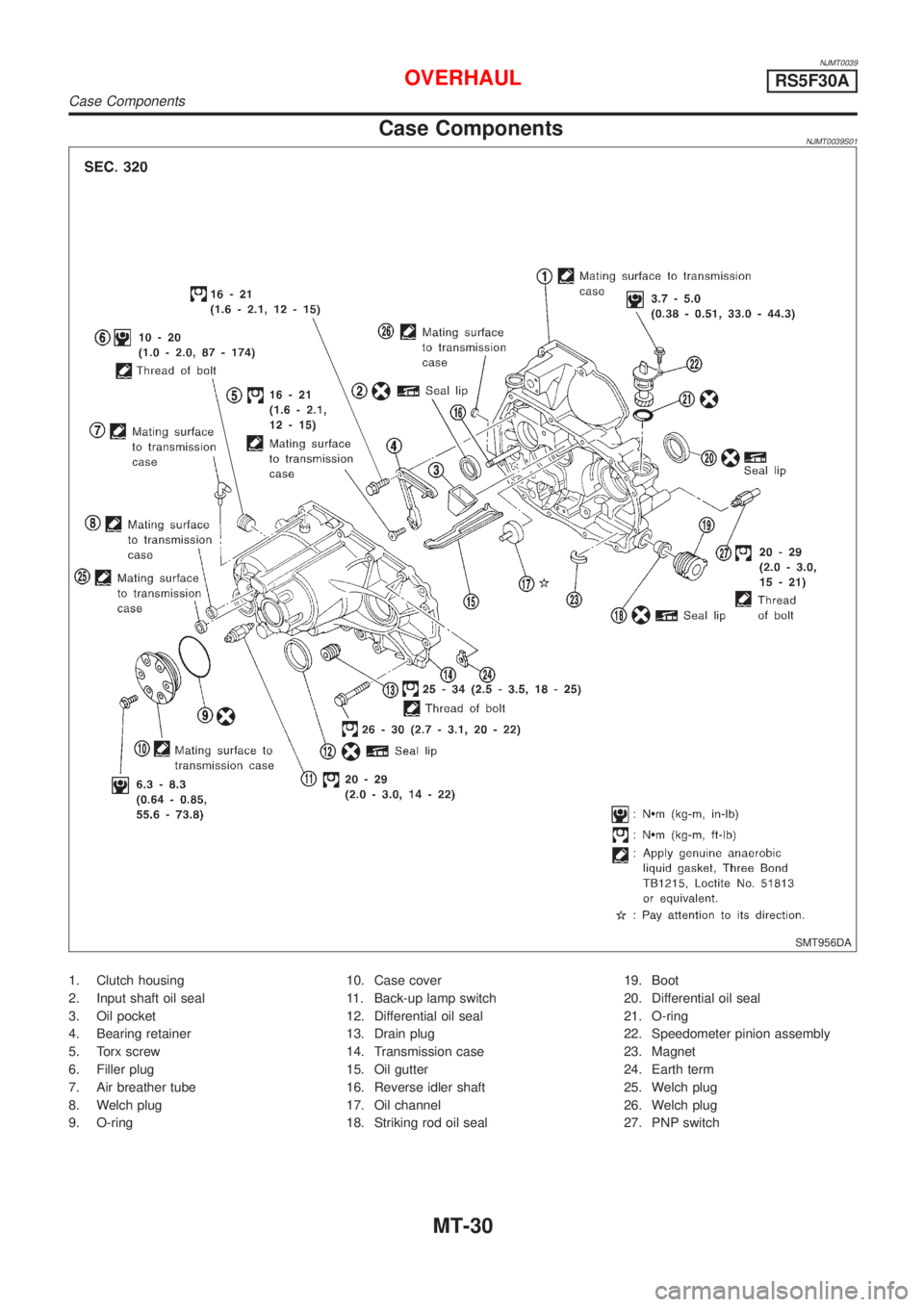
Case ComponentsNJMT0039S01
SMT956DA
1. Clutch housing
2. Input shaft oil seal
3. Oil pocket
4. Bearing retainer
5. Torx screw
6. Filler plug
7. Air breather tube
8. Welch plug
9. O-ring10. Case cover
11. Back-up lamp switch
12. Differential oil seal
13. Drain plug
14. Transmission case
15. Oil gutter
16. Reverse idler shaft
17. Oil channel
18. Striking rod oil seal19. Boot
20. Differential oil seal
21. O-ring
22. Speedometer pinion assembly
23. Magnet
24. Earth term
25. Welch plug
26. Welch plug
27. PNP switch
OVERHAULRS5F30A
Case Components
MT-30
Page 2605 of 2898
NJMT0040
SMT571
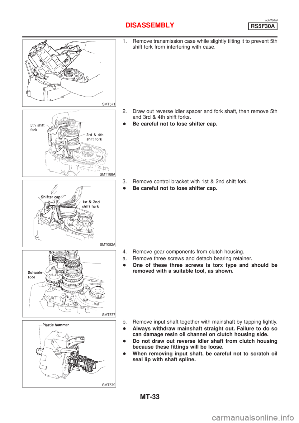
1. Remove transmission case while slightly tilting it to prevent 5th
shift fork from interfering with case.
SMT188A
2. Draw out reverse idler spacer and fork shaft, then remove 5th
and 3rd & 4th shift forks.
+Be careful not to lose shifter cap.
SMT082A
3. Remove control bracket with 1st & 2nd shift fork.
+Be careful not to lose shifter cap.
SMT577
4. Remove gear components from clutch housing.
a. Remove three screws and detach bearing retainer.
+One of these three screws is torx type and should be
removed with a suitable tool, as shown.
SMT579
b. Remove input shaft together with mainshaft by tapping lightly.
+Always withdraw mainshaft straight out. Failure to do so
can damage resin oil channel on clutch housing side.
+Do not draw out reverse idler shaft from clutch housing
because these fittings will be loose.
+When removing input shaft, be careful not to scratch oil
seal lip with shaft spline.
DISASSEMBLYRS5F30A
MT-33