oil filter NISSAN ALMERA 2001 Owner's Manual
[x] Cancel search | Manufacturer: NISSAN, Model Year: 2001, Model line: ALMERA, Model: NISSAN ALMERA 2001Pages: 2898, PDF Size: 60.76 MB
Page 2145 of 2898
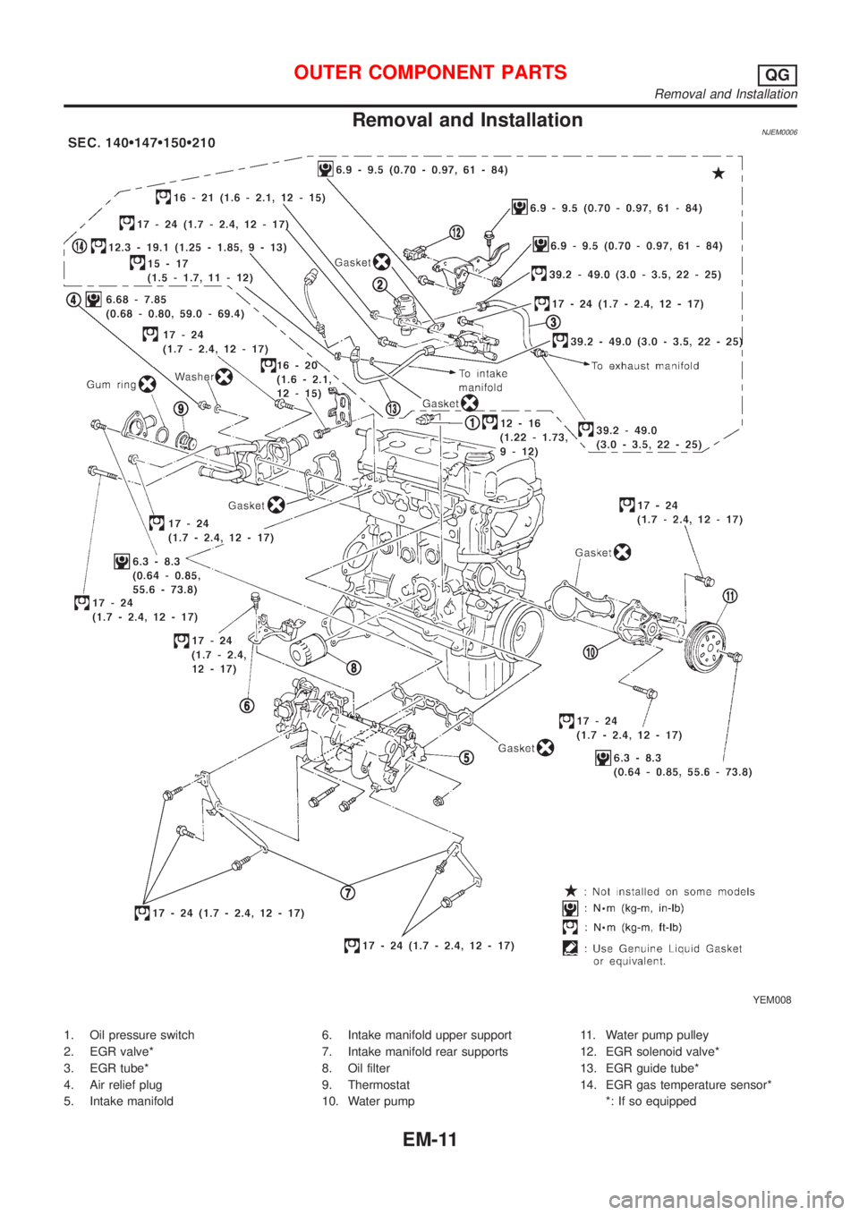
Removal and InstallationNJEM0006
YEM008
1. Oil pressure switch
2. EGR valve*
3. EGR tube*
4. Air relief plug
5. Intake manifold6. Intake manifold upper support
7. Intake manifold rear supports
8. Oil filter
9. Thermostat
10. Water pump11. Water pump pulley
12. EGR solenoid valve*
13. EGR guide tube*
14. EGR gas temperature sensor*
*: If so equipped
OUTER COMPONENT PARTSQG
Removal and Installation
EM-11
Page 2234 of 2898
REMOVALNJEM0094S011. Remove engine and transaxle assembly. Refer to EM-137,
ªENGINE ASSEMBLYº.
2. Remove transaxle from engine. Place engine onto engine
stand (SST). Refer to EM-141, ªCYLINDER BLOCKº, ªDisas-
semblyº.
3. Remove the following parts:
+Oil pan (upper and lower)
Refer to EM-89, ªOIL PANº.
+Oil filter bracket
Refer to LC-32, ªOil Filter Bracketº.
+Injection tube
Refer to EC-614, ªInjection Tube and Injection Nozzleº.
4. Remove secondary timing chain and associated parts.
Refer to EM-94, ªSecondary Timing Chainº.
5. When removing rear chain case, remove camshaft sprockets.
Refer to EM-120, ªCAMSHAFTº.
JEM131G
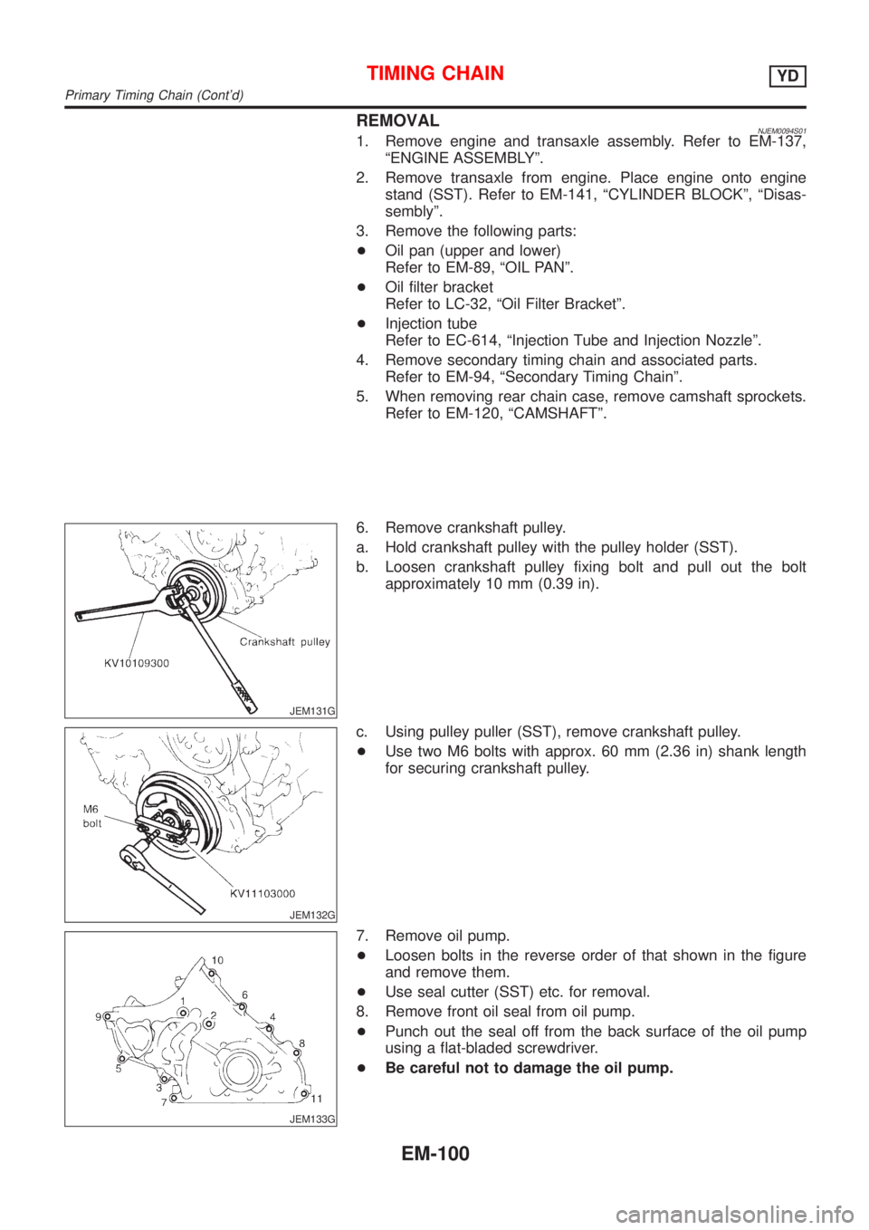
6. Remove crankshaft pulley.
a. Hold crankshaft pulley with the pulley holder (SST).
b. Loosen crankshaft pulley fixing bolt and pull out the bolt
approximately 10 mm (0.39 in).
JEM132G
c. Using pulley puller (SST), remove crankshaft pulley.
+Use two M6 bolts with approx. 60 mm (2.36 in) shank length
for securing crankshaft pulley.
JEM133G
7. Remove oil pump.
+Loosen bolts in the reverse order of that shown in the figure
and remove them.
+Use seal cutter (SST) etc. for removal.
8. Remove front oil seal from oil pump.
+Punch out the seal off from the back surface of the oil pump
using a flat-bladed screwdriver.
+Be careful not to damage the oil pump.
TIMING CHAINYD
Primary Timing Chain (Cont'd)
EM-100
Page 2354 of 2898
+Do not use gasoline, kerosine, diesel fuel, gas oil, thinners or
solvents for cleaning skin.
+If skin disorders develop, obtain medical advice without delay.
+Where practicable, degrease components prior to handling.
+Where there is a risk of eye contact, eye protection should be
worn, for example, chemical goggles or face shields; in addi-
tion an eye wash facility should be provided.
Environmental Protection PrecautionsNJGI0001S0702Burning used engine oil in small space heaters or boilers can be
recommended only for units of approved design. The heating sys-
tem must meet the requirements of HM Inspectorate of Pollution for
small burners of less than 0.4 MW. If in doubt, check with the
appropriate local authority and/or manufacturer of the approved
appliance.
Dispose of used oil and used oil filters through authorized waste
disposal contractors to licensed waste disposal sites, or to the
waste oil reclamation trade. If in doubt, contact the local authority
for advice on disposal facilities.
It is illegal to pour used oil on to the ground, down sewers or drains,
or into water courses.
The regulations concerning the pollution vary between
regions.
PRECAUTIONS FOR FUELNJGI0001S08Gasoline EngineNJGI0001S0803Models with three way catalyst
Unleaded premium gasoline of at least 95 octane (RON)
If premium gasoline is not available, unleaded regular gaso-
line with an octane rating of 91 (RON) may be temporarily
used, but only under the following precautions:
+Have the fuel tank filled only partially with unleaded regu-
lar gasoline, and fill up with premium unleaded gasoline
as soon as possible.
+Avoid full throttle driving and abrupt acceleration.
CAUTION:
Do not use leaded gasoline. Using leaded gasoline will dam-
age the three way catalyst.
Diesel Engine*:NJGI0001S0804Diesel fuel of at least 50 cetane
* If two types of diesel fuel are available, use summer or winter
fuel properly according to the following temperature conditions.
+Above þ7ÉC (20ÉF) ... Summer type diesel fuel.
+Below þ7ÉC (20ÉF) ... Winter type diesel fuel.
CAUTION:
+Do not use home heating oil, gasoline, or other alternate
fuels in your diesel engine. The use of those can cause
engine damage.
+Do not use summer fuel at temperatures below þ7ÉC
(20ÉF). The cold temperatures will cause wax to form in the
fuel. As a result, it may prevent the engine from running
smoothly.
+Do not add gasoline or other alternate fuels to diesel fuel.
PRECAUTIONS FOR AIR CONDITIONINGNJGI0001S09Use an approved refrigerant recovery unit any time the air condi-
tioning system must be discharged. Refer to HA-78, ªHFC-134a
(R-134a) Service Procedureº for specific instructions.
PRECAUTIONS
Precautions (Cont'd)
GI-8
Page 2507 of 2898
ENGINE LUBRICATION &
COOLING SYSTEMS
SECTION
LC
CONTENTS
QG
ENGINE LUBRICATION SYSTEM..................................3
Precautions ..................................................................3
LIQUID GASKET APPLICATION PROCEDURE............3
Preparation ..................................................................3
SPECIAL SERVICE TOOLS........................................3
Lubrication Circuit ........................................................4
Oil Pressure Check......................................................5
Oil Pump ......................................................................5
REMOVAL AND INSTALLATION.................................5
DISASSEMBLY AND ASSEMBLY................................6
INSPECTION.............................................................7
REGULATOR VALVE INSPECTION............................8
Changing Engine Oil....................................................8
Changing Oil Filter .......................................................9
Service Data and Specifications (SDS).....................10
OIL PRESSURE CHECK..........................................10
OIL PUMP INSPECTION..........................................10
REGULATOR VALVE INSPECTION..........................10
OIL CAPACITY........................................................10
ENGINE COOLING SYSTEM........................................ 11
Precautions ................................................................ 11
LIQUID GASKET APPLICATION PROCEDURE.......... 11
Preparation ................................................................ 11
SPECIAL SERVICE TOOLS...................................... 11
Cooling Circuit ...........................................................12
System Check............................................................12
CHECKING COOLING SYSTEM HOSES...................12
CHECKING RADIATOR............................................13
CHECKING RADIATOR CAP....................................13
CHECKING COOLING SYSTEM FOR LEAKS............13
Water Pump ...............................................................14
REMOVAL AND INSTALLATION...............................14
INSPECTION...........................................................14
Thermostat .................................................................15
REMOVAL AND INSTALLATION...............................15
INSPECTION...........................................................16
Radiator .....................................................................16
COMPONENTS.......................................................16
Cooling Fan ...............................................................17
COMPONENTS.......................................................17
CONTROL SYSTEM................................................18
Changing Engine Coolant..........................................18
- DRAINING ENGINE COOLANT -............................18
- REFILLING ENGINE COOLANT -...........................19
- FLUSHING COOLING SYSTEM -............................20
Radiator (Aluminum type) ..........................................21
PREPARATION.......................................................21
DISASSEMBLY........................................................21
ASSEMBLY.............................................................22
INSPECTION...........................................................23
Overheating Cause Analysis .....................................24
Service Data and Specifications (SDS).....................25
THERMOSTAT........................................................25
RADIATOR..............................................................25
COOLANT CAPACITY..............................................25
YD
ENGINE LUBRICATION SYSTEM................................26
Precautions ................................................................26
LIQUID GASKET APPLICATION PROCEDURE..........26
Preparation ................................................................26
SPECIAL SERVICE TOOLS......................................26
Lubrication Circuit ......................................................27
Oil Pressure Check....................................................28
Oil Pump ....................................................................28
REMOVAL AND INSTALLATION...............................28
DISASSEMBLY AND ASSEMBLY..............................29
OIL PUMP INSPECTION..........................................29
REGULATOR VALVE INSPECTION..........................30
Changing Engine Oil..................................................31
Oil Filter Bracket ........................................................32
REMOVAL AND INSTALLATION...............................32
Changing Oil Filter .....................................................32
REMOVAL...............................................................33
INSTALLATION........................................................33
Oil Cooler ...................................................................34
REMOVAL AND INSTALLATION...............................34
Service Data and Specifications (SDS).....................35
OIL PRESSURE CHECK..........................................35
Page 2509 of 2898
SEM164F
AEM080
Precautions
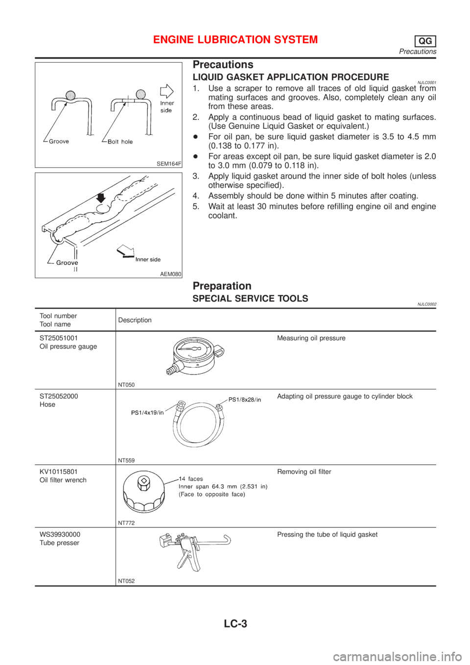
LIQUID GASKET APPLICATION PROCEDURENJLC00011. Use a scraper to remove all traces of old liquid gasket from
mating surfaces and grooves. Also, completely clean any oil
from these areas.
2. Apply a continuous bead of liquid gasket to mating surfaces.
(Use Genuine Liquid Gasket or equivalent.)
+For oil pan, be sure liquid gasket diameter is 3.5 to 4.5 mm
(0.138 to 0.177 in).
+For areas except oil pan, be sure liquid gasket diameter is 2.0
to 3.0 mm (0.079 to 0.118 in).
3. Apply liquid gasket around the inner side of bolt holes (unless
otherwise specified).
4. Assembly should be done within 5 minutes after coating.
5. Wait at least 30 minutes before refilling engine oil and engine
coolant.
Preparation
SPECIAL SERVICE TOOLSNJLC0002
Tool number
Tool nameDescription
ST25051001
Oil pressure gauge
NT050
Measuring oil pressure
ST25052000
Hose
NT559
Adapting oil pressure gauge to cylinder block
KV10115801
Oil filter wrench
NT772
Removing oil filter
WS39930000
Tube presser
NT052
Pressing the tube of liquid gasket
ENGINE LUBRICATION SYSTEMQG
Precautions
LC-3
Page 2514 of 2898
SLC986AA
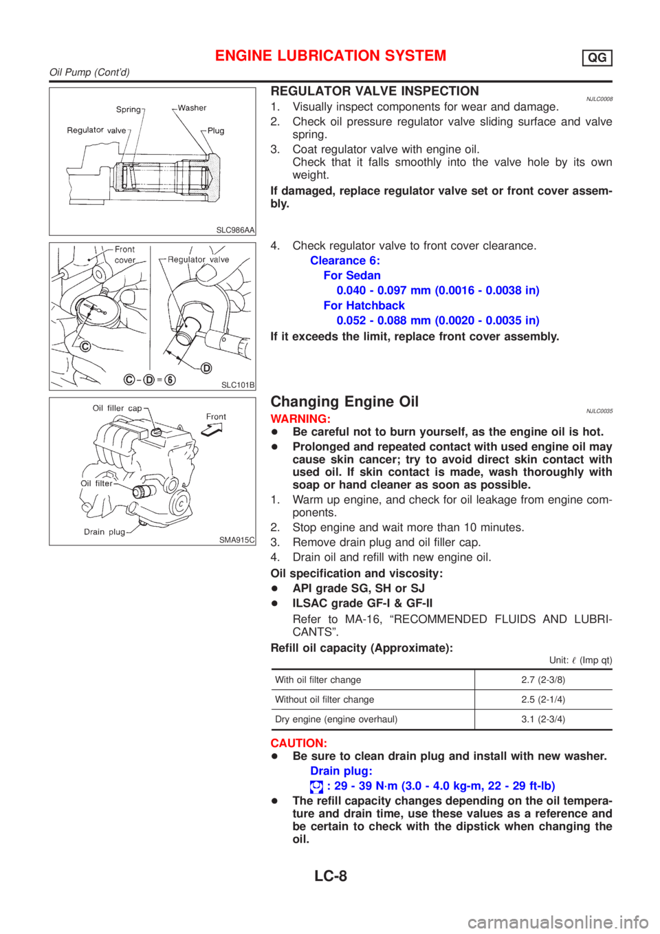
REGULATOR VALVE INSPECTIONNJLC00081. Visually inspect components for wear and damage.
2. Check oil pressure regulator valve sliding surface and valve
spring.
3. Coat regulator valve with engine oil.
Check that it falls smoothly into the valve hole by its own
weight.
If damaged, replace regulator valve set or front cover assem-
bly.
SLC101B
4. Check regulator valve to front cover clearance.
Clearance 6:
For Sedan
0.040 - 0.097 mm (0.0016 - 0.0038 in)
For Hatchback
0.052 - 0.088 mm (0.0020 - 0.0035 in)
If it exceeds the limit, replace front cover assembly.
SMA915C
Changing Engine OilNJLC0035WARNING:
+Be careful not to burn yourself, as the engine oil is hot.
+Prolonged and repeated contact with used engine oil may
cause skin cancer; try to avoid direct skin contact with
used oil. If skin contact is made, wash thoroughly with
soap or hand cleaner as soon as possible.
1. Warm up engine, and check for oil leakage from engine com-
ponents.
2. Stop engine and wait more than 10 minutes.
3. Remove drain plug and oil filler cap.
4. Drain oil and refill with new engine oil.
Oil specification and viscosity:
+API grade SG, SH or SJ
+ILSAC grade GF-I & GF-II
Refer to MA-16, ªRECOMMENDED FLUIDS AND LUBRI-
CANTSº.
Refill oil capacity (Approximate):
Unit:!(Imp qt)
With oil filter change 2.7 (2-3/8)
Without oil filter change 2.5 (2-1/4)
Dry engine (engine overhaul) 3.1 (2-3/4)
CAUTION:
+Be sure to clean drain plug and install with new washer.
Drain plug:
: 29 - 39 N´m (3.0 - 4.0 kg-m, 22 - 29 ft-lb)
+The refill capacity changes depending on the oil tempera-
ture and drain time, use these values as a reference and
be certain to check with the dipstick when changing the
oil.
ENGINE LUBRICATION SYSTEMQG
Oil Pump (Cont'd)
LC-8
Page 2515 of 2898
SMA390C
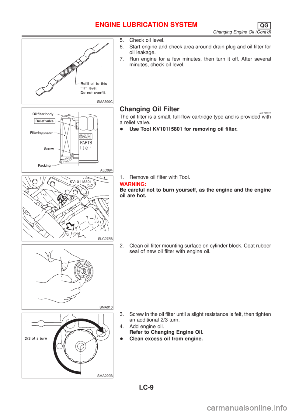
5. Check oil level.
6. Start engine and check area around drain plug and oil filter for
oil leakage.
7. Run engine for a few minutes, then turn it off. After several
minutes, check oil level.
ALC094
Changing Oil FilterNJLC0010The oil filter is a small, full-flow cartridge type and is provided with
a relief valve.
+Use Tool KV10115801 for removing oil filter.
SLC275B
1. Remove oil filter with Tool.
WARNING:
Be careful not to burn yourself, as the engine and the engine
oil are hot.
SMA010
2. Clean oil filter mounting surface on cylinder block. Coat rubber
seal of new oil filter with engine oil.
SMA229B
3. Screw in the oil filter until a slight resistance is felt, then tighten
an additional 2/3 turn.
4. Add engine oil.
Refer to Changing Engine Oil.
+Clean excess oil from engine.
ENGINE LUBRICATION SYSTEMQG
Changing Engine Oil (Cont'd)
LC-9
Page 2516 of 2898
Service Data and Specifications (SDS)
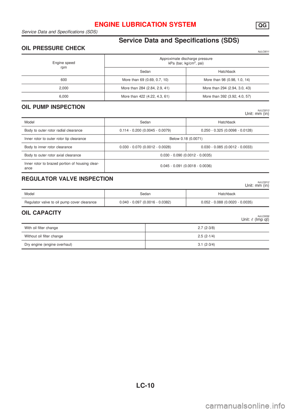
OIL PRESSURE CHECKNJLC0011
Engine speed
rpmApproximate discharge pressure
kPa (bar, kg/cm2, psi)
Sedan Hatchback
600 More than 69 (0.69, 0.7, 10) More than 98 (0.98, 1.0, 14)
2,000 More than 284 (2.84, 2.9, 41) More than 294 (2.94, 3.0, 43)
6,000 More than 422 (4.22, 4.3, 61) More than 392 (3.92, 4.0, 57)
OIL PUMP INSPECTIONNJLC0013Unit: mm (in)
Model Sedan Hatchback
Body to outer rotor radial clearance 0.114 - 0.200 (0.0045 - 0.0079) 0.250 - 0.325 (0.0098 - 0.0128)
Inner rotor to outer rotor tip clearance Below 0.18 (0.0071)
Body to inner rotor clearance 0.030 - 0.070 (0.0012 - 0.0028) 0.030 - 0.085 (0.0012 - 0.0033)
Body to outer rotor axial clearance 0.030 - 0.090 (0.0012 - 0.0035)
Inner rotor to brazed portion of housing clear-
ance0.045 - 0.091 (0.0018 - 0.0036)
REGULATOR VALVE INSPECTIONNJLC0012Unit: mm (in)
Model Sedan Hatchback
Regulator valve to oil pump cover clearance 0.040 - 0.097 (0.0016 - 0.0382) 0.052 - 0.088 (0.0020 - 0.0035)
OIL CAPACITYNJLC0036Unit:!(Imp qt)
With oil filter change2.7 (2-3/8)
Without oil filter change2.5 (2-1/4)
Dry engine (engine overhaul)3.1 (2-3/4)
ENGINE LUBRICATION SYSTEMQG
Service Data and Specifications (SDS)
LC-10
Page 2537 of 2898
SLC287B
JLC288B
Changing Engine OilNJLC0074WARNING:
+Be careful not to burn yourself, as the engine oil is hot.
+Prolonged and repeated contact with used engine oil may
cause skin cancer; try to avoid direct skin contact with
used oil. If skin contact is made, wash thoroughly with
soap or hand cleaner as soon as possible.
1. Warm up engine, and check for oil leakage from engine com-
ponents.
2. Stop engine and wait more than 10 minutes.
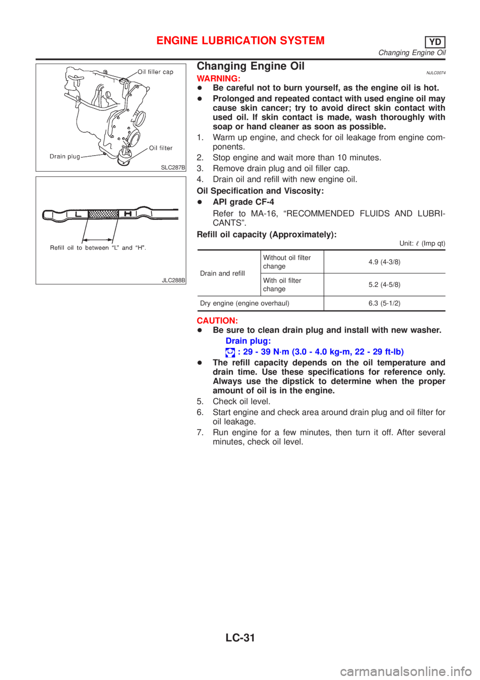
3. Remove drain plug and oil filler cap.
4. Drain oil and refill with new engine oil.
Oil Specification and Viscosity:
+API grade CF-4
Refer to MA-16, ªRECOMMENDED FLUIDS AND LUBRI-
CANTSº.
Refill oil capacity (Approximately):
Unit:!(Imp qt)
Drain and refillWithout oil filter
change4.9 (4-3/8)
With oil filter
change5.2 (4-5/8)
Dry engine (engine overhaul) 6.3 (5-1/2)
CAUTION:
+Be sure to clean drain plug and install with new washer.
Drain plug:
: 29 - 39 N´m (3.0 - 4.0 kg-m, 22 - 29 ft-lb)
+The refill capacity depends on the oil temperature and
drain time. Use these specifications for reference only.
Always use the dipstick to determine when the proper
amount of oil is in the engine.
5. Check oil level.
6. Start engine and check area around drain plug and oil filter for
oil leakage.
7. Run engine for a few minutes, then turn it off. After several
minutes, check oil level.
ENGINE LUBRICATION SYSTEMYD
Changing Engine Oil
LC-31
Page 2538 of 2898
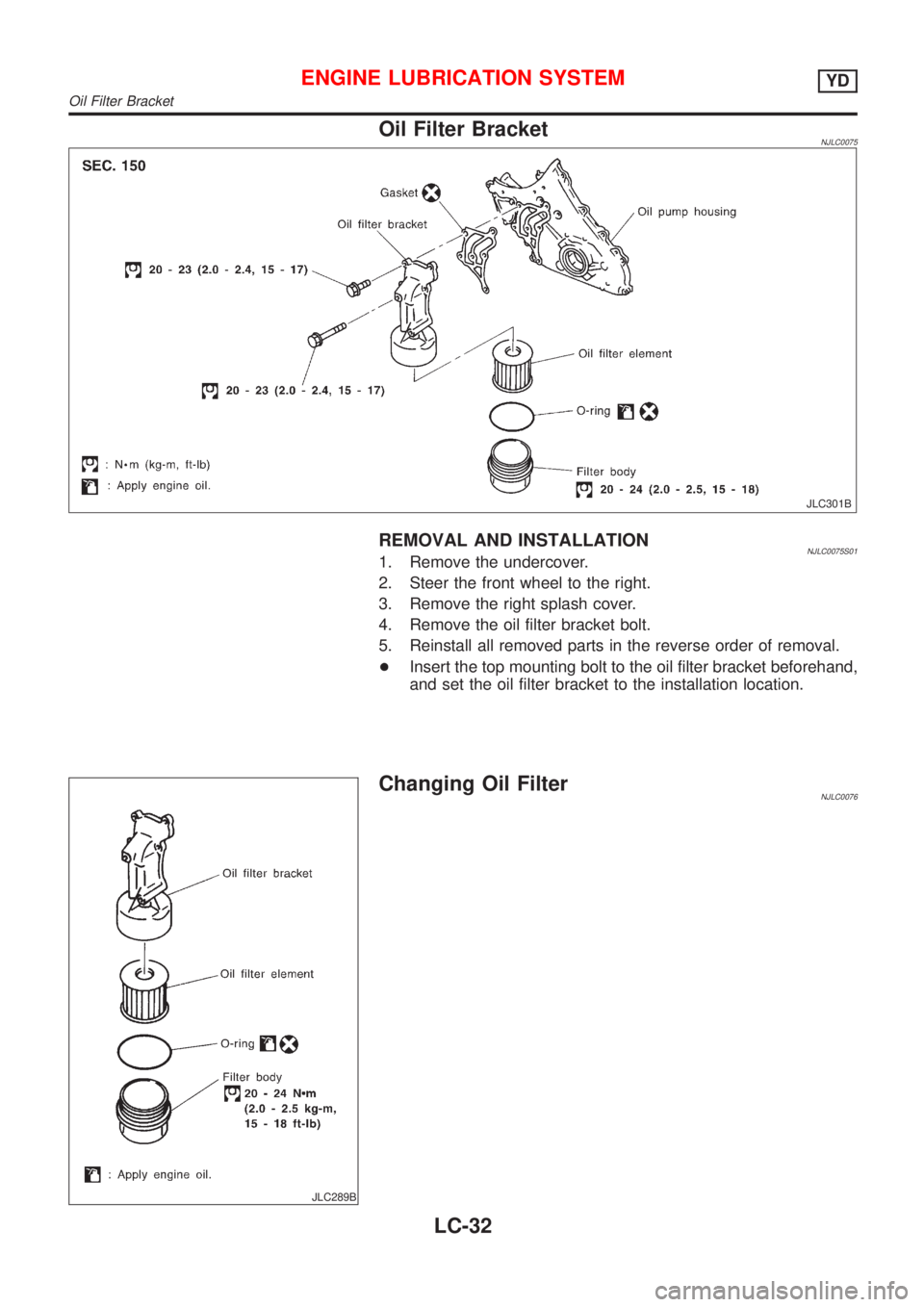
Oil Filter BracketNJLC0075
JLC301B
REMOVAL AND INSTALLATIONNJLC0075S011. Remove the undercover.
2. Steer the front wheel to the right.
3. Remove the right splash cover.
4. Remove the oil filter bracket bolt.
5. Reinstall all removed parts in the reverse order of removal.
+Insert the top mounting bolt to the oil filter bracket beforehand,
and set the oil filter bracket to the installation location.
JLC289B
Changing Oil FilterNJLC0076
ENGINE LUBRICATION SYSTEMYD
Oil Filter Bracket
LC-32