oil type NISSAN ALMERA 2001 Owner's Manual
[x] Cancel search | Manufacturer: NISSAN, Model Year: 2001, Model line: ALMERA, Model: NISSAN ALMERA 2001Pages: 2898, PDF Size: 60.76 MB
Page 2405 of 2898
+When installing an air conditioner in the vehicle, connect the pipes as the final stage of the opera-
tion. Do not remove the seal caps of pipes and other components until just before required for
connection.
+Allow components stored in cool areas to warm to working area temperature before removing seal
caps. This prevents condensation from forming inside A/C components.
+Thoroughly remove moisture from the refrigeration system before charging the refrigerant.
+Always replace used O-rings.
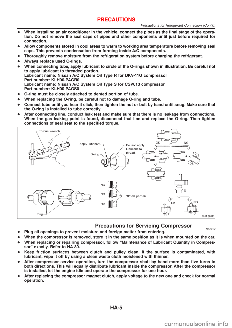
+When connecting tube, apply lubricant to circle of the O-rings shown in illustration. Be careful not
to apply lubricant to threaded portion.
Lubricant name: Nissan A/C System Oil Type R for DKV-11G compressor
Part number: KLH00-PAGR0
Lubricant name: Nissan A/C System Oil Type S for CSV613 compressor
Part number: KLH00-PAGS0
+O-ring must be closely attached to dented portion of tube.
+When replacing the O-ring, be careful not to damage O-ring and tube.
+Connect tube until you hear it click, then tighten the nut or bolt by hand until snug. Make sure that
the O-ring is installed to tube correctly.
+After connecting line, conduct leak test and make sure that there is no leakage from connections.
When the gas leaking point is found, disconnect that line and replace the O-ring. Then tighten
connections of seal seat to the specified torque.
RHA861F
Precautions for Servicing CompressorNJHA0116+Plug all openings to prevent moisture and foreign matter from entering.
+When the compressor is removed, store it in the same position as it is when mounted on the car.
+When replacing or repairing compressor, follow ªMaintenance of Lubricant Quantity in Compres-
sorº exactly. Refer to HA-80.
+Keep friction surfaces between clutch and pulley clean. If the surface is contaminated, with
lubricant, wipe it off by using a clean waste cloth moistened with thinner.
+After compressor service operation, turn the compressor shaft by hand more than five turns in
both directions. This will equally distribute lubricant inside the compressor. After the compressor
is installed, let the engine idle and operate the compressor for one hour.
+After replacing the compressor magnet clutch, apply voltage to the new one and check for normal
operation.
PRECAUTIONS
Precautions for Refrigerant Connection (Cont'd)
HA-5
Page 2411 of 2898
HFC-134a (R-134a) Service Tools and
Equipment
=NJHA0120Never mix HFC-134a refrigerant and/or its specified lubricant with CFC-12 (R-12) refrigerant and/or its lubri-
cant.
Separate and non-interchangeable service equipment must be used for handling each type of refrigerant/
lubricant.
Refrigerant container fittings, service hose fittings and service equipment fittings (equipment which handles
refrigerant and/or lubricant) are different between CFC-12 (R-12) and HFC-134a (R-134a). This is to avoid
mixed use of the refrigerants/lubricant.
Adapters that convert one size fitting to another must never be used: refrigerant/lubricant contamination will
occur and compressor failure will result.
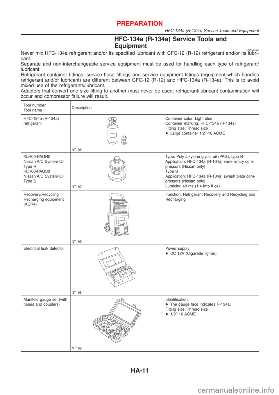
Tool number
Tool nameDescription
HFC-134a (R-134a)
refrigerant
NT196
Container color: Light blue
Container marking: HFC-134a (R-134a)
Fitting size: Thread size
+Large container 1/2²-16 ACME
KLH00-PAGR0
Nissan A/C System Oil
Type R
KLH00-PAGS0
Nissan A/C System Oil
Type S
NT197
Type: Poly alkylene glycol oil (PAG), type R
Application: HFC-134a (R-134a) vane rotary com-
pressors (Nissan only)
Type S
Application: HFC-134a (R-134a) swash plate com-
pressors (Nissan only)
Lubricity: 40 m!(1.4 Imp fl oz)
Recovery/Recycling
Recharging equipment
(ACR4)
NT195
Function: Refrigerant Recovery and Recycling and
Recharging
Electrical leak detector
NT198
Power supply:
+DC 12V (Cigarette lighter)
Manifold gauge set (with
hoses and couplers)
NT199
Identification:
+The gauge face indicates R-134a.
Fitting size: Thread size
+1/2²-16 ACME
PREPARATION
HFC-134a (R-134a) Service Tools and Equipment
HA-11
Page 2480 of 2898
Maintenance of Lubricant Quantity in
Compressor
NJHA0160The lubricant in the compressor circulates through the system with
the refrigerant. Add lubricant to compressor when replacing any
component or after a large gas leakage occurred. It is important to
maintain the specified amount.
If lubricant quantity is not maintained properly, the following mal-
functions may result:
+Lack of lubricant: May lead to a seized compressor
+Excessive lubricant: Inadequate cooling (thermal exchange
interference)
LUBRICANTNJHA0160S01Name: Nissan A/C System Oil Type R for DKV-11G compres-
sor
Part number: KLH00-PAGR0
Name: Nissan A/C System Oil Type S for CSV613 compressor
Part number: KLH00-PAGS0
CHECKING AND ADJUSTINGNJHA0160S02Adjust the lubricant quantity according to the test group shown
below.
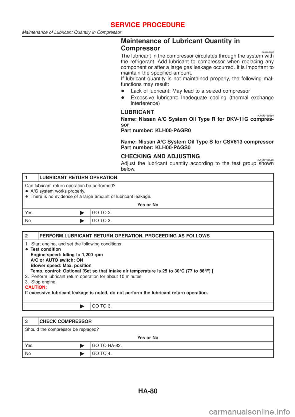
1 LUBRICANT RETURN OPERATION
Can lubricant return operation be performed?
+A/C system works properly.
+There is no evidence of a large amount of lubricant leakage.
YesorNo
Ye s©GO TO 2.
No©GO TO 3.
2 PERFORM LUBRICANT RETURN OPERATION, PROCEEDING AS FOLLOWS
1. Start engine, and set the following conditions:
+Test condition
Engine speed: Idling to 1,200 rpm
A/C or AUTO switch: ON
Blower speed: Max. position
Temp. control: Optional [Set so that intake air temperature is 25 to 30ÉC (77 to 86ÉF).]
2. Perform lubricant return operation for about 10 minutes.
3. Stop engine.
CAUTION:
If excessive lubricant leakage is noted, do not perform the lubricant return operation.
©GO TO 3.
3 CHECK COMPRESSOR
Should the compressor be replaced?
YesorNo
Ye s©GO TO HA-82.
No©GO TO 4.
SERVICE PROCEDURE
Maintenance of Lubricant Quantity in Compressor
HA-80
Page 2497 of 2898
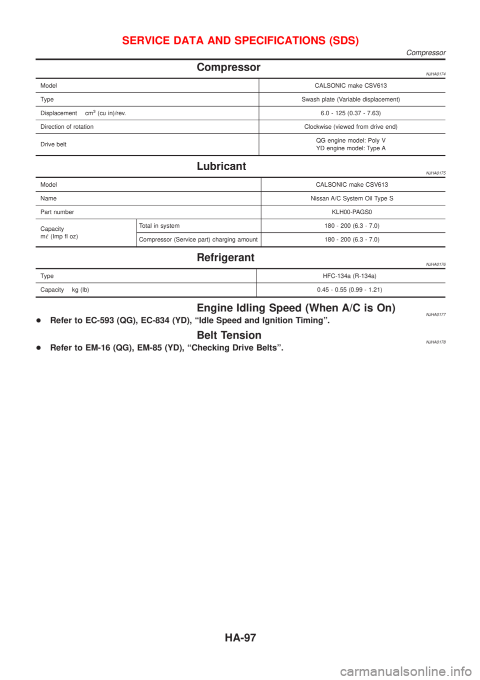
CompressorNJHA0174
ModelCALSONIC make CSV613
TypeSwash plate (Variable displacement)
Displacement cm
3(cu in)/rev.6.0 - 125 (0.37 - 7.63)
Direction of rotationClockwise (viewed from drive end)
Drive beltQG engine model: Poly V
YD engine model: Type A
LubricantNJHA0175
ModelCALSONIC make CSV613
NameNissan A/C System Oil Type S
Part numberKLH00-PAGS0
Capacity
m!(Imp fl oz)Total in system 180 - 200 (6.3 - 7.0)
Compressor (Service part) charging amount 180 - 200 (6.3 - 7.0)
RefrigerantNJHA0176
TypeHFC-134a (R-134a)
Capacity kg (lb)0.45 - 0.55 (0.99 - 1.21)
Engine Idling Speed (When A/C is On)NJHA0177+Refer to EC-593 (QG), EC-834 (YD), ªIdle Speed and Ignition Timingº.
Belt TensionNJHA0178+Refer to EM-16 (QG), EM-85 (YD), ªChecking Drive Beltsº.
SERVICE DATA AND SPECIFICATIONS (SDS)
Compressor
HA-97
Page 2504 of 2898
NVH troubleshooting (SU) ........................ SU-16
NVH troubleshooting (CL) ........................... CL-4
NVIS (Nissan vehicle immobiliser sys-
tem) precautions ....................................... GI-3
Neutral position switch .................... EC-437, 536
O
Oil pan (engine) .................................. EM-20, 89
Oil pressure (engine) ............................ LC-5, 28
Oil pump (A/T) ......................................... AT-384
Oil pump (engine) ................................. LC-5, 28
Oil pump regulator valve (engine) ......... LC-8, 30
Oil seal replacement (engine) .................. EM-32
On board diagnostic system ............. EC-59, 627
Operating cylinder (clutch) ........................ CL-14
Overdrive control switch .......................... AT-341
Overrun clutch .......................................... AT-412
P
P/ANT - Wiring diagram .......................... EL-282
PCV (positive crankcase
ventilation) ..................................... EC-39, 613
PGC/V - Wiring diagram ................. EC-366, 505
PNP/SW - Wiring diagram ...... EC-439, 537, 826
POWER - Wiring diagram ................... EL-11, 28
PST/SW - Wiring diagram ....................... EC-568
Park/Neutral position switch ... EC-437, 536, 826
Park/neutral position switch (A/T) ............ AT-183
Park/neutral position switch (M/T) ............ MT-21
Parking brake control ................................ BR-47
Parking lamp .............................................. EL-81
Piston assembly ............................... EM-62, 155
Piston pin inspection ........................ EM-56, 145
Piston ring inspection ....................... EM-56, 145
Piston to bore clearance .................. EM-58, 147
Power antenna ........................................ EL-282
Power door lock ....................................... EL-314
Power door mirror .................................... EL-294
Power steering fluid level ............................ ST-7
Power steering gear .................................. ST-16
Power steering hydraulic pressure .............. ST-9
Power steering oil pressure switch ......... EC-567
Power steering oil pump ............................ ST-25
Power steering system bleeding ................. ST-8
Power supply routing ................................. EL-10
Power window ......................................... EL-298
Precautions (General) .................................. GI-4
Pressure plate - See Clutch cover ............ CL-22
Priming pump .................................. EC-625, 641
Q
Quick-glow system .................................. EC-806
R
RR02 - Wiring diagram .......... EC-261, 270, 278,
286, 463
RR02/H - Wiring diagram ............... EC-293, 470
Radiator ............................................... LC-16, 42
Radio - See Audio ................................... EL-258
Rear air spoiler .......................................... BT-47
Rear axle (disc brake type) ....................... AX-24
Rear axle ................................................... AX-22
Rear bumper .............................................. BT-10
Rear combination lamp removal and
installation .............................................. BT-47
Rear disc brake .................................. BR-35, 43
Rear door ................................................... BT-16
Rear drum brake ....................................... BR-31
Rear heated oxygen sensor (HO2S)
heater .......................................... EC-291, 469
Rear heated oxygen sensor (HO2S) ..... EC-258,
267, 275, 284, 462
Rear seat belt ............................................ RS-11
Rear seat ................................................... BT-60
Rear suspension ....................................... SU-16
Rear window defogger ............................ EL-240
Rear window .............................................. BT-71
Refrigerant connection precaution .............. HA-3
Refrigerant general precaution ................... HA-2
Refrigerant lines ........................................ HA-91
Refrigeration cycle .................................... HA-13
Release bearing (clutch) ..................... CL-17, 20
Removal and installation (A/T) ................ AT-354
Reverse clutch ......................................... AT-403
Reverse idler shaft (M/T) .............. MT-30, 54, 93
Reverse lamp switch (M/T) - See
Back-up lamp switch (M/T) ................... MT-21
Reverse main gear (M/T) ............. MT-31, 55, 93
Road wheel size ......................................... GI-43
Roof trim .................................................... BT-43
Room lamp - See Interior lamp ............... EL-115
S
S/LOCK - Wiring diagram ............... EL-318, 335,
352, 372
S/SIG - Wiring diagram ........................... EC-558
SAE J1930 terminology list ........................ GI-50
SHIFT - Wiring diagram ........................... AT-344
SROOF - Wiring diagram ........................ EL-292
SRS - See Supplemental Restraint
System ................................................... RS-20
START - Wiring diagram ........................... SC-14
STOP/L - Wiring diagram .................... EL-85, 86
SWL/V - Wiring diagram ................. EC-399, 475
Seal - See Exterior .................................... BT-47
Seat belt pre-tensioner disposal ............... RS-40
Seat belt pre-tensioner ............................... RS-3
Seat belt, front ............................................ RS-5
Seat belt, rear ............................................ RS-11
Seat, front .................................................. BT-56
ALPHABETICAL INDEX
IDX-6
Page 2507 of 2898
ENGINE LUBRICATION &
COOLING SYSTEMS
SECTION
LC
CONTENTS
QG
ENGINE LUBRICATION SYSTEM..................................3
Precautions ..................................................................3
LIQUID GASKET APPLICATION PROCEDURE............3
Preparation ..................................................................3
SPECIAL SERVICE TOOLS........................................3
Lubrication Circuit ........................................................4
Oil Pressure Check......................................................5
Oil Pump ......................................................................5
REMOVAL AND INSTALLATION.................................5
DISASSEMBLY AND ASSEMBLY................................6
INSPECTION.............................................................7
REGULATOR VALVE INSPECTION............................8
Changing Engine Oil....................................................8
Changing Oil Filter .......................................................9
Service Data and Specifications (SDS).....................10
OIL PRESSURE CHECK..........................................10
OIL PUMP INSPECTION..........................................10
REGULATOR VALVE INSPECTION..........................10
OIL CAPACITY........................................................10
ENGINE COOLING SYSTEM........................................ 11
Precautions ................................................................ 11
LIQUID GASKET APPLICATION PROCEDURE.......... 11
Preparation ................................................................ 11
SPECIAL SERVICE TOOLS...................................... 11
Cooling Circuit ...........................................................12
System Check............................................................12
CHECKING COOLING SYSTEM HOSES...................12
CHECKING RADIATOR............................................13
CHECKING RADIATOR CAP....................................13
CHECKING COOLING SYSTEM FOR LEAKS............13
Water Pump ...............................................................14
REMOVAL AND INSTALLATION...............................14
INSPECTION...........................................................14
Thermostat .................................................................15
REMOVAL AND INSTALLATION...............................15
INSPECTION...........................................................16
Radiator .....................................................................16
COMPONENTS.......................................................16
Cooling Fan ...............................................................17
COMPONENTS.......................................................17
CONTROL SYSTEM................................................18
Changing Engine Coolant..........................................18
- DRAINING ENGINE COOLANT -............................18
- REFILLING ENGINE COOLANT -...........................19
- FLUSHING COOLING SYSTEM -............................20
Radiator (Aluminum type) ..........................................21
PREPARATION.......................................................21
DISASSEMBLY........................................................21
ASSEMBLY.............................................................22
INSPECTION...........................................................23
Overheating Cause Analysis .....................................24
Service Data and Specifications (SDS).....................25
THERMOSTAT........................................................25
RADIATOR..............................................................25
COOLANT CAPACITY..............................................25
YD
ENGINE LUBRICATION SYSTEM................................26
Precautions ................................................................26
LIQUID GASKET APPLICATION PROCEDURE..........26
Preparation ................................................................26
SPECIAL SERVICE TOOLS......................................26
Lubrication Circuit ......................................................27
Oil Pressure Check....................................................28
Oil Pump ....................................................................28
REMOVAL AND INSTALLATION...............................28
DISASSEMBLY AND ASSEMBLY..............................29
OIL PUMP INSPECTION..........................................29
REGULATOR VALVE INSPECTION..........................30
Changing Engine Oil..................................................31
Oil Filter Bracket ........................................................32
REMOVAL AND INSTALLATION...............................32
Changing Oil Filter .....................................................32
REMOVAL...............................................................33
INSTALLATION........................................................33
Oil Cooler ...................................................................34
REMOVAL AND INSTALLATION...............................34
Service Data and Specifications (SDS).....................35
OIL PRESSURE CHECK..........................................35
Page 2508 of 2898

REGULATOR VALVE INSPECTION..........................35
OIL PUMP INSPECTION..........................................35
ENGINE OIL CAPACITY...........................................35
ENGINE COOLING SYSTEM........................................36
Precautions ................................................................36
LIQUID GASKET APPLICATION PROCEDURE..........36
Preparation ................................................................36
SPECIAL SERVICE TOOLS......................................36
Cooling Circuit ...........................................................37
System Check............................................................38
CHECKING COOLING SYSTEM HOSES...................38
CHECKING RADIATOR............................................38
CHECKING RADIATOR CAP....................................38
CHECKING COOLING SYSTEM FOR LEAKS............39
Water Pump ...............................................................39
REMOVAL AND INSTALLATION...............................39
REMOVAL...............................................................40
INSPECTION...........................................................40
INSTALLATION........................................................40
Thermostat .................................................................41
REMOVAL AND INSTALLATION...............................41
INSPECTION...........................................................42
Radiator .....................................................................42
COMPONENTS.......................................................42
REMOVAL AND INSTALLATION...............................43
Cooling Fan ...............................................................43
COMPONENTS.......................................................43
CONTROL SYSTEM................................................43
Changing Engine Coolant..........................................44
- DRAINING ENGINE COOLANT -............................44
- REFILLING ENGINE COOLANT -...........................45
- FLUSHING COOLING SYSTEM -............................46
Radiator (Aluminum type) ..........................................47
Overheating Cause Analysis .....................................47
Service Data and Specifications (SDS).....................48
THERMOSTAT........................................................48
RADIATOR..............................................................48
ENGINE COOLANT CAPACITY................................48
CONTENTS(Cont'd)
LC-2
Page 2515 of 2898
SMA390C
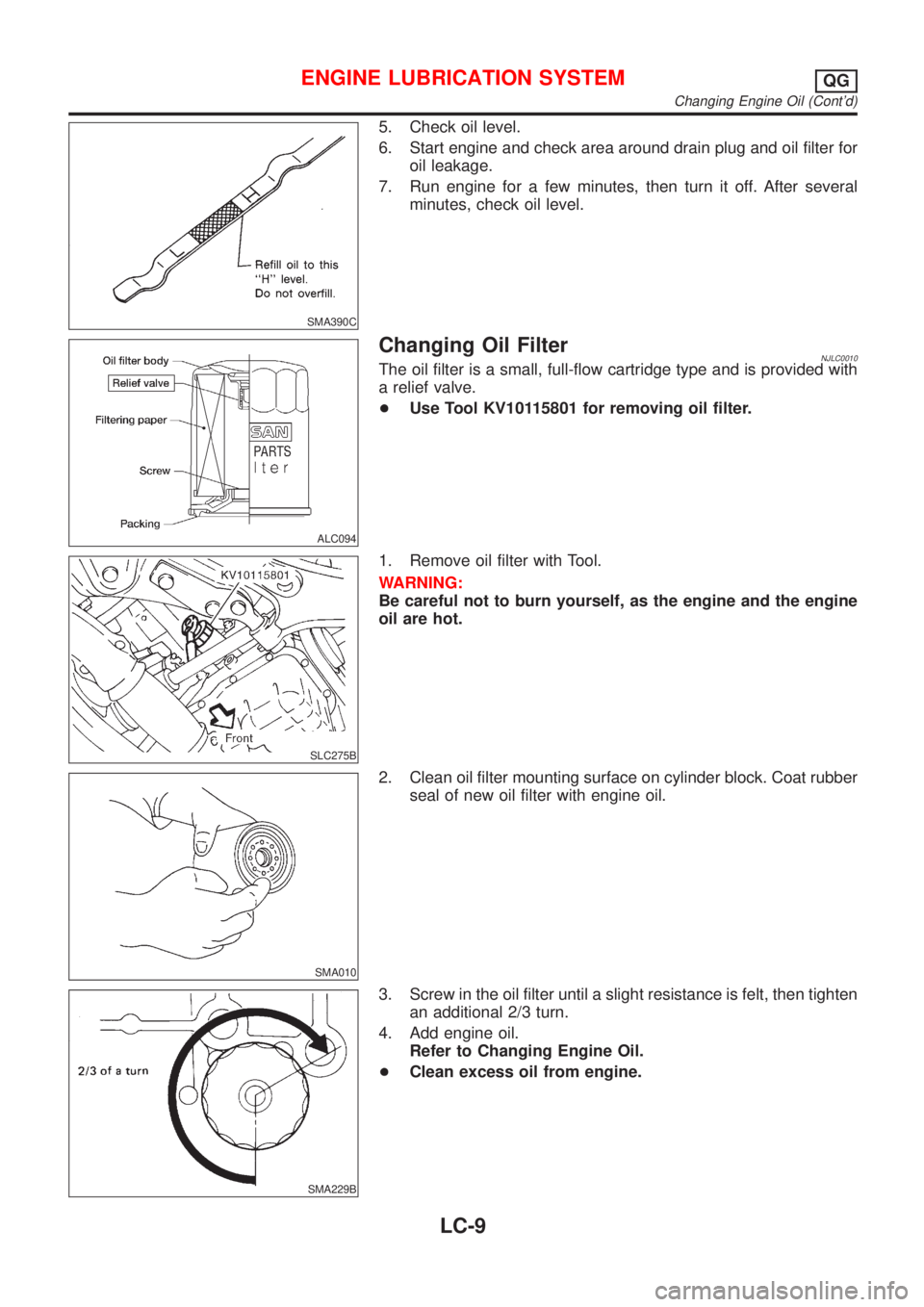
5. Check oil level.
6. Start engine and check area around drain plug and oil filter for
oil leakage.
7. Run engine for a few minutes, then turn it off. After several
minutes, check oil level.
ALC094
Changing Oil FilterNJLC0010The oil filter is a small, full-flow cartridge type and is provided with
a relief valve.
+Use Tool KV10115801 for removing oil filter.
SLC275B
1. Remove oil filter with Tool.
WARNING:
Be careful not to burn yourself, as the engine and the engine
oil are hot.
SMA010
2. Clean oil filter mounting surface on cylinder block. Coat rubber
seal of new oil filter with engine oil.
SMA229B
3. Screw in the oil filter until a slight resistance is felt, then tighten
an additional 2/3 turn.
4. Add engine oil.
Refer to Changing Engine Oil.
+Clean excess oil from engine.
ENGINE LUBRICATION SYSTEMQG
Changing Engine Oil (Cont'd)
LC-9
Page 2528 of 2898
SLC930
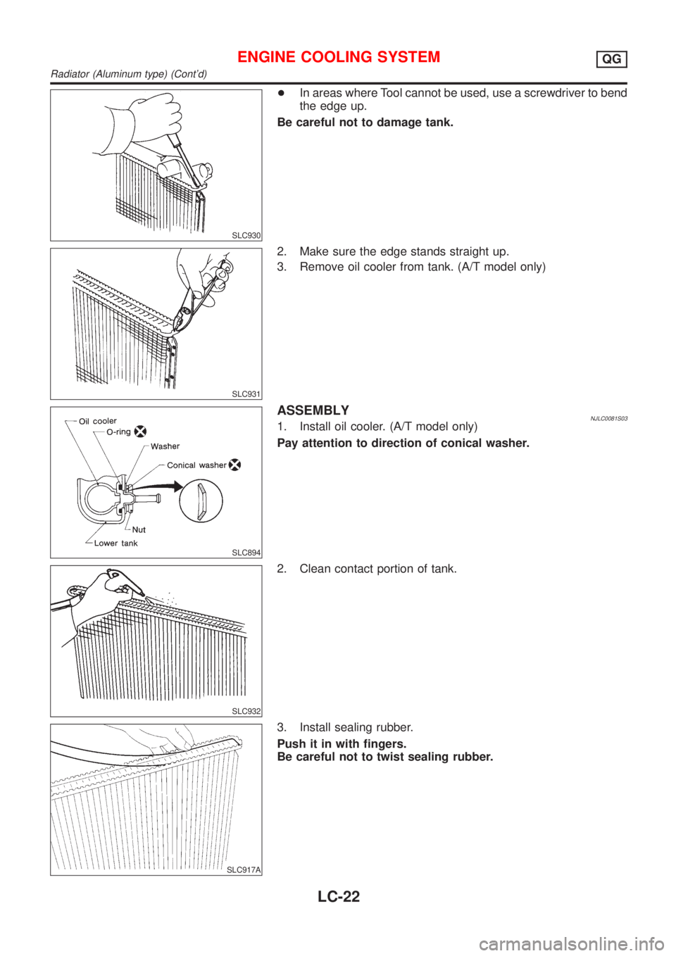
+In areas where Tool cannot be used, use a screwdriver to bend
the edge up.
Be careful not to damage tank.
SLC931
2. Make sure the edge stands straight up.
3. Remove oil cooler from tank. (A/T model only)
SLC894
ASSEMBLYNJLC0081S031. Install oil cooler. (A/T model only)
Pay attention to direction of conical washer.
SLC932
2. Clean contact portion of tank.
SLC917A
3. Install sealing rubber.
Push it in with fingers.
Be careful not to twist sealing rubber.
ENGINE COOLING SYSTEMQG
Radiator (Aluminum type) (Cont'd)
LC-22
Page 2529 of 2898
SLC904
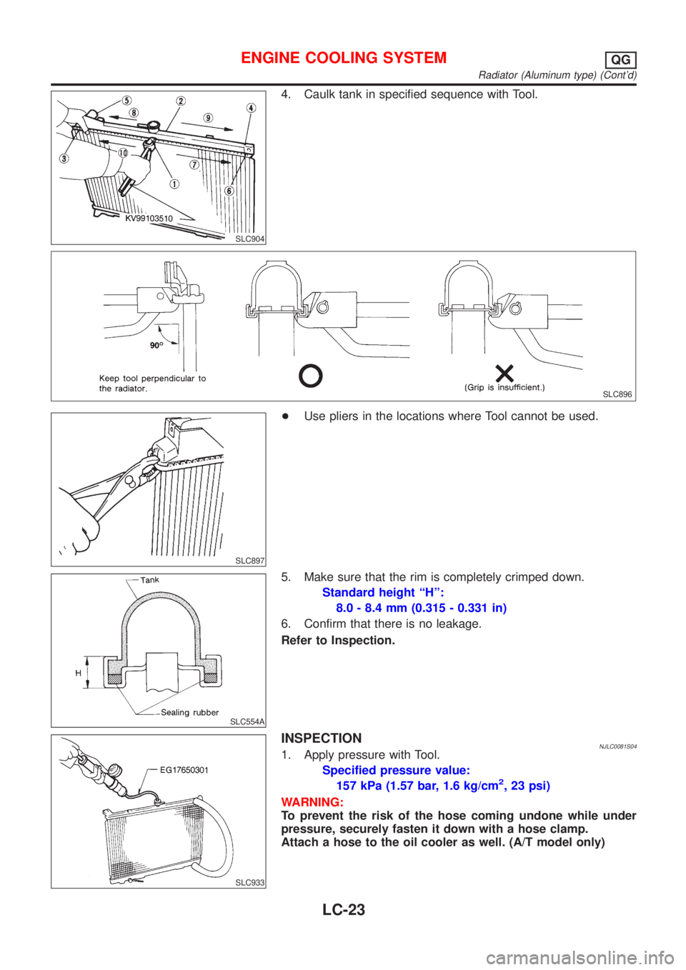
4. Caulk tank in specified sequence with Tool.
SLC896
SLC897
+Use pliers in the locations where Tool cannot be used.
SLC554A
5. Make sure that the rim is completely crimped down.
Standard height ªHº:
8.0 - 8.4 mm (0.315 - 0.331 in)
6. Confirm that there is no leakage.
Refer to Inspection.
SLC933
INSPECTIONNJLC0081S041. Apply pressure with Tool.
Specified pressure value:
157 kPa (1.57 bar, 1.6 kg/cm
2, 23 psi)
WARNING:
To prevent the risk of the hose coming undone while under
pressure, securely fasten it down with a hose clamp.
Attach a hose to the oil cooler as well. (A/T model only)
ENGINE COOLING SYSTEMQG
Radiator (Aluminum type) (Cont'd)
LC-23