water pump NISSAN ALMERA 2001 Owner's Manual
[x] Cancel search | Manufacturer: NISSAN, Model Year: 2001, Model line: ALMERA, Model: NISSAN ALMERA 2001Pages: 2898, PDF Size: 60.76 MB
Page 2276 of 2898
JEM193G
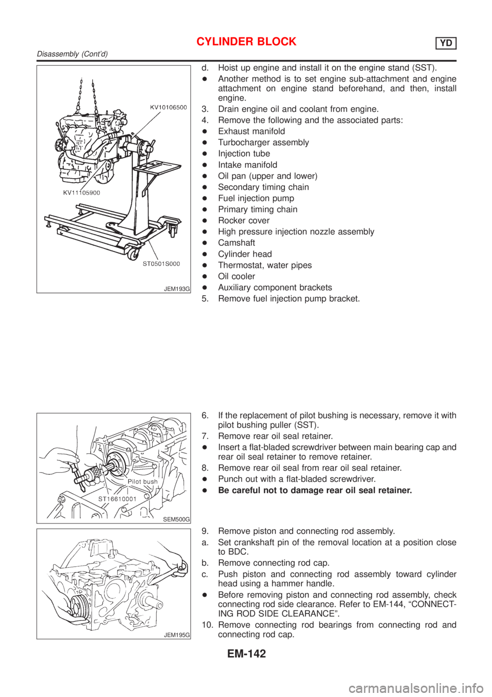
d. Hoist up engine and install it on the engine stand (SST).
+Another method is to set engine sub-attachment and engine
attachment on engine stand beforehand, and then, install
engine.
3. Drain engine oil and coolant from engine.
4. Remove the following and the associated parts:
+Exhaust manifold
+Turbocharger assembly
+Injection tube
+Intake manifold
+Oil pan (upper and lower)
+Secondary timing chain
+Fuel injection pump
+Primary timing chain
+Rocker cover
+High pressure injection nozzle assembly
+Camshaft
+Cylinder head
+Thermostat, water pipes
+Oil cooler
+Auxiliary component brackets
5. Remove fuel injection pump bracket.
SEM500G
6. If the replacement of pilot bushing is necessary, remove it with
pilot bushing puller (SST).
7. Remove rear oil seal retainer.
+Insert a flat-bladed screwdriver between main bearing cap and
rear oil seal retainer to remove retainer.
8. Remove rear oil seal from rear oil seal retainer.
+Punch out with a flat-bladed screwdriver.
+Be careful not to damage rear oil seal retainer.
JEM195G
9. Remove piston and connecting rod assembly.
a. Set crankshaft pin of the removal location at a position close
to BDC.
b. Remove connecting rod cap.
c. Push piston and connecting rod assembly toward cylinder
head using a hammer handle.
+Before removing piston and connecting rod assembly, check
connecting rod side clearance. Refer to EM-144, ªCONNECT-
ING ROD SIDE CLEARANCEº.
10. Remove connecting rod bearings from connecting rod and
connecting rod cap.
CYLINDER BLOCKYD
Disassembly (Cont'd)
EM-142
Page 2294 of 2898
General SpecificationsNJEM0075
Cylinder arrangementIn-line 4
Displacement cm
3(cu in)2,184 (133.27)
Bore and stroke mm (in)86 x 94 (3.39 x 3.70)
Valve arrangementDOHC
Firing order1-3-4-2
Number of piston ringsCompression 2
Oil 1
Number of main bearings5
Compression ratio18.0
Compression PressureNJEM0076Unit: kPa (bar, kg/cm2, psi)/200 rpm
Compression pressureStandard 3,138 (31.4, 32.0, 455)
Minimum 2,452 (24.5, 25.0, 356)
Differential limit between cylinders 490 (4.9, 5.0, 71)
Belt DeflectionNJEM0111
Applied belt Belt specificationBelt deflection with 98 N (10 kg, 22 lb) force applied*
mm (in)
New AdjustedLimit for re-tighten-
ing
Air conditioner compressor belt HA type low edge belt4-5
(0.16 - 0.20)6-7
(0.24 - 0.28)8.5 (0.335)
Alternator & water pump beltHA type low-edge wide angle
belt9.0 - 10.5
(0.354 - 0.413)11.0 - 12.5
(0.433 - 0.492)16.5 (0.650)
*: When engine is cold.
Cylinder HeadNJEM0077Unit: mm (in)
Standard Limit
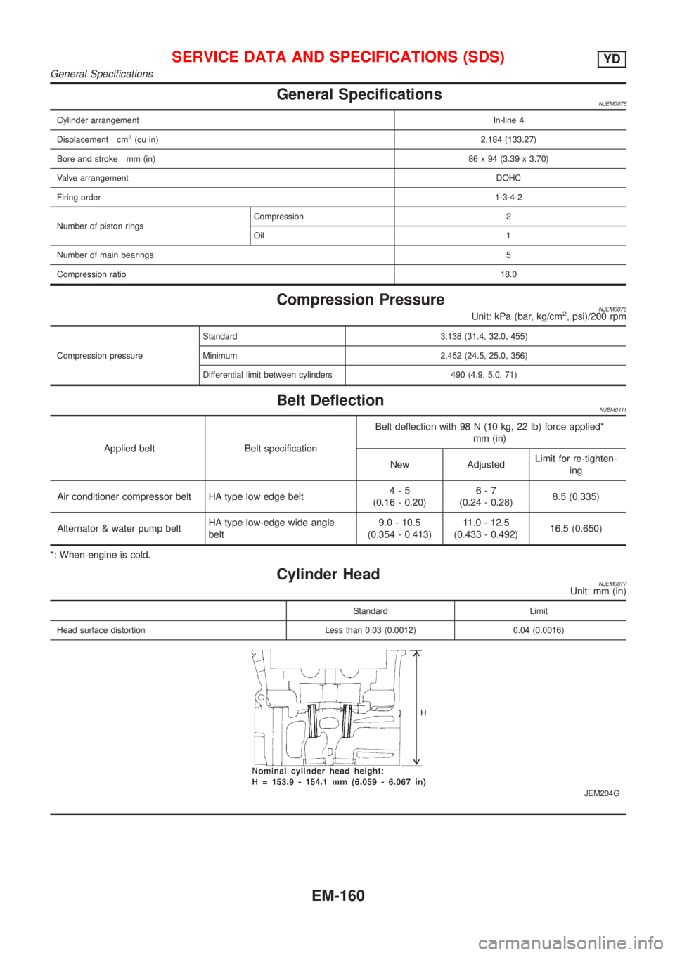
Head surface distortion Less than 0.03 (0.0012) 0.04 (0.0016)
JEM204G
SERVICE DATA AND SPECIFICATIONS (SDS)YD
General Specifications
EM-160
Page 2305 of 2898

ACCELERATOR CONTROL, FUEL &
EXHAUST SYSTEMS
SECTION
FE
CONTENTS
QG
PREPARATION...............................................................2
Special Service Tools ..................................................2
Commercial Service Tools ...........................................2
ACCELERATOR CONTROL SYSTEM...........................3
Removal and Installation .............................................3
Adjusting Accelerator Wire ..........................................3
MODELS WITH THROTTLE OPENER.........................3
MODELS WITHOUT THROTTLE OPENER..................4
FUEL SYSTEM................................................................5
Checking Fuel Lines ....................................................5
Removal and Installation .............................................5
Fuel Tank .....................................................................6
REMOVAL.................................................................7
INSTALLATION........................................................ 11
Fuel Pump, Fuel Level Sensor Unit and Fuel
Filter ...........................................................................12
REMOVAL...............................................................12
INSTALLATION........................................................14
EXHAUST SYSTEM......................................................15
Checking Exhaust System.........................................15
Removal and Installation ...........................................15
YD
PREPARATION.............................................................18
Special Service Tool ..................................................18Commercial Service Tool ...........................................18
ACCELERATOR CONTROL SYSTEM.........................19
Removal and Installation ...........................................19
Inspection...................................................................19
FUEL SYSTEM..............................................................20
Checking Fuel Lines ..................................................20
Water Draining from Fuel Filter .................................20
DRAINING WATER..................................................20
FUEL FILTER CHECK..............................................20
Changing Fuel Filter ..................................................20
REMOVAL...............................................................20
INSTALLATION........................................................21
Bleeding Fuel Filter....................................................21
Checking Priming Pump ............................................21
Checking Water in Fuel Filter Sensor (where
fitted) ..........................................................................22
Removal and Installation ...........................................22
Fuel Tank ...................................................................23
REMOVAL...............................................................25
INSTALLATION........................................................28
Fuel Level Sensor Unit ..............................................29
REMOVAL...............................................................30
INSTALLATION........................................................31
EXHAUST SYSTEM......................................................32
Checking Exhaust System.........................................32
Removal and Installation ...........................................32
Page 2506 of 2898
Water pump ......................................... LC-14, 39
Water temperature gauge ........................ EL-144
Weatherstrip - See Exterior ....................... BT-47
Wheel alignment (rear) ............................. SU-18
Wheel bearing (front) .................................. AX-3
Wheel bearing (rear) ................................. AX-23
Wheel hub (front) ........................................ AX-5
Wheel hub (rear) ....................................... AX-24
Wheel sensors (ABS) ............................... BR-97
Wheelarch height ........................................ SU-6
Wheelbase (Dimensions) ........................... GI-43
Wide open & closed throttle positionswitch ................................................... EC-207
Width (Dimensions) .................................... GI-43
Window, rear .............................................. BT-71
Windshield ................................................. BT-71
Wiper, front .............................................. EL-215
Wiring diagram (cell code) list ................. EL-575
Wiring diagrams .......................................... GI-11
Withdrawal lever (clutch) ..................... CL-17, 20
Wrist pin -
See Piston pin inspection ............. EM-56, 145
ALPHABETICAL INDEX
IDX-8
Page 2507 of 2898
ENGINE LUBRICATION &
COOLING SYSTEMS
SECTION
LC
CONTENTS
QG
ENGINE LUBRICATION SYSTEM..................................3
Precautions ..................................................................3
LIQUID GASKET APPLICATION PROCEDURE............3
Preparation ..................................................................3
SPECIAL SERVICE TOOLS........................................3
Lubrication Circuit ........................................................4
Oil Pressure Check......................................................5
Oil Pump ......................................................................5
REMOVAL AND INSTALLATION.................................5
DISASSEMBLY AND ASSEMBLY................................6
INSPECTION.............................................................7
REGULATOR VALVE INSPECTION............................8
Changing Engine Oil....................................................8
Changing Oil Filter .......................................................9
Service Data and Specifications (SDS).....................10
OIL PRESSURE CHECK..........................................10
OIL PUMP INSPECTION..........................................10
REGULATOR VALVE INSPECTION..........................10
OIL CAPACITY........................................................10
ENGINE COOLING SYSTEM........................................ 11
Precautions ................................................................ 11
LIQUID GASKET APPLICATION PROCEDURE.......... 11
Preparation ................................................................ 11
SPECIAL SERVICE TOOLS...................................... 11
Cooling Circuit ...........................................................12
System Check............................................................12
CHECKING COOLING SYSTEM HOSES...................12
CHECKING RADIATOR............................................13
CHECKING RADIATOR CAP....................................13
CHECKING COOLING SYSTEM FOR LEAKS............13
Water Pump ...............................................................14
REMOVAL AND INSTALLATION...............................14
INSPECTION...........................................................14
Thermostat .................................................................15
REMOVAL AND INSTALLATION...............................15
INSPECTION...........................................................16
Radiator .....................................................................16
COMPONENTS.......................................................16
Cooling Fan ...............................................................17
COMPONENTS.......................................................17
CONTROL SYSTEM................................................18
Changing Engine Coolant..........................................18
- DRAINING ENGINE COOLANT -............................18
- REFILLING ENGINE COOLANT -...........................19
- FLUSHING COOLING SYSTEM -............................20
Radiator (Aluminum type) ..........................................21
PREPARATION.......................................................21
DISASSEMBLY........................................................21
ASSEMBLY.............................................................22
INSPECTION...........................................................23
Overheating Cause Analysis .....................................24
Service Data and Specifications (SDS).....................25
THERMOSTAT........................................................25
RADIATOR..............................................................25
COOLANT CAPACITY..............................................25
YD
ENGINE LUBRICATION SYSTEM................................26
Precautions ................................................................26
LIQUID GASKET APPLICATION PROCEDURE..........26
Preparation ................................................................26
SPECIAL SERVICE TOOLS......................................26
Lubrication Circuit ......................................................27
Oil Pressure Check....................................................28
Oil Pump ....................................................................28
REMOVAL AND INSTALLATION...............................28
DISASSEMBLY AND ASSEMBLY..............................29
OIL PUMP INSPECTION..........................................29
REGULATOR VALVE INSPECTION..........................30
Changing Engine Oil..................................................31
Oil Filter Bracket ........................................................32
REMOVAL AND INSTALLATION...............................32
Changing Oil Filter .....................................................32
REMOVAL...............................................................33
INSTALLATION........................................................33
Oil Cooler ...................................................................34
REMOVAL AND INSTALLATION...............................34
Service Data and Specifications (SDS).....................35
OIL PRESSURE CHECK..........................................35
Page 2508 of 2898

REGULATOR VALVE INSPECTION..........................35
OIL PUMP INSPECTION..........................................35
ENGINE OIL CAPACITY...........................................35
ENGINE COOLING SYSTEM........................................36
Precautions ................................................................36
LIQUID GASKET APPLICATION PROCEDURE..........36
Preparation ................................................................36
SPECIAL SERVICE TOOLS......................................36
Cooling Circuit ...........................................................37
System Check............................................................38
CHECKING COOLING SYSTEM HOSES...................38
CHECKING RADIATOR............................................38
CHECKING RADIATOR CAP....................................38
CHECKING COOLING SYSTEM FOR LEAKS............39
Water Pump ...............................................................39
REMOVAL AND INSTALLATION...............................39
REMOVAL...............................................................40
INSPECTION...........................................................40
INSTALLATION........................................................40
Thermostat .................................................................41
REMOVAL AND INSTALLATION...............................41
INSPECTION...........................................................42
Radiator .....................................................................42
COMPONENTS.......................................................42
REMOVAL AND INSTALLATION...............................43
Cooling Fan ...............................................................43
COMPONENTS.......................................................43
CONTROL SYSTEM................................................43
Changing Engine Coolant..........................................44
- DRAINING ENGINE COOLANT -............................44
- REFILLING ENGINE COOLANT -...........................45
- FLUSHING COOLING SYSTEM -............................46
Radiator (Aluminum type) ..........................................47
Overheating Cause Analysis .....................................47
Service Data and Specifications (SDS).....................48
THERMOSTAT........................................................48
RADIATOR..............................................................48
ENGINE COOLANT CAPACITY................................48
CONTENTS(Cont'd)
LC-2
Page 2520 of 2898
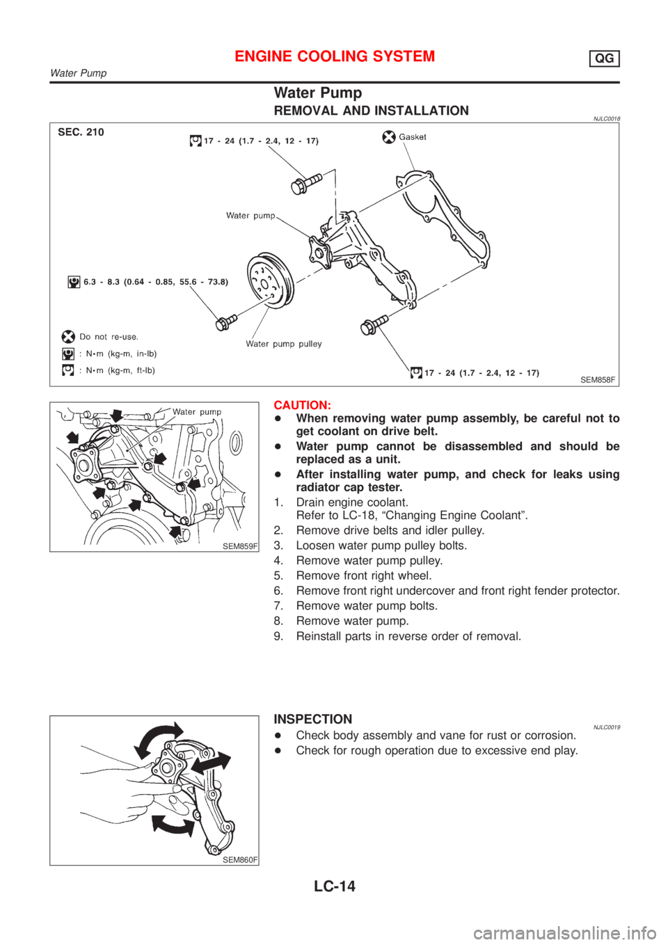
Water Pump
REMOVAL AND INSTALLATIONNJLC0018
SEM858F
SEM859F
CAUTION:
+When removing water pump assembly, be careful not to
get coolant on drive belt.
+Water pump cannot be disassembled and should be
replaced as a unit.
+After installing water pump, and check for leaks using
radiator cap tester.
1. Drain engine coolant.
Refer to LC-18, ªChanging Engine Coolantº.
2. Remove drive belts and idler pulley.
3. Loosen water pump pulley bolts.
4. Remove water pump pulley.
5. Remove front right wheel.
6. Remove front right undercover and front right fender protector.
7. Remove water pump bolts.
8. Remove water pump.
9. Reinstall parts in reverse order of removal.
SEM860F
INSPECTIONNJLC0019+Check body assembly and vane for rust or corrosion.
+Check for rough operation due to excessive end play.
ENGINE COOLING SYSTEMQG
Water Pump
LC-14
Page 2530 of 2898
SLC934
2. Check for leakage.
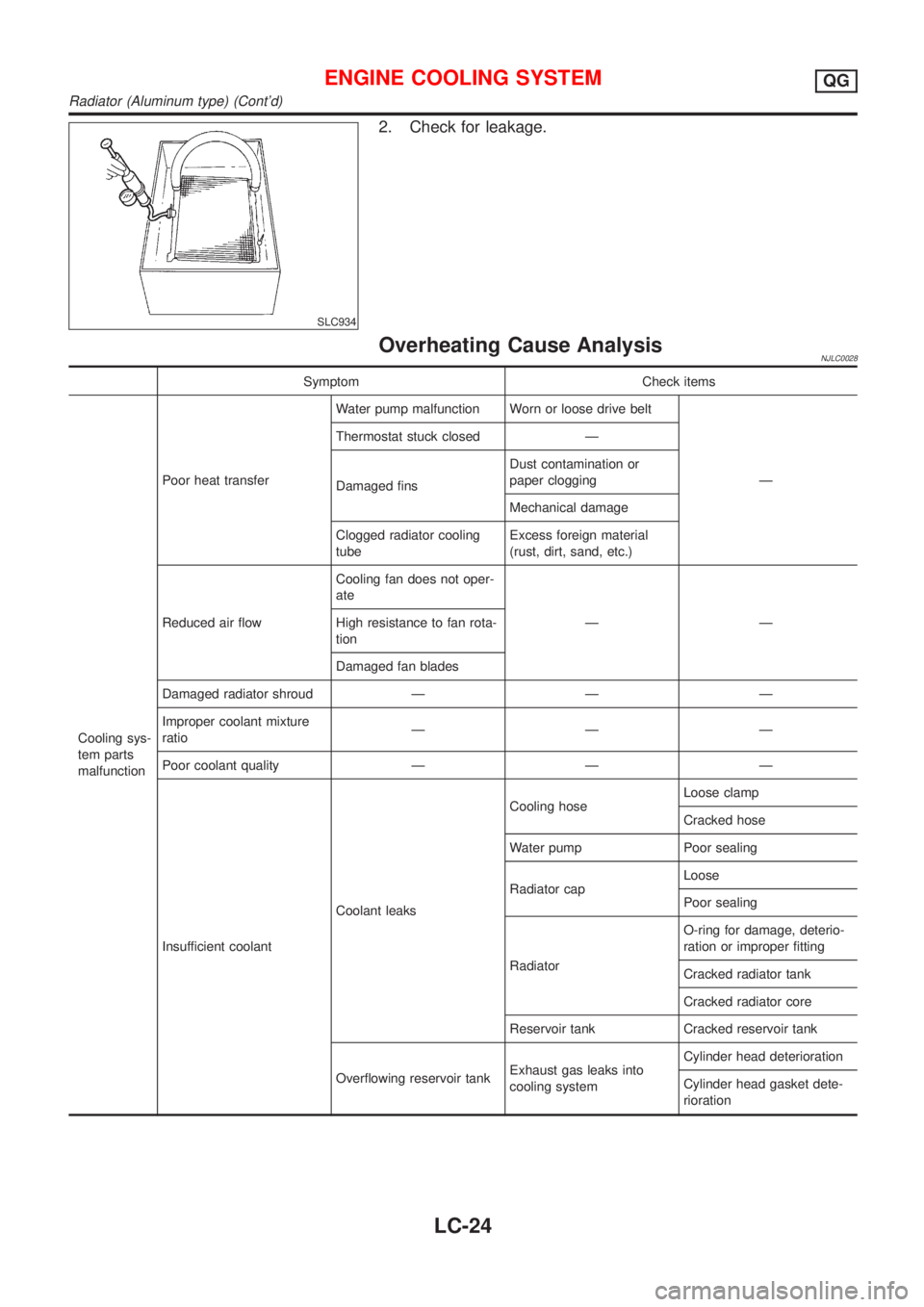
Overheating Cause AnalysisNJLC0028
Symptom Check items
Cooling sys-
tem parts
malfunctionPoor heat transferWater pump malfunction Worn or loose drive belt
Ð Thermostat stuck closed Ð
Damaged finsDust contamination or
paper clogging
Mechanical damage
Clogged radiator cooling
tubeExcess foreign material
(rust, dirt, sand, etc.)
Reduced air flowCooling fan does not oper-
ate
ÐÐ High resistance to fan rota-
tion
Damaged fan blades
Damaged radiator shroud Ð Ð Ð
Improper coolant mixture
ratioÐÐÐ
Poor coolant quality Ð Ð Ð
Insufficient coolantCoolant leaksCooling hoseLoose clamp
Cracked hose
Water pump Poor sealing
Radiator capLoose
Poor sealing
RadiatorO-ring for damage, deterio-
ration or improper fitting
Cracked radiator tank
Cracked radiator core
Reservoir tank Cracked reservoir tank
Overflowing reservoir tankExhaust gas leaks into
cooling systemCylinder head deterioration
Cylinder head gasket dete-
rioration
ENGINE COOLING SYSTEMQG
Radiator (Aluminum type) (Cont'd)
LC-24
Page 2545 of 2898
+Replace the radiator cap if abnormalities are found with the
negative pressure valve, or if the valve opening pressure is out
of the standard range.
SLC756AA
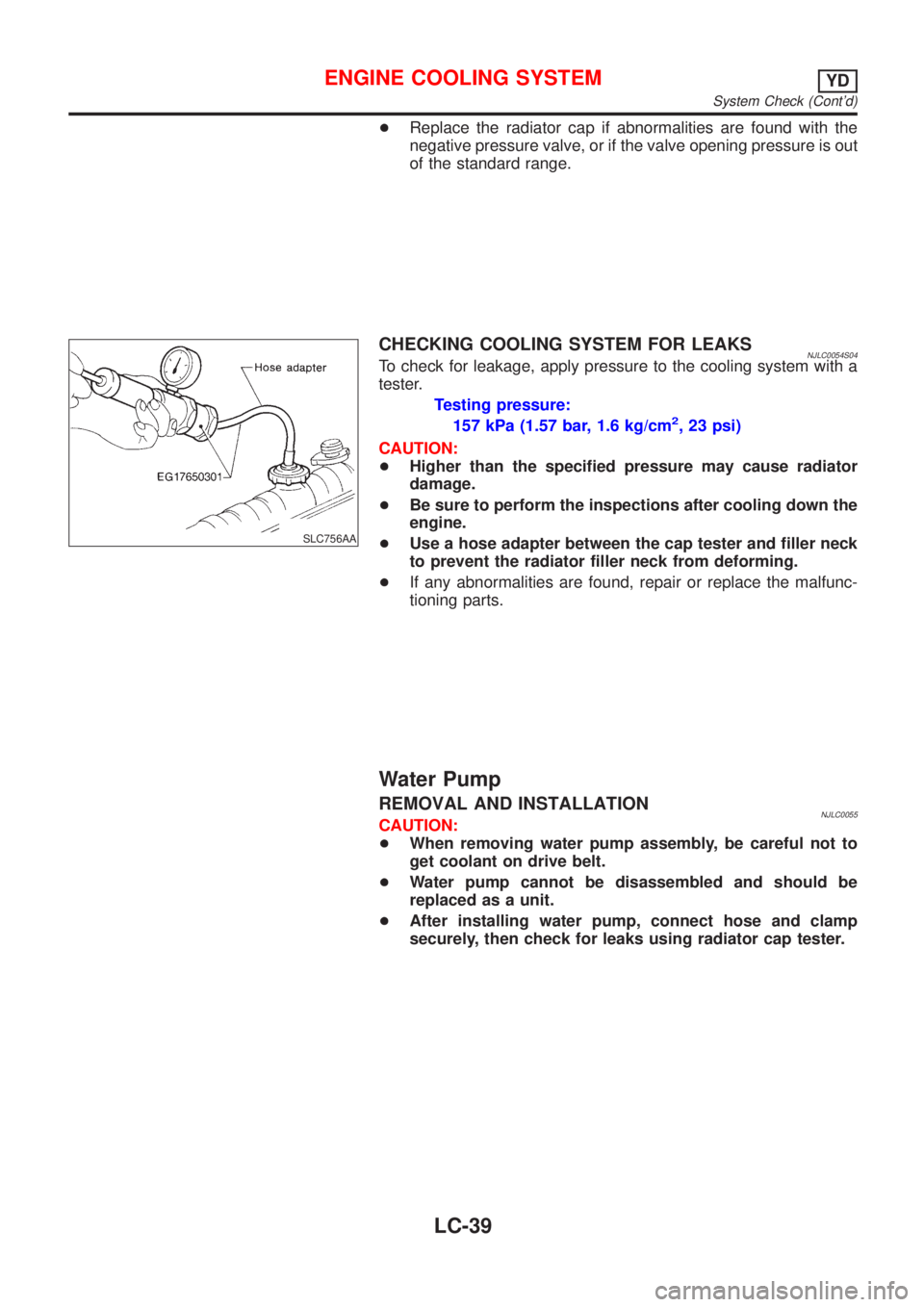
CHECKING COOLING SYSTEM FOR LEAKSNJLC0054S04To check for leakage, apply pressure to the cooling system with a
tester.
Testing pressure:
157 kPa (1.57 bar, 1.6 kg/cm
2, 23 psi)
CAUTION:
+Higher than the specified pressure may cause radiator
damage.
+Be sure to perform the inspections after cooling down the
engine.
+Use a hose adapter between the cap tester and filler neck
to prevent the radiator filler neck from deforming.
+If any abnormalities are found, repair or replace the malfunc-
tioning parts.
Water Pump
REMOVAL AND INSTALLATIONNJLC0055CAUTION:
+When removing water pump assembly, be careful not to
get coolant on drive belt.
+Water pump cannot be disassembled and should be
replaced as a unit.
+After installing water pump, connect hose and clamp
securely, then check for leaks using radiator cap tester.
ENGINE COOLING SYSTEMYD
System Check (Cont'd)
LC-39
Page 2546 of 2898
JLC294B
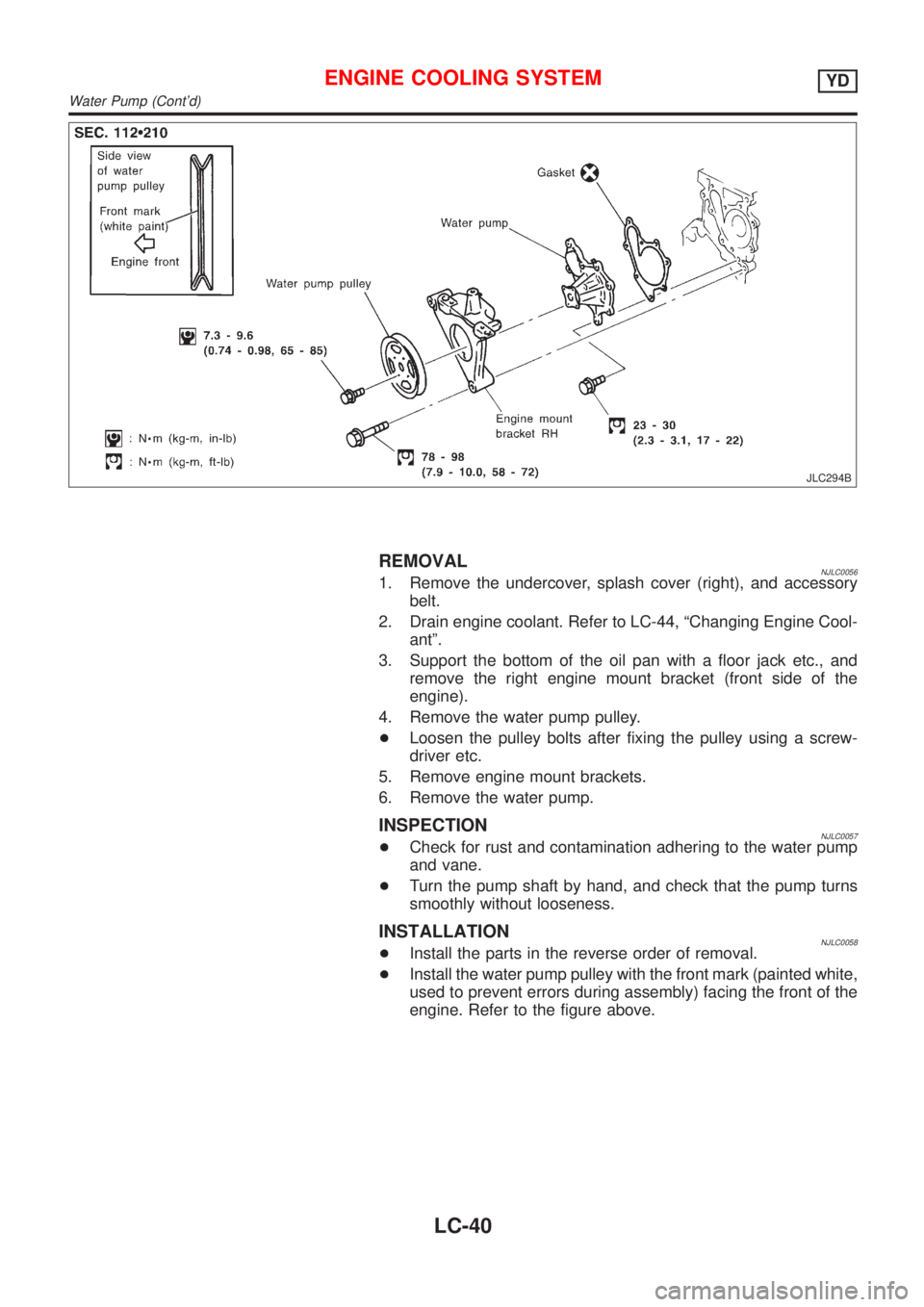
REMOVALNJLC00561. Remove the undercover, splash cover (right), and accessory
belt.
2. Drain engine coolant. Refer to LC-44, ªChanging Engine Cool-
antº.
3. Support the bottom of the oil pan with a floor jack etc., and
remove the right engine mount bracket (front side of the
engine).
4. Remove the water pump pulley.
+Loosen the pulley bolts after fixing the pulley using a screw-
driver etc.
5. Remove engine mount brackets.
6. Remove the water pump.
INSPECTIONNJLC0057+Check for rust and contamination adhering to the water pump
and vane.
+Turn the pump shaft by hand, and check that the pump turns
smoothly without looseness.
INSTALLATIONNJLC0058+Install the parts in the reverse order of removal.
+Install the water pump pulley with the front mark (painted white,
used to prevent errors during assembly) facing the front of the
engine. Refer to the figure above.
ENGINE COOLING SYSTEMYD
Water Pump (Cont'd)
LC-40